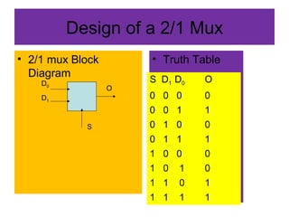
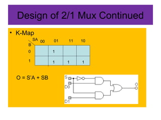
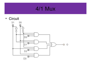
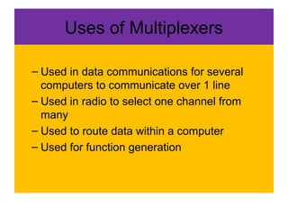
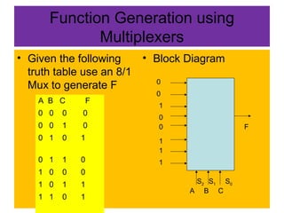
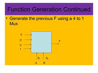
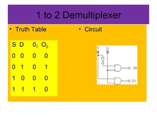
Representation of a
Dultiplexer and Demultiplexer
Explaining Their Types
Design of a 2/1 Mux
• 2/1 mux Block
Diagram
• Truth Table
D1
D0
S
O
S D1 D0 O
0 0 0 0
0 0 1 1
0 1 0 0
0 1 1 1
1 0 0 0
1 0 1 0
1 1 0 1
1 1 1 1
Design of 2/1 Mux Continued
• K-Map
SA
B
00 1101 10
0
1
1
1 1 1
O = S’A + SB
4/1 Mux
• Circuit
Uses of Multiplexers
– Used in data communications for several
computers to communicate over 1 line
– Used in radio to select one channel from
many
– Used to route data within a computer
– Used for function generation
Function Generation using
Multiplexers
• Given the following
truth table use an 8/1
Mux to generate F
• Block Diagram
A B C F
0 0 0 0
0 0 1 0
0 1 0 1
0 1 1 0
1 0 0 0
1 0 1 1
1 1 0 1
0
0
0
0
1
1
1
1
A B C
S2 S0S1
F
Function Generation Continued
• Generate the previous F using a 4 to 1
Mux
0
C’
C
1
A B
F
S1 S0
1 to 2 Demultiplexer
• Truth Table • Circuit
S D 01 O0
0 0 0 0
0 1 0 1
1 0 0 0
1 1 1 0

Multiplexers and demultiplexers 2

  • 1.
    Representation of a Dultiplexerand Demultiplexer Explaining Their Types
  • 2.
    Design of a2/1 Mux • 2/1 mux Block Diagram • Truth Table D1 D0 S O S D1 D0 O 0 0 0 0 0 0 1 1 0 1 0 0 0 1 1 1 1 0 0 0 1 0 1 0 1 1 0 1 1 1 1 1
  • 3.
    Design of 2/1Mux Continued • K-Map SA B 00 1101 10 0 1 1 1 1 1 O = S’A + SB
  • 4.
  • 5.
    Uses of Multiplexers –Used in data communications for several computers to communicate over 1 line – Used in radio to select one channel from many – Used to route data within a computer – Used for function generation
  • 6.
    Function Generation using Multiplexers •Given the following truth table use an 8/1 Mux to generate F • Block Diagram A B C F 0 0 0 0 0 0 1 0 0 1 0 1 0 1 1 0 1 0 0 0 1 0 1 1 1 1 0 1 0 0 0 0 1 1 1 1 A B C S2 S0S1 F
  • 7.
    Function Generation Continued •Generate the previous F using a 4 to 1 Mux 0 C’ C 1 A B F S1 S0
  • 8.
    1 to 2Demultiplexer • Truth Table • Circuit S D 01 O0 0 0 0 0 0 1 0 1 1 0 0 0 1 1 1 0