Download as PDF, PPTX

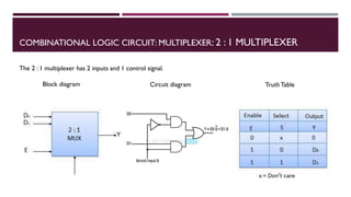
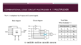
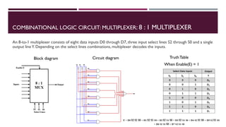
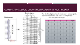


The document covers the fundamentals of digital electronics, specifically focusing on multiplexers, demultiplexers, encoders, decoders, and arithmetic logic units (ALUs). It describes the functions and configurations of different types of multiplexers and demultiplexers along with their applications in communication systems and ALUs. The document also outlines the logical operations and design considerations associated with these digital components.