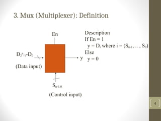
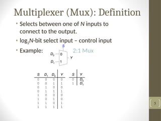
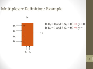
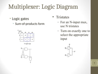
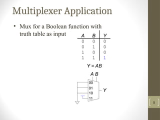
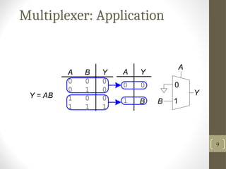
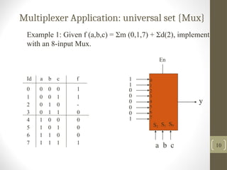
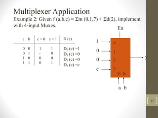
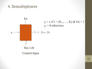
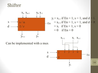
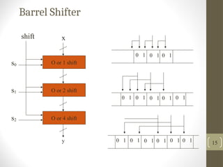
Combinational Circuits
1
2
Part III. Standard Modules
Interconnect Modules:
1. Decoder, 2. Encoder
3. Multiplexer, 4. Demultiplexer
Multiplexer
• Definition
• Logic Diagram
• Application
3
3. Mux (Multiplexer): Definition
4
Description
If En = 1
y = Di where i = (Sn-1, .. , S0)
Else
y = 0
En
y
D2
n
-1-D0
(Data input)
Sn-1,0
(Control input)
Multiplexer (Mux): Definition
• Selects between one of N inputs to
connect to the output.
• log2N-bit select input – control input
• Example: 2:1 Mux
Y
0 0
0 1
1 0
1 1
0
1
0
1
0
0
0
0
0 0
0 1
1 0
1 1
1
1
1
1
0
0
1
1
0
1
S
D0
Y
D1
D1 D0
S Y
0
1 D1
D0
S
5
6
Multiplexer Definition: Example
En
y
S1 S0
D0
D1
D2
D3
0
1
2
3
If D0 = 0 and S1S0 = 00 => y = 0
If D0 = 1 and S1S0 = 00 => y = 1
Multiplexer: Logic Diagram
• Logic gates
• Sum-of-products form
Y
D0
S
D1
D1
Y
D0
S
S
00 01
0
1
Y
1
1 10
D0 D1
0
0
0
1
1
1
1
0
Y=D0S +D1S
7
• Tristates
– For an N-input mux,
use N tristates
– Turn on exactly one to
select the appropriate
input
Multiplexer Application
A B Y
0 0 0
0 1 0
1 0 0
1 1 1
Y = AB
00
Y
01
10
11
A B
8
• Mux for a Boolean function with
truth table as input
Multiplexer: Application
A B Y
0 0 0
0 1 0
1 0 0
1 1 1
Y = AB
A Y
0
1
0 0
1
A
B
Y
B
9
Multiplexer Application: universal set {Mux}
10
Example 1: Given f (a,b,c) = m (0,1,7) + d(2), implement
with an 8-input Mux.
Id a b c f
0 0 0 0 1
1 0 0 1 1
2 0 1 0 -
3 0 1 1 0
4 1 0 0 0
5 1 0 1 0
6 1 1 0 0
7 1 1 1 1
En
y
1
1
0
0
0
0
0
1
a b c
S2 S1 S0
0
1
2
3
4
5
6
7
a
0
0
1
1
b
0
1
0
1
c = 0
1
-
0
0
c = 1
1
0
0
1
D (c)
D0 (c) =1
D1 (c) =0
D2 (c) =0
D3 (c) =c
En
y
1
0
c
a b
S1 S0
0
0
1
2
3
Multiplexer Application
Example 2: Given f (a,b,c) = m (0,1,7) + d(2), implement
with 4-input Muxes.
11
a
0
1
00 01 10 11
1 1 - 0
0 0 0 1
D (b,c)
D0 (b,c)
D1 (b,c)
D1 (b,c)
b
0
1
c = 0
0
0
c = 1
0
1
l1(0) = 0
l1(c) = c
En
En b’ 0
1
a
b
y
0
1
0
c
D0 (b,c) = b’ D1 (b,c) = bc
1 -
1 0
c
b
0 0
0 1
c
b
Multiplexer Application
Example 3: Given f (a,b,c) = m (0,1,7) + d(2), implement
with 2-input Muxes.
12
4. Demultiplexers
13
En
x y2n-1 -y0
S(n-1,0)
Control Input
yi = x if i = (Sn-1, .. , S0) & En = 1
yi = 0 otherwise
Shifter
14
Can be implemented with a mux
s
d
yi
En
1
0
3 2 1 0
xi+1 xi-1
xi
s
d
xn x0 x-1
xn-1
yn-1 y0
En
s / n
l / r
yi = xi-1 if En = 1, s = 1, and d = L
= xi+1 if En = 1, s = 1, and d = R
= xi if En = 1, s = 0
= 0 if En = 0
Barrel Shifter
15
O or 1 shift
O or 2 shift
O or 4 shift
x
s0
s1
s2
y
0 1 0 1 0 1
0 1 0 1 0 1
0 1 0 1
0 1 0 1 0 1
0 1 0 1 0 1
shift

combinational circuits - Multiplexer and Demultiplexer

  • 1.
  • 2.
    2 Part III. StandardModules Interconnect Modules: 1. Decoder, 2. Encoder 3. Multiplexer, 4. Demultiplexer
  • 3.
    Multiplexer • Definition • LogicDiagram • Application 3
  • 4.
    3. Mux (Multiplexer):Definition 4 Description If En = 1 y = Di where i = (Sn-1, .. , S0) Else y = 0 En y D2 n -1-D0 (Data input) Sn-1,0 (Control input)
  • 5.
    Multiplexer (Mux): Definition •Selects between one of N inputs to connect to the output. • log2N-bit select input – control input • Example: 2:1 Mux Y 0 0 0 1 1 0 1 1 0 1 0 1 0 0 0 0 0 0 0 1 1 0 1 1 1 1 1 1 0 0 1 1 0 1 S D0 Y D1 D1 D0 S Y 0 1 D1 D0 S 5
  • 6.
    6 Multiplexer Definition: Example En y S1S0 D0 D1 D2 D3 0 1 2 3 If D0 = 0 and S1S0 = 00 => y = 0 If D0 = 1 and S1S0 = 00 => y = 1
  • 7.
    Multiplexer: Logic Diagram •Logic gates • Sum-of-products form Y D0 S D1 D1 Y D0 S S 00 01 0 1 Y 1 1 10 D0 D1 0 0 0 1 1 1 1 0 Y=D0S +D1S 7 • Tristates – For an N-input mux, use N tristates – Turn on exactly one to select the appropriate input
  • 8.
    Multiplexer Application A BY 0 0 0 0 1 0 1 0 0 1 1 1 Y = AB 00 Y 01 10 11 A B 8 • Mux for a Boolean function with truth table as input
  • 9.
    Multiplexer: Application A BY 0 0 0 0 1 0 1 0 0 1 1 1 Y = AB A Y 0 1 0 0 1 A B Y B 9
  • 10.
    Multiplexer Application: universalset {Mux} 10 Example 1: Given f (a,b,c) = m (0,1,7) + d(2), implement with an 8-input Mux. Id a b c f 0 0 0 0 1 1 0 0 1 1 2 0 1 0 - 3 0 1 1 0 4 1 0 0 0 5 1 0 1 0 6 1 1 0 0 7 1 1 1 1 En y 1 1 0 0 0 0 0 1 a b c S2 S1 S0 0 1 2 3 4 5 6 7
  • 11.
    a 0 0 1 1 b 0 1 0 1 c = 0 1 - 0 0 c= 1 1 0 0 1 D (c) D0 (c) =1 D1 (c) =0 D2 (c) =0 D3 (c) =c En y 1 0 c a b S1 S0 0 0 1 2 3 Multiplexer Application Example 2: Given f (a,b,c) = m (0,1,7) + d(2), implement with 4-input Muxes. 11
  • 12.
    a 0 1 00 01 1011 1 1 - 0 0 0 0 1 D (b,c) D0 (b,c) D1 (b,c) D1 (b,c) b 0 1 c = 0 0 0 c = 1 0 1 l1(0) = 0 l1(c) = c En En b’ 0 1 a b y 0 1 0 c D0 (b,c) = b’ D1 (b,c) = bc 1 - 1 0 c b 0 0 0 1 c b Multiplexer Application Example 3: Given f (a,b,c) = m (0,1,7) + d(2), implement with 2-input Muxes. 12
  • 13.
    4. Demultiplexers 13 En x y2n-1-y0 S(n-1,0) Control Input yi = x if i = (Sn-1, .. , S0) & En = 1 yi = 0 otherwise
  • 14.
    Shifter 14 Can be implementedwith a mux s d yi En 1 0 3 2 1 0 xi+1 xi-1 xi s d xn x0 x-1 xn-1 yn-1 y0 En s / n l / r yi = xi-1 if En = 1, s = 1, and d = L = xi+1 if En = 1, s = 1, and d = R = xi if En = 1, s = 0 = 0 if En = 0
  • 15.
    Barrel Shifter 15 O or1 shift O or 2 shift O or 4 shift x s0 s1 s2 y 0 1 0 1 0 1 0 1 0 1 0 1 0 1 0 1 0 1 0 1 0 1 0 1 0 1 0 1 shift