Downloaded 469 times

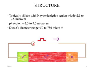


The TRAPATT diode is a microwave semiconductor device that operates as both an amplifier and oscillator below 10 GHz. It consists of an N-type semiconductor with a depletion region width of 2.5-12.5 micrometers and a P+ region of 2.5-7.5 micrometers in diameter. When a high voltage is applied, an avalanche zone propagates through the diode, trapping electrons and holes in the depletion region and allowing the diode to efficiently deliver RF power to an external load. The TRAPATT diode has advantages of high efficiency between 15-40% and low power dissipation, making it suitable for pulsed applications like low power Doppler radars between 3-50 GHz.