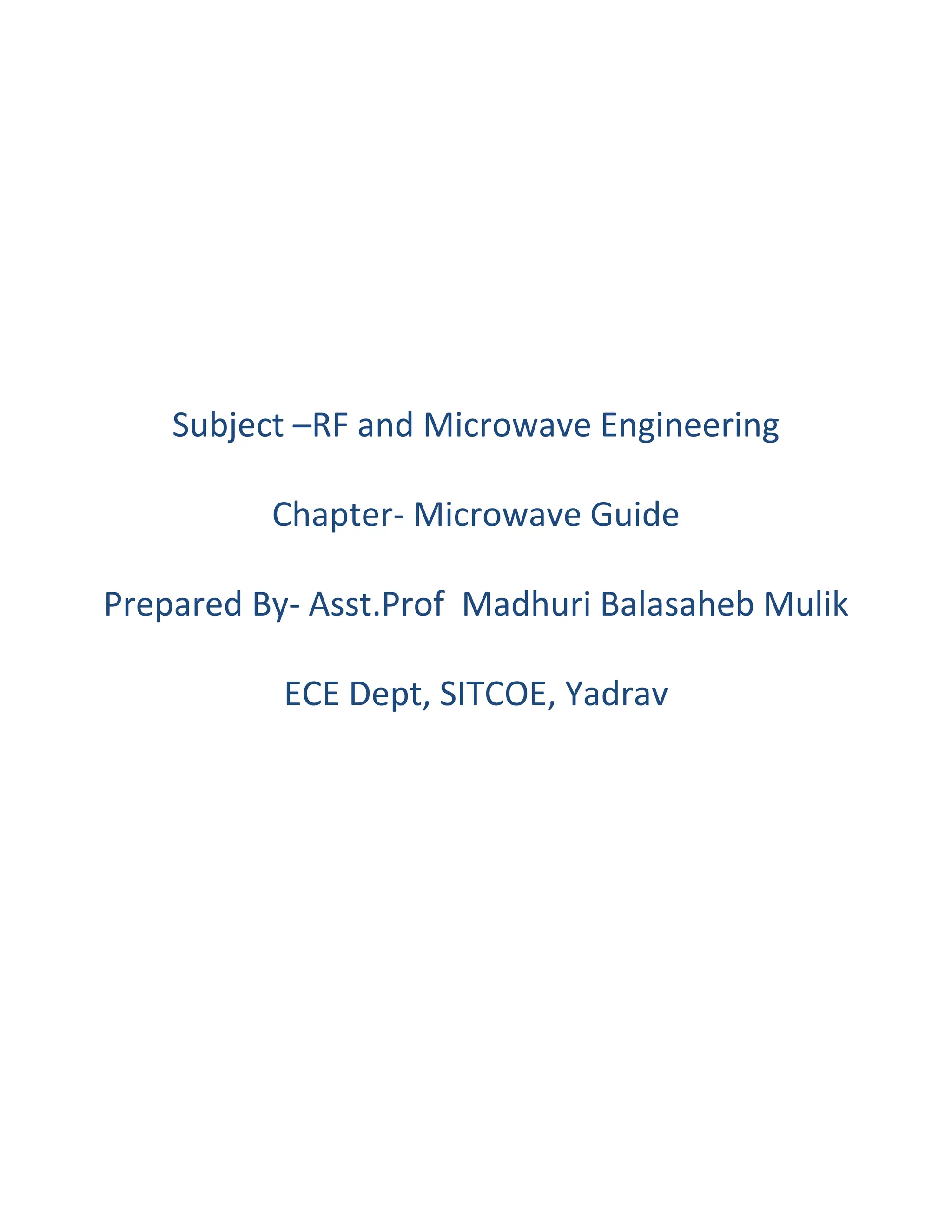
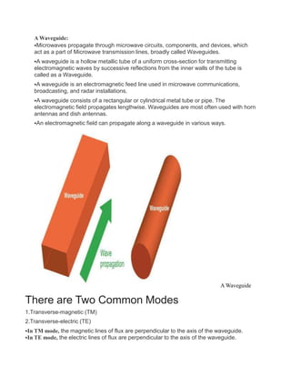
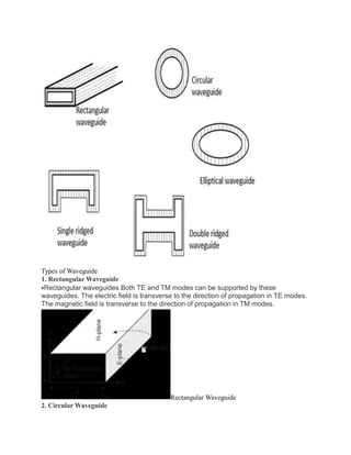
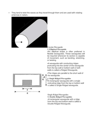
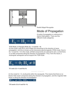
Subject –RF and Microwave Engineering
Chapter- Microwave Guide
Prepared By- Asst.Prof Madhuri Balasaheb Mulik
ECE Dept, SITCOE, Yadrav
A Waveguide:
Microwaves propagate through microwave circuits, components, and devices, which
act as a part of Microwave transmission lines, broadly called Waveguides.
A waveguide is a hollow metallic tube of a uniform cross-section for transmitting
electromagnetic waves by successive reflections from the inner walls of the tube is
called as a Waveguide.
A waveguide is an electromagnetic feed line used in microwave communications,
broadcasting, and radar installations.
A waveguide consists of a rectangular or cylindrical metal tube or pipe. The
electromagnetic field propagates lengthwise. Waveguides are most often used with horn
antennas and dish antennas.
An electromagnetic field can propagate along a waveguide in various ways.
A Waveguide
There are Two Common Modes
1.Transverse-magnetic (TM)
2.Transverse-electric (TE)
In TM mode, the magnetic lines of flux are perpendicular to the axis of the waveguide.
In TE mode, the electric lines of flux are perpendicular to the axis of the waveguide.
 A waveguide must have a certain minimum diameter relative to the wavelength of the
signal, to work for the waveguide to work properly.
 If the waveguide is too narrow or the frequency is too low (the wavelength is too long),
the electromagnetic fields cannot propagate.
Characteristics of Waveguide
 The tube wall provides distributed inductance.
 The space between the tube walls provides distributed capacitance.
 These are bulky, heavy, and expensive.
Types of Waveguide
There are five types of waveguides.
Types of Waveguide
1. Rectangular Waveguide
Rectangular waveguides Both TE and TM modes can be supported by these
waveguides. The electric field is transverse to the direction of propagation in TE modes.
The magnetic field is transverse to the direction of propagation in TM modes.
Rectangular Waveguide
2. Circular Waveguide
 They tend to twist the waves as they travel through them and are used with rotating
antennas in radars.
Circular Waveguide
3. Elliptical Waveguide
An elliptical shape is often preferred in
flexible waveguides. These waveguides will
be required whenever its section is capable
of movement, such as bending, stretching,
or twisting.
A waveguide with conducting ridges
protruding into the center of the waveguide
from the top wall or bottom wall or both
walls is called a Ridged Waveguide.
The ridges are parallel to the short wall of
the waveguide.
4. Single Ridged Waveguides
A rectangular waveguide with a single
protruding ridge from the top or bottom wall
is called a Single Ridged waveguide.
Single Ridged Waveguides
5. Double Ridged Waveguides
A rectangular waveguide with a ridge
from the top and bottom wall is called a
Double Ridged Waveguide.
Double Ridged Waveguides
Mode of Propagation
A mode of propagation is nothing but a
distinct field pattern. There are four
different mode categories.
TEM Mode or Principal Mode (Ez = 0 and Hz = 0)
In this mode, both the E and H fields are transverse to the direction of wave
propagation, and this is known as the transverse electromagnetic (TEM) mode. Due to
Ez = 0 and Hz = 0 in this mode, all field components are reduced to zero, so that there
is no field component along the direction of propagation. Thus, from the result, a
rectangular waveguide cannot support the TEM mode.
TE mode (Ez= 0 and Hz≠ 0)
A D V E R T I S E M E N T
In this mode Ez = 0, at all points within the waveguide. This means that there is no
electric field vector component along the direction of propagation, and the magnetic field
vector is along the direction of propagation.
TM modes (Ez≠ 0 and Hz= 0)
 In this mode Hz = 0 at all points within the waveguide. This means that there is no
magnetic field vector component along the direction of propagation, and the electric field
vector is parallel to the long axis.
HE modes (Ez≠ 0 and Hz= 0)
In this case, neither E nor H field is transverse to the direction of wave propagation,
and they are known as hybrid modes.
Parameters of a Waveguide
Cut-off wavelength
It is the maximum signal wavelength of the transmitted signal that can be propagated
within the waveguide without any attenuation. It is denoted by λc.
Group velocity
Group velocity is the velocity with which the wave propagates inside the waveguide.
If the transmitted carrier is modulated, then the velocity of the modulation envelope is
somewhat less as compared to the carrier signal.
This velocity of the envelope is termed group velocity. It is represented by Vg.
Phase velocity
It is the velocity with which the transmitted wave changes its phase during propagation.
It is the velocity of a particular phase of the propagating wave. It is denoted by Vp.
Wave Impedance
It is also known as the characteristic impedance.
It is defined as the ratio of the transverse electric field to that of the transverse
magnetic field during wave propagation at any point inside the waveguide.
It is denoted by Zg.
Circular Cavity Resonators
Circular Cavity Resonator
A circular cavity resonator is a circular waveguide
with two ends closed by a metallic wall. The field
components inside the cavity are described as TEnmp
and TMnmp
TE Mode:
It is described by the equation,
Hz = Ho Jn (x’nmp ρ/a) cos nΦ sin(pπz/d)
Where a, ρ and Φ are the cylindrical coordinates
TM Mode:
It is defined by the Equation,
Ez = Eo Jn (x’nmp ρ/a) cos nΦ sin(pπz/d)
For the rectangular cavity resonator, the resonant frequency is given by fr
= 1/2√(μƐ) √{(m/a)2 + (n/b)2 + (p/d)2}
for circular cavity resonator, the resonant frequency is given by fr =
1/2π√(μƐ) √{( xnmp /a)2 + (pπ/d)2}
Rectangular and circular cavity resonators
Resonator is a tuned circuit which resonates at a particular frequency at
which the energy stored in the electric field is equal to the energy stored in the
magnetic field.
Resonant frequency of microwave resonator is the frequency at which the energy
in the resonator attains maximum value. i.e., twice the electric energy or
magnetic energy.
At low frequencies upto VHF (300 MHz), the resonator is made up of the reactive
elements or the lumped elements like the capacitance and the
inductance.
The inductance and the capacitance values are too small as the frequency is
increased beyond the VHF range and hence difficult to realize.
Transmission line resonator can be built using distributed elements like
sections of coaxial lines. The coaxial lines are either opened or shunted at the
end sections thus confining the electromagnetic energy within the section and
acts as the resonant circuit having a natural resonant frequency.
At very high frequencies transmission line resonator does not give very high
quality factor Q due to skin effect and radiation loss. So, transmission line
resonator is not used as microwave resonator.
The performance parameters of microwave resonator are:
(i) Resonant frequency (ii)Quality factor
(iii) Input impedance Quality Factor of a Resonator.:
•The quality factor Q is a measure of frequency selectivity of the resonator.
•It is defined as Q = 2 x Maximum energy stored / Energy dissipated per cycle = W
/ P
Where,
a. W is the maximum stored energy
b. P is the average power loss
The methods used for constructing a resonator:
The resonators are built by,
a)Using lumped elements like L and C
b)Using distributed elements like sections of coaxial lines
c)Using rectangular or circular waveguide There are two types of cavity
resonators.
a)Rectangular cavity resonator b)Circular cavity resonator
Rectangular or circular cavities can be used as microwave resonators
because they have natural resonant frequency and behave like a LCR circuit.
Cavity resonator can be represented by a LCR circuit as:
•The electromagnetic energy is stored in the entire volume of the cavity in the
form of electric and magnetic fields.
•The presence of electric field gives rise to a capacitance value and the
presence of magnetic field gives rise to a inductance value and the finite
conductivity in the walls gives rise to loss along the walls giving rise to a
resistance value.
• Thus the cavity resonator can be represented by a equivalent LCR circuit
and have a natural resonant frequency.
* Cavity resonators are formed by placing the perfectly conducting sheets on
the rectangular or circular waveguide on the two end sections and hence all the
sides are surrounded by the conducting walls thus forming a cavity.
* The electromagnetic energy is confined within this metallic enclosure and
they acts as resonant circuits.
Note:TE101 mode is the dominant mode of the rectangular resonator in case
of a>b<d.
Circular Cavity Resonators:
For an air-filled circular cylindrical cavity resonator of radius a and length d. The
resonant frequencies are,
In case of 2d>2a>d, the dominant mode of the circular cylindrical cavity is TM010
mode:

CPT1-Waveguide.ppt

  • 1.
    Subject –RF andMicrowave Engineering Chapter- Microwave Guide Prepared By- Asst.Prof Madhuri Balasaheb Mulik ECE Dept, SITCOE, Yadrav
  • 2.
    A Waveguide: Microwaves propagatethrough microwave circuits, components, and devices, which act as a part of Microwave transmission lines, broadly called Waveguides. A waveguide is a hollow metallic tube of a uniform cross-section for transmitting electromagnetic waves by successive reflections from the inner walls of the tube is called as a Waveguide. A waveguide is an electromagnetic feed line used in microwave communications, broadcasting, and radar installations. A waveguide consists of a rectangular or cylindrical metal tube or pipe. The electromagnetic field propagates lengthwise. Waveguides are most often used with horn antennas and dish antennas. An electromagnetic field can propagate along a waveguide in various ways. A Waveguide There are Two Common Modes 1.Transverse-magnetic (TM) 2.Transverse-electric (TE) In TM mode, the magnetic lines of flux are perpendicular to the axis of the waveguide. In TE mode, the electric lines of flux are perpendicular to the axis of the waveguide.
  • 3.
     A waveguidemust have a certain minimum diameter relative to the wavelength of the signal, to work for the waveguide to work properly.  If the waveguide is too narrow or the frequency is too low (the wavelength is too long), the electromagnetic fields cannot propagate. Characteristics of Waveguide  The tube wall provides distributed inductance.  The space between the tube walls provides distributed capacitance.  These are bulky, heavy, and expensive. Types of Waveguide There are five types of waveguides.
  • 4.
    Types of Waveguide 1.Rectangular Waveguide Rectangular waveguides Both TE and TM modes can be supported by these waveguides. The electric field is transverse to the direction of propagation in TE modes. The magnetic field is transverse to the direction of propagation in TM modes. Rectangular Waveguide 2. Circular Waveguide
  • 5.
     They tendto twist the waves as they travel through them and are used with rotating antennas in radars. Circular Waveguide 3. Elliptical Waveguide An elliptical shape is often preferred in flexible waveguides. These waveguides will be required whenever its section is capable of movement, such as bending, stretching, or twisting. A waveguide with conducting ridges protruding into the center of the waveguide from the top wall or bottom wall or both walls is called a Ridged Waveguide. The ridges are parallel to the short wall of the waveguide. 4. Single Ridged Waveguides A rectangular waveguide with a single protruding ridge from the top or bottom wall is called a Single Ridged waveguide. Single Ridged Waveguides 5. Double Ridged Waveguides A rectangular waveguide with a ridge from the top and bottom wall is called a Double Ridged Waveguide.
  • 6.
    Double Ridged Waveguides Modeof Propagation A mode of propagation is nothing but a distinct field pattern. There are four different mode categories. TEM Mode or Principal Mode (Ez = 0 and Hz = 0) In this mode, both the E and H fields are transverse to the direction of wave propagation, and this is known as the transverse electromagnetic (TEM) mode. Due to Ez = 0 and Hz = 0 in this mode, all field components are reduced to zero, so that there is no field component along the direction of propagation. Thus, from the result, a rectangular waveguide cannot support the TEM mode. TE mode (Ez= 0 and Hz≠ 0) A D V E R T I S E M E N T In this mode Ez = 0, at all points within the waveguide. This means that there is no electric field vector component along the direction of propagation, and the magnetic field vector is along the direction of propagation. TM modes (Ez≠ 0 and Hz= 0)
  • 7.
     In thismode Hz = 0 at all points within the waveguide. This means that there is no magnetic field vector component along the direction of propagation, and the electric field vector is parallel to the long axis. HE modes (Ez≠ 0 and Hz= 0) In this case, neither E nor H field is transverse to the direction of wave propagation, and they are known as hybrid modes. Parameters of a Waveguide Cut-off wavelength It is the maximum signal wavelength of the transmitted signal that can be propagated within the waveguide without any attenuation. It is denoted by λc. Group velocity Group velocity is the velocity with which the wave propagates inside the waveguide. If the transmitted carrier is modulated, then the velocity of the modulation envelope is somewhat less as compared to the carrier signal. This velocity of the envelope is termed group velocity. It is represented by Vg. Phase velocity It is the velocity with which the transmitted wave changes its phase during propagation. It is the velocity of a particular phase of the propagating wave. It is denoted by Vp. Wave Impedance It is also known as the characteristic impedance. It is defined as the ratio of the transverse electric field to that of the transverse magnetic field during wave propagation at any point inside the waveguide. It is denoted by Zg.
  • 8.
    Circular Cavity Resonators CircularCavity Resonator A circular cavity resonator is a circular waveguide with two ends closed by a metallic wall. The field components inside the cavity are described as TEnmp and TMnmp TE Mode: It is described by the equation, Hz = Ho Jn (x’nmp ρ/a) cos nΦ sin(pπz/d) Where a, ρ and Φ are the cylindrical coordinates TM Mode: It is defined by the Equation, Ez = Eo Jn (x’nmp ρ/a) cos nΦ sin(pπz/d) For the rectangular cavity resonator, the resonant frequency is given by fr = 1/2√(μƐ) √{(m/a)2 + (n/b)2 + (p/d)2} for circular cavity resonator, the resonant frequency is given by fr = 1/2π√(μƐ) √{( xnmp /a)2 + (pπ/d)2}
  • 9.
    Rectangular and circularcavity resonators Resonator is a tuned circuit which resonates at a particular frequency at which the energy stored in the electric field is equal to the energy stored in the magnetic field. Resonant frequency of microwave resonator is the frequency at which the energy in the resonator attains maximum value. i.e., twice the electric energy or magnetic energy. At low frequencies upto VHF (300 MHz), the resonator is made up of the reactive elements or the lumped elements like the capacitance and the inductance. The inductance and the capacitance values are too small as the frequency is increased beyond the VHF range and hence difficult to realize. Transmission line resonator can be built using distributed elements like sections of coaxial lines. The coaxial lines are either opened or shunted at the end sections thus confining the electromagnetic energy within the section and acts as the resonant circuit having a natural resonant frequency. At very high frequencies transmission line resonator does not give very high quality factor Q due to skin effect and radiation loss. So, transmission line resonator is not used as microwave resonator. The performance parameters of microwave resonator are: (i) Resonant frequency (ii)Quality factor (iii) Input impedance Quality Factor of a Resonator.:
  • 10.
    •The quality factorQ is a measure of frequency selectivity of the resonator. •It is defined as Q = 2 x Maximum energy stored / Energy dissipated per cycle = W / P Where, a. W is the maximum stored energy b. P is the average power loss The methods used for constructing a resonator: The resonators are built by, a)Using lumped elements like L and C b)Using distributed elements like sections of coaxial lines c)Using rectangular or circular waveguide There are two types of cavity resonators. a)Rectangular cavity resonator b)Circular cavity resonator Rectangular or circular cavities can be used as microwave resonators because they have natural resonant frequency and behave like a LCR circuit. Cavity resonator can be represented by a LCR circuit as: •The electromagnetic energy is stored in the entire volume of the cavity in the form of electric and magnetic fields. •The presence of electric field gives rise to a capacitance value and the presence of magnetic field gives rise to a inductance value and the finite conductivity in the walls gives rise to loss along the walls giving rise to a resistance value.
  • 11.
    • Thus thecavity resonator can be represented by a equivalent LCR circuit and have a natural resonant frequency. * Cavity resonators are formed by placing the perfectly conducting sheets on the rectangular or circular waveguide on the two end sections and hence all the sides are surrounded by the conducting walls thus forming a cavity. * The electromagnetic energy is confined within this metallic enclosure and they acts as resonant circuits.
  • 12.
    Note:TE101 mode isthe dominant mode of the rectangular resonator in case of a>b<d. Circular Cavity Resonators: For an air-filled circular cylindrical cavity resonator of radius a and length d. The resonant frequencies are,
  • 13.
    In case of2d>2a>d, the dominant mode of the circular cylindrical cavity is TM010 mode: