Downloaded 1,055 times


This document provides an overview of cathode ray oscilloscopes (CROs). It discusses the introduction and basic diagram of a CRO, describing the main components of the cathode ray tube. It also covers multi-input oscilloscopes, describing the alternate and chopped modes of dual trace oscilloscopes and methods for generating dual beams. Additionally, it discusses Lissajous patterns generated from two input signals and how they can be used to measure frequency and phase. Finally, it provides an overview of digital storage oscilloscopes, including their block diagram and advantages over analog storage oscilloscopes.
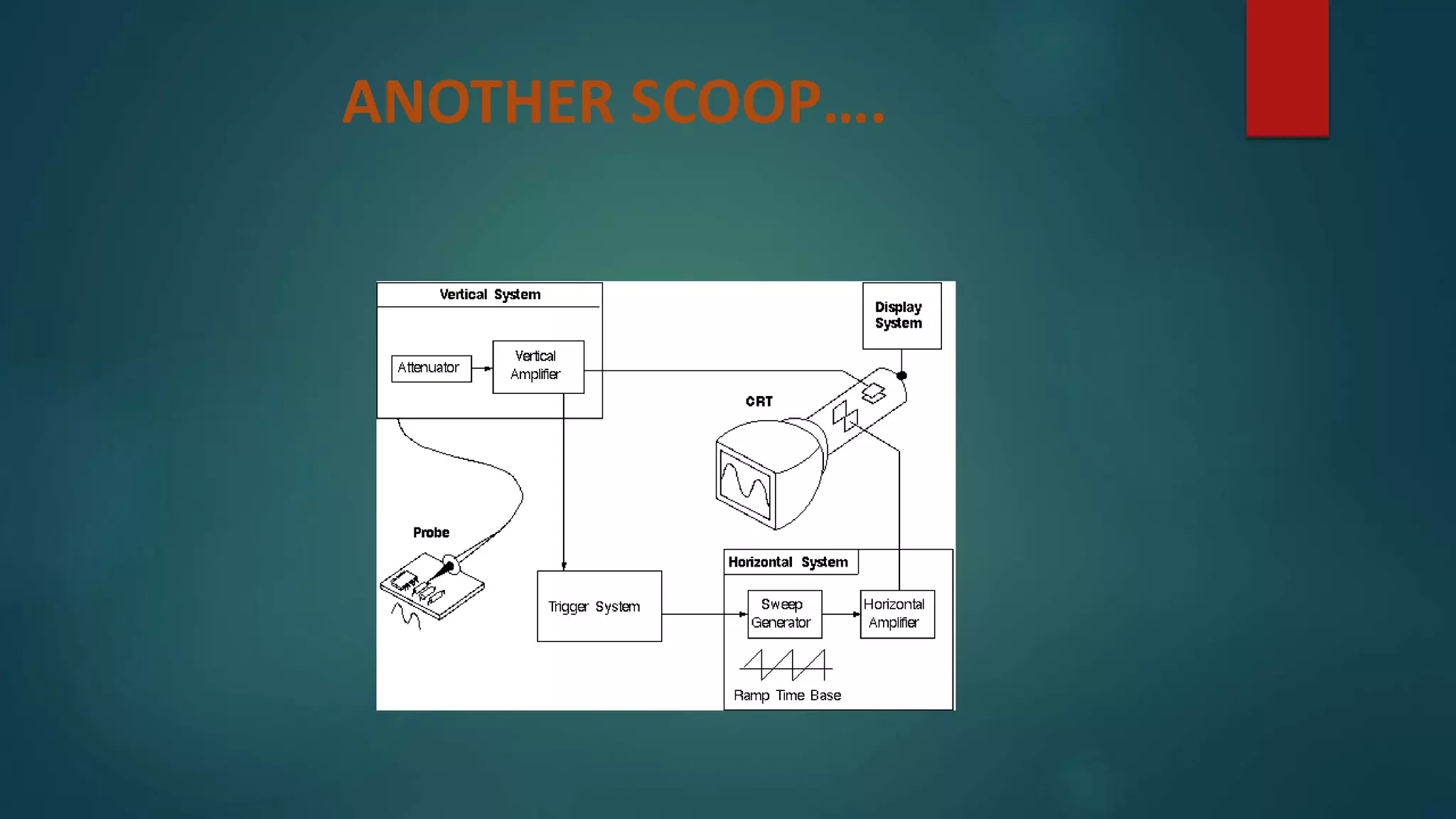
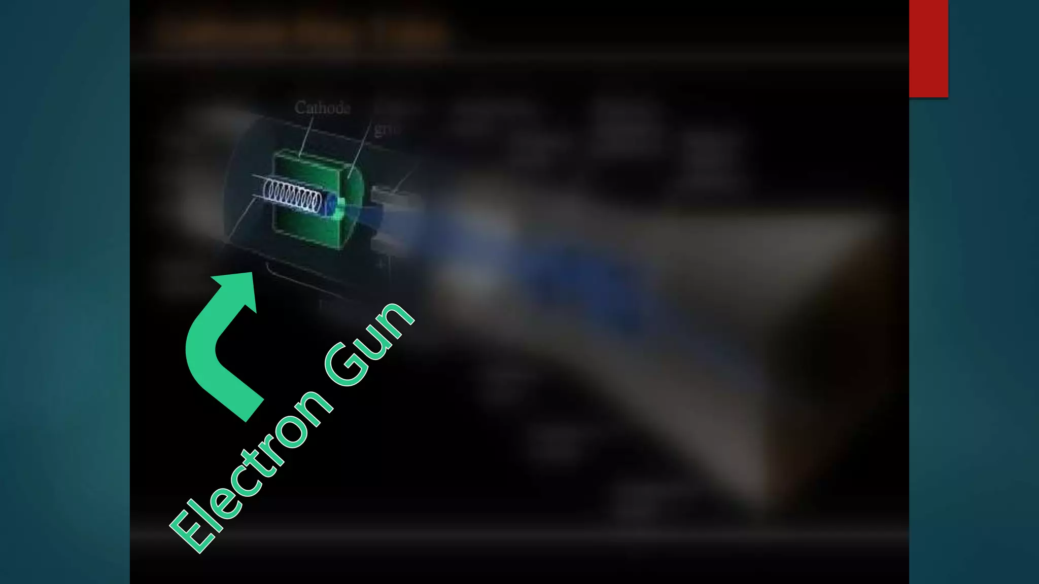
Introduction to Cathode Ray Oscilloscope (CRO) covering functions, visualization of signals, and basic diagrams.
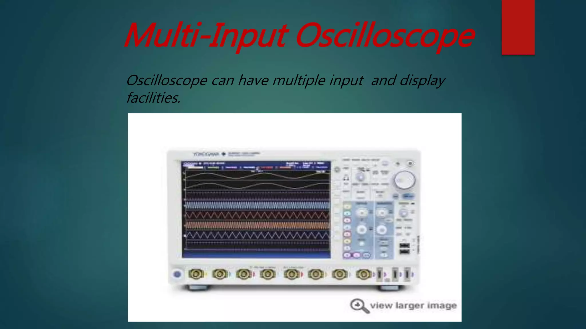
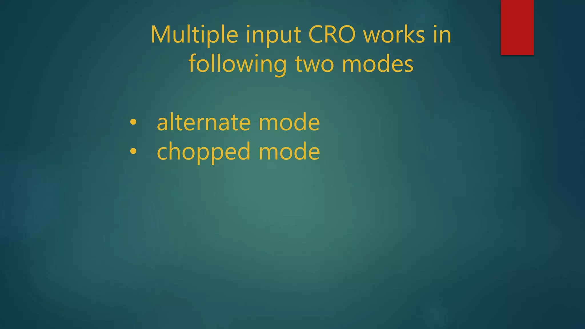
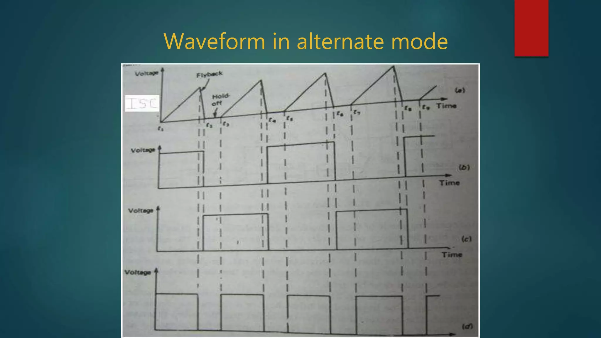
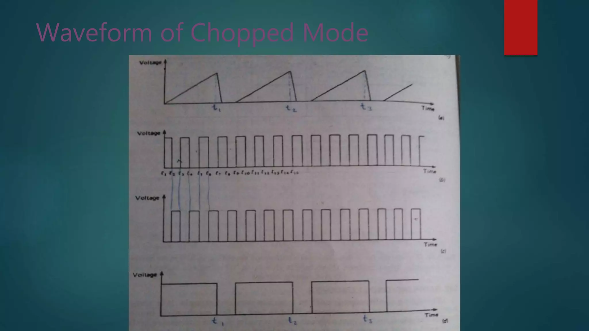
Details on multi-input oscilloscope capabilities, types including single and dual beam oscilloscopes, and modes of operation.
Lissajous patterns are used in CRO for frequency and phase measurements demonstrated with formulas.
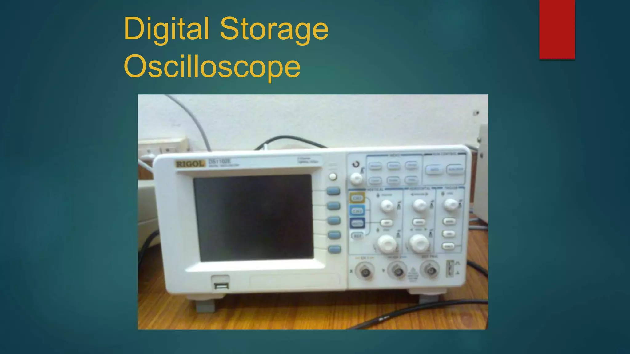
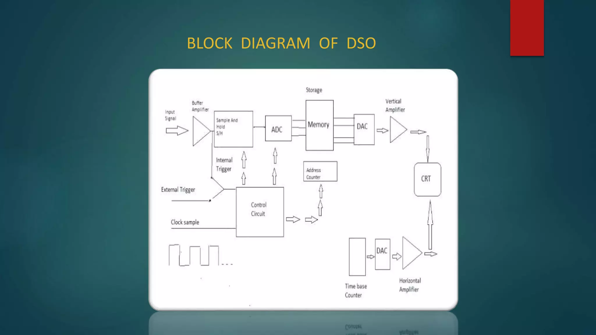
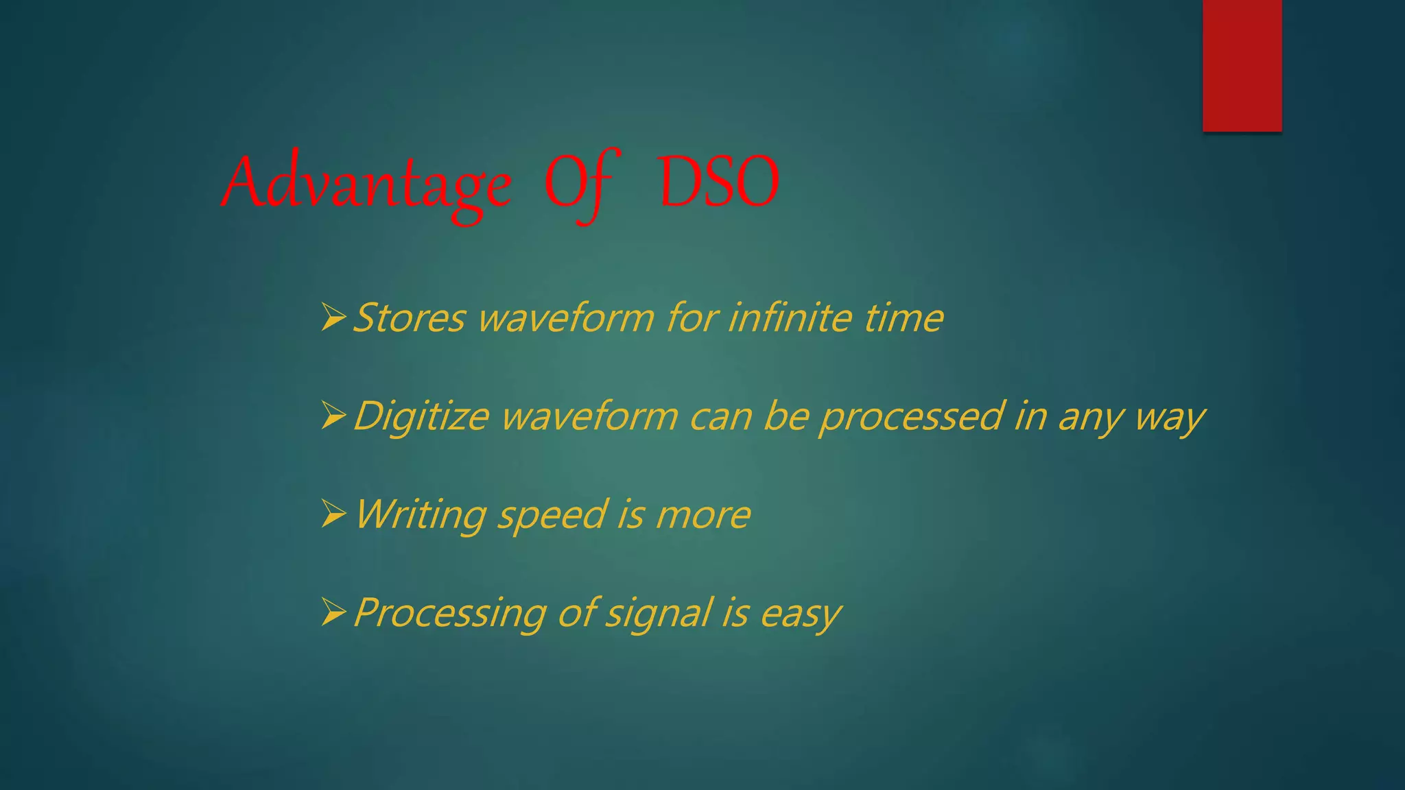
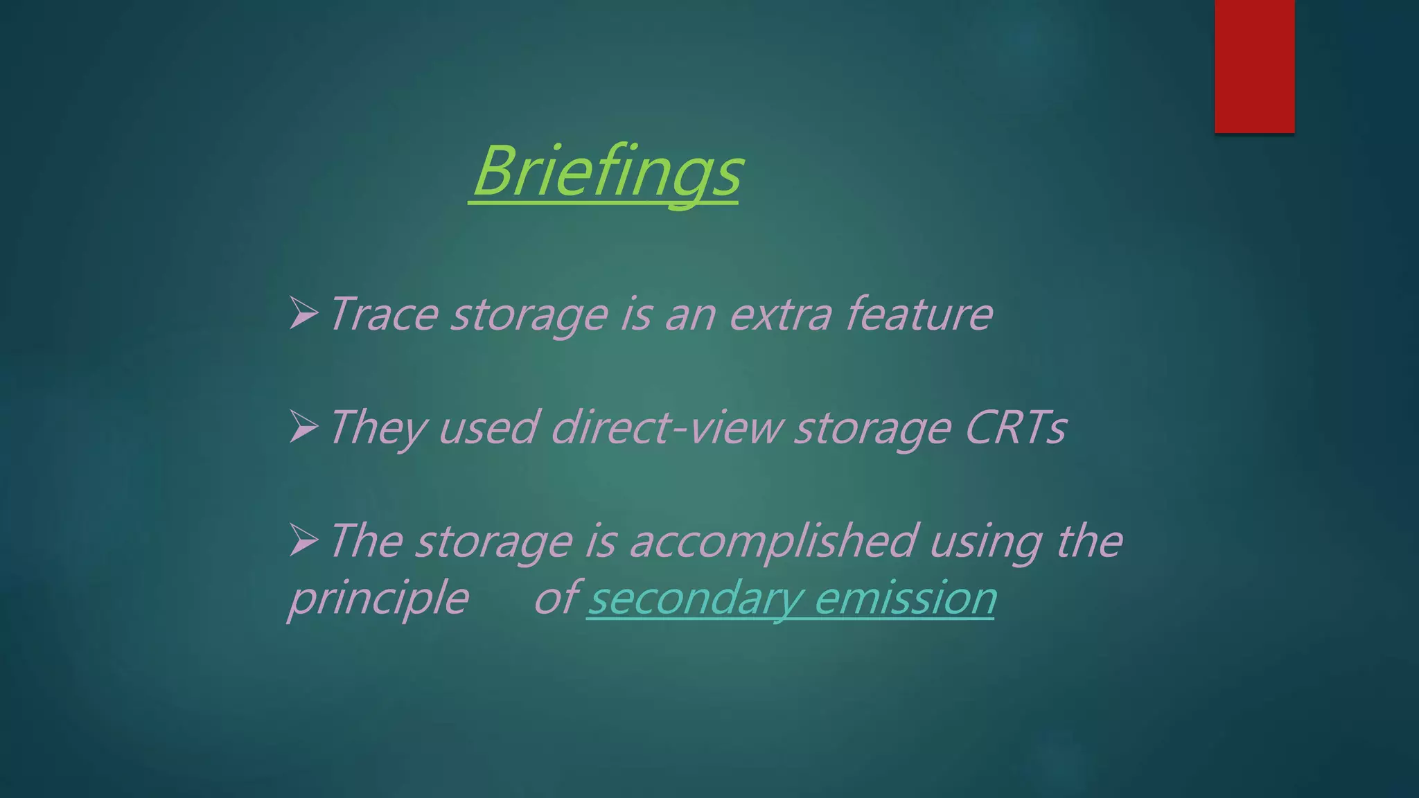
Comparison between Digital Storage Oscilloscope (DSO) and Analog Storage Oscilloscope (ASO), highlighting advantages and storage differences.
Thank you slide.


![Electrical measurement & measuring instruments [emmi (nee-302) -unit-5]](https://cdn.slidesharecdn.com/ss_thumbnails/electricalmeasurementmeasuringinstrumentsemmi-nee-302-unit-5-170607091755-thumbnail.jpg?width=640&height=640&fit=bounds)


