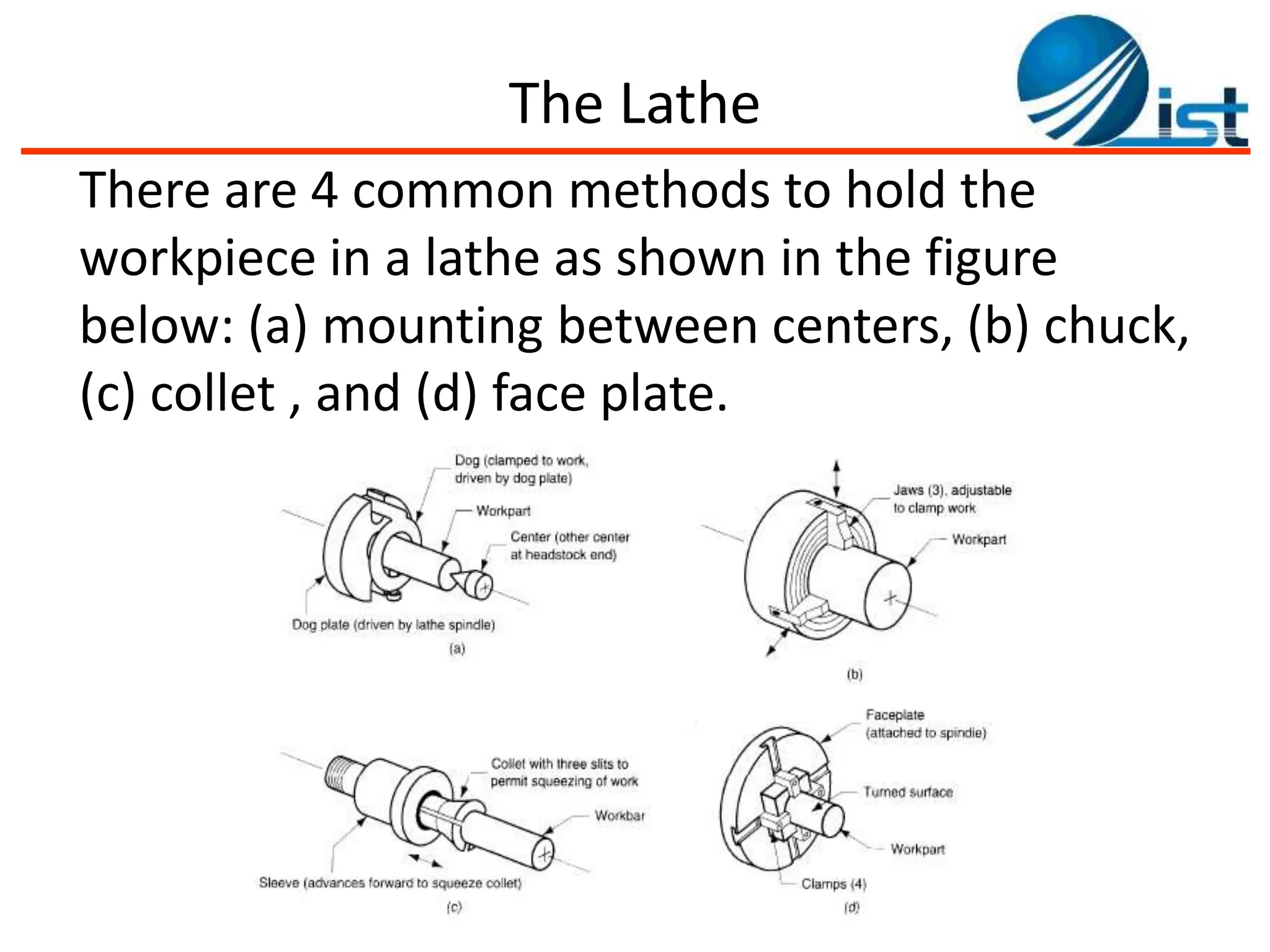
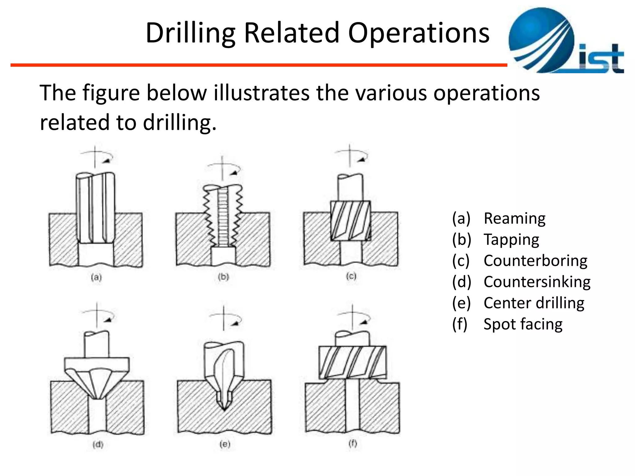
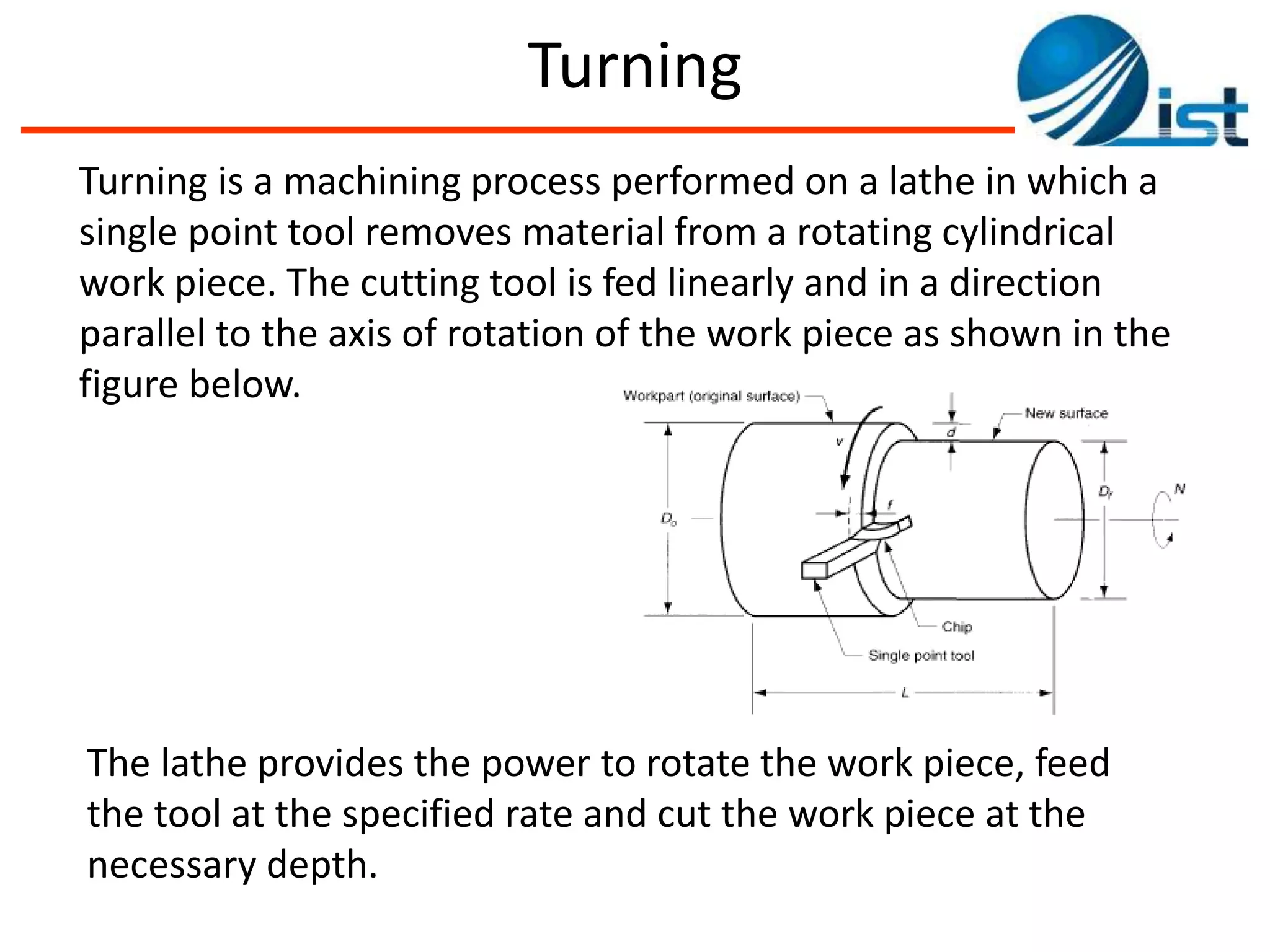
The document discusses various manufacturing processes including lathe, milling, drilling, and turning operations. It provides details on the main components and processes for lathe, milling, and drilling machines. For lathe, it describes the headstock, tailstock, tool post, carriage, and ways. For milling, it covers peripheral, face, up, and down milling. For drilling, it outlines drilling tools, drill presses, and related operations like reaming and tapping. It also includes analysis of machining processes and example problems.
Whole lathe machine in brief which any one can understand easily and quickly.
A Perfect ppt to get knowledge about lathe machine, its parts, operations etc.
This chapter aims to provide basic backgrounds of different types of machining processes and highlights on an understanding of important parameters which affects machining of metals with their chip removals.
Metal cutting or Machining is the process of producing workpiece by removing unwanted material from a block of metal. in the form of chips. This process is most important since almost all the products get their final shape and size by metal removal. either directly or indirectly.
The major drawback of the process is loss of material in the form of chips. In this chapter. we shall have a fundamental understanding of the basic metal process.
Theory of Metal cutting - Principles of Metal cutting, orthogonal and oblique cutting, Merchant circle diagram, cutting forces, power requirements, Economics of machining,problems
This presentation contains various aspects of metal cutting like mechanics of chip formation, single point cutting tool, chip breakers, types of chips,etc
Manufacturing Engineering 2, cutting tools and tool holdersGaurav Mistry
Detail study of cutting tool materials, some special materials, carbide tip tools, carbide inserts, types, carbide insert holders, ISO designation of carbide inserts, single point cutting tool nomenclature and angles, tool geometry, Tool life, tool wear and types, machinability
Design of Stage Progressive Die for a Sheet Metal Component STAY CURIOUS
Progressive die stamping is a metal forming process widely used to produce parts for various industries, such as automotive, electronics and appliances. Progressive die stamping consists of several individual work stations, each of which performs one or more different operations on the part.
MILLING – Cutting parameters, machine time calculation
Milling operation – Plain milling, side & face milling, form milling, gang milling, end milling, face milling, T slot milling, slitting
GEAR CUTTING – Gear cutting on milling machine – dividing head and indexing method, gear hobbing, principle of operation, advantages & limitation, hobbing tech, gear shaping, gear finishing process
Fundamentals of Metal cutting and Machining Processes
MACHINING OPERATIONS AND MACHINING TOOLS
Turning and Related Operations
Drilling and Related Operations
Milling
Machining Centers and Turning Centers
Other Machining Operations
High Speed Machining
COLLEGE BUS MANAGEMENT SYSTEM PROJECT REPORT.pdfKamal Acharya
The College Bus Management system is completely developed by Visual Basic .NET Version. The application is connect with most secured database language MS SQL Server. The application is develop by using best combination of front-end and back-end languages. The application is totally design like flat user interface. This flat user interface is more attractive user interface in 2017. The application is gives more important to the system functionality. The application is to manage the student’s details, driver’s details, bus details, bus route details, bus fees details and more. The application has only one unit for admin. The admin can manage the entire application. The admin can login into the application by using username and password of the admin. The application is develop for big and small colleges. It is more user friendly for non-computer person. Even they can easily learn how to manage the application within hours. The application is more secure by the admin. The system will give an effective output for the VB.Net and SQL Server given as input to the system. The compiled java program given as input to the system, after scanning the program will generate different reports. The application generates the report for users. The admin can view and download the report of the data. The application deliver the excel format reports. Because, excel formatted reports is very easy to understand the income and expense of the college bus. This application is mainly develop for windows operating system users. In 2017, 73% of people enterprises are using windows operating system. So the application will easily install for all the windows operating system users. The application-developed size is very low. The application consumes very low space in disk. Therefore, the user can allocate very minimum local disk space for this application.
Vaccine management system project report documentation..pdfKamal Acharya
The Division of Vaccine and Immunization is facing increasing difficulty monitoring vaccines and other commodities distribution once they have been distributed from the national stores. With the introduction of new vaccines, more challenges have been anticipated with this additions posing serious threat to the already over strained vaccine supply chain system in Kenya.
Explore the innovative world of trenchless pipe repair with our comprehensive guide, "The Benefits and Techniques of Trenchless Pipe Repair." This document delves into the modern methods of repairing underground pipes without the need for extensive excavation, highlighting the numerous advantages and the latest techniques used in the industry.
Learn about the cost savings, reduced environmental impact, and minimal disruption associated with trenchless technology. Discover detailed explanations of popular techniques such as pipe bursting, cured-in-place pipe (CIPP) lining, and directional drilling. Understand how these methods can be applied to various types of infrastructure, from residential plumbing to large-scale municipal systems.
Ideal for homeowners, contractors, engineers, and anyone interested in modern plumbing solutions, this guide provides valuable insights into why trenchless pipe repair is becoming the preferred choice for pipe rehabilitation. Stay informed about the latest advancements and best practices in the field.
Overview of the fundamental roles in Hydropower generation and the components involved in wider Electrical Engineering.
This paper presents the design and construction of hydroelectric dams from the hydrologist’s survey of the valley before construction, all aspects and involved disciplines, fluid dynamics, structural engineering, generation and mains frequency regulation to the very transmission of power through the network in the United Kingdom.
Author: Robbie Edward Sayers
Collaborators and co editors: Charlie Sims and Connor Healey.
(C) 2024 Robbie E. Sayers
About
Indigenized remote control interface card suitable for MAFI system CCR equipment. Compatible for IDM8000 CCR. Backplane mounted serial and TCP/Ethernet communication module for CCR remote access. IDM 8000 CCR remote control on serial and TCP protocol.
• Remote control: Parallel or serial interface.
• Compatible with MAFI CCR system.
• Compatible with IDM8000 CCR.
• Compatible with Backplane mount serial communication.
• Compatible with commercial and Defence aviation CCR system.
• Remote control system for accessing CCR and allied system over serial or TCP.
• Indigenized local Support/presence in India.
• Easy in configuration using DIP switches.
Technical Specifications
Indigenized remote control interface card suitable for MAFI system CCR equipment. Compatible for IDM8000 CCR. Backplane mounted serial and TCP/Ethernet communication module for CCR remote access. IDM 8000 CCR remote control on serial and TCP protocol.
Key Features
Indigenized remote control interface card suitable for MAFI system CCR equipment. Compatible for IDM8000 CCR. Backplane mounted serial and TCP/Ethernet communication module for CCR remote access. IDM 8000 CCR remote control on serial and TCP protocol.
• Remote control: Parallel or serial interface
• Compatible with MAFI CCR system
• Copatiable with IDM8000 CCR
• Compatible with Backplane mount serial communication.
• Compatible with commercial and Defence aviation CCR system.
• Remote control system for accessing CCR and allied system over serial or TCP.
• Indigenized local Support/presence in India.
Application
• Remote control: Parallel or serial interface.
• Compatible with MAFI CCR system.
• Compatible with IDM8000 CCR.
• Compatible with Backplane mount serial communication.
• Compatible with commercial and Defence aviation CCR system.
• Remote control system for accessing CCR and allied system over serial or TCP.
• Indigenized local Support/presence in India.
• Easy in configuration using DIP switches.
Immunizing Image Classifiers Against Localized Adversary Attacksgerogepatton
This paper addresses the vulnerability of deep learning models, particularly convolutional neural networks
(CNN)s, to adversarial attacks and presents a proactive training technique designed to counter them. We
introduce a novel volumization algorithm, which transforms 2D images into 3D volumetric representations.
When combined with 3D convolution and deep curriculum learning optimization (CLO), itsignificantly improves
the immunity of models against localized universal attacks by up to 40%. We evaluate our proposed approach
using contemporary CNN architectures and the modified Canadian Institute for Advanced Research (CIFAR-10
and CIFAR-100) and ImageNet Large Scale Visual Recognition Challenge (ILSVRC12) datasets, showcasing
accuracy improvements over previous techniques. The results indicate that the combination of the volumetric
input and curriculum learning holds significant promise for mitigating adversarial attacks without necessitating
adversary training.
Welcome to WIPAC Monthly the magazine brought to you by the LinkedIn Group Water Industry Process Automation & Control.
In this month's edition, along with this month's industry news to celebrate the 13 years since the group was created we have articles including
A case study of the used of Advanced Process Control at the Wastewater Treatment works at Lleida in Spain
A look back on an article on smart wastewater networks in order to see how the industry has measured up in the interim around the adoption of Digital Transformation in the Water Industry.
Quality defects in TMT Bars, Possible causes and Potential Solutions.PrashantGoswami42
Maintaining high-quality standards in the production of TMT bars is crucial for ensuring structural integrity in construction. Addressing common defects through careful monitoring, standardized processes, and advanced technology can significantly improve the quality of TMT bars. Continuous training and adherence to quality control measures will also play a pivotal role in minimizing these defects.
2. Contents of this lecture:
• Main parts and process of Lathe Machine
• Main parts and process of Milling Machine
• Main parts and processes of Drilling Machine
• Main parts and processes and Turning
• Introduction to Shaper and Planner Machines
(Refer to the Book Groover’s Fundamentals of Modern
Manufacturing Materials, Processes and Systems – Chapter 22)
• Engineering Analysis of Machining Processes
3. 3
The figure to the left shows the principal
components of an engine lathe. The drive
unit used to rotate the spindle is enclosed
in the headstock. The spindle rotates the
work piece. The tailstock is occasionally
used to support one end of the work piece.
The engine lathe is a manually operated machine tool
which is widely used in low to medium production.
Initially, these machine tools were powered by steam
engines, hence the term “engine” lathe.
The Lathe
4. The Lathe
The cutting tool is held in the tool post. The tool post is
mounted on the cross-slide. The cross-slide is mounted on
the carriage. The carriage slides along the ways. The ways
are built into the bed of the lathe.
The carriage moves in a direction parallel to the axis of
rotation and controls the feed rate of the tool. The cross-
slide feeds perpendicular to the work piece.
Thus, by moving the carriage, a turning operation can be
performed; by moving the cross-slide a facing operation can
be carried out.
5. 5
The Lathe
The size of a lathe is determined by its swing and
maximum distance between centers.
The swing of a lathe is the maximum diameter of the
work piece that can be rotated in the spindle.
The maximum distance between centers is the
maximum length of a work piece that can be
mounted between the centers of the headstock and
tailstock.
6. The Lathe
There are 4 common methods to hold the
workpiece in a lathe as shown in the figure
below: (a) mounting between centers, (b) chuck,
(c) collet , and (d) face plate.
7. Milling Operation
• Milling is one of the basic machining processes, which
uses multi-tooth tool that produces number of chips per
revolution and machines a wide variety of part
geometries.
• In Milling the work piece is fed past a rotating cylindrical
tool
• The axis of rotation of the cutting tool is perpendicular
to the direction of feed.
8. CLASSIFICATION OF MILLING
Peripheral Milling
• In peripheral milling, the milled surface is generated by teeth located on
the periphery of the cutter body. The axis of cutter rotation is generally
in a plane parallel to the work piece surface to be machined.
Face Milling
• In face milling, the cutter is mounted on a spindle having an axis of
rotation perpendicular to the work piece surface. The milled surface
results from the action of cutting edges located on the periphery and
face of the cutter.
10. METHODS OF MILLING
Up Milling
• Up milling is also referred to as conventional milling. The direction of the
cutter rotation opposes the feed motion. For example, if the cutter
rotates clockwise , the work piece is fed to the right in up milling.
This is milling “against the feed”.
Down Milling
• Down milling is also referred to as climb milling. The direction of cutter
rotation is same as the feed motion. For example, if the cutter rotates
counterclockwise , the work piece is fed to the right in down milling.
it is milling with the feed.
11. METHODS OF MILLING
• The cutter teeth tend to “pull” the work into the cutter. This
results in a small feed force and about 20% less Hp than
conventional milling. This method can “pull” the work into the
cutter and scrap the work and/or damage the fixture and tool.
• Tool life is also higher with climb milling.
13. Milling Cutters
• A milling cutter is a cutting tool that is used on a milling machine.
Milling cutters are available in many standard and special types,
forms, diameters, and widths. The teeth maybe straight (parallel
to the axis of rotation) or at a helix angle. The cutter may be right-
hand (to turn clockwise) or left-hand (to turn counterclockwise).
Left hand spiral
right hand spiral
Fig. 5 Left and right hand cutters.
Helical
Plain
Fig. 6 Milling Cutters. a ) Helical b ) Plain
15. Other Milling Operations
Several types of Peripheral Milling are :
a. Slab Milling:
It is the basic form of peripheral milling in which the cutter width extends beyond
the work piece on both sides.
b. Slotting:
also called slot milling, in which the width of the cutter is less than the work piece
width, creating a slot in the work—when the cutter is very thin, this operation can be
used to mill narrow slots or cut a work part in two, called saw milling;
c. Side Milling:
Milling process in which the cutter machines the side of the work piece;
d. Straddle Milling:
It is same as side milling, only cutting takes place on both sides of the work
e. Form Milling:
Process in which the milling teeth have a of peripheral milling are special profile that
determines the shape of the slot that is cut in the work
17. Other Milling Operations
Various forms of Face Milling are:
a. Conventional Face Milling:
The Process in which the diameter of the cutter is greater than the work part width, so the
cutter overhangs the work on both sides.
b. Partial face milling:
where the cutter overhangs the work on only one side
c. End Milling:
in which the cutter diameter is less than the work width, so a slot is cut into the part
d. Profile Milling:
A form of end milling in which the outside periphery of a flat part is cut
e. Pocket Milling:
Another form of end milling used to mill shallow pockets into flat parts; and
f. Surface Contouring:
In which a ball-nose cutter (rather than square-end cutter) is fed back and forth across the work
along a curvilinear path at close intervals to create a three dimensional surface form.
19. 19
Drilling
Drilling is used to create round holes in work pieces using a
rotating tool with two cutting edges. This rotating tool is called a
drill or drill bit. This operation is normally performed on a drill
press.
Two types of holes can be made:
– through holes, in which the drill exits the opposite side of the work
– blind holes , in which the drill does not exit
(a) (b)
Figure depicting
(a) through holes and
(b) blind holes
20. Drilling Tool
The figure below depicts a twist drill – the most
commonly used drill bit.
Twist drill bit
22. 22
The body of a twist drill has two spiral flutes which usually have a
30° helical angle. These flutes act as a passageway for chip
extraction from the hole and for coolant to enter the hole
(however, cooling is not effective since chips and coolant move in
opposite directions).
The thickness of the drill between the flutes, also called the web,
provides support over the length of the drill body.
The point of the twist drill is in the shape of a cone and the point
angle is typically 118°.
Drilling Tool
23. 23
Drilling Tool
The twist drill is fed into the work piece while rotating and the
relative motion between the cutting edges of the drill and the
work piece results in material removal and, hence, chip
formation.
The flutes provide enough clearance to allow the chips to be
extracted. During drilling, however, friction between the chip and
cutting surface (rake face) as well as between the outer diameter
of the drill and work piece generates a large amount of heat and,
thus, the temperature of the work piece and drill increases
dramatically.
24. Drilling
To solve the temperature rise problem, the following is
common:
• Peck drilling: the drill is periodically withdrawn from the hole to clear
chips
• Some drills have internal holes in the drill body through which cutting
fluid is delivered to the cutting interface.
Increasing flute size makes it easier to clear chips from
the hole but results in smaller web thickness and affects
the drill rigidity (the opposite is also true).
24
25. 25
The drill press is the most commonly used machine tool for drilling and the
related operations mentioned previously. The most common drill press, and
also the one used in the lab procedure, is the upright drill press. The base sits
on the floor, has a table for holding the work piece, a head with a powered
spindle for the cutting tool, and a bed and column for support.
Figure showing
upright drill press
The Drill Press
27. 27
Drilling
Drills are limited to a depth of no greater than 4
times its diameter because of the high
temperature and the high load on the drilling bit,
which:
• Decreases the strength of the drill and makes it
easier to break.
• Negatively affects the surface finish of the hole.
• Increases the deflection in the drill, which affects
the straightness and dimensional accuracy of the
hole
28. 28
Drilling
Prior to drilling, centering (or center drilling) is used to
create a starter hole (using a center drill). This is used
to:
• Define the location of the hole.
• Solve the “Walking” or “Wandering” problem which
happens because of drill deflection before the chisel
penetrates the work piece.
29. Analysis of Drilling Operation
Cutting Speed:
• The cutting speed in a drilling operation is the surface speed at the outside
diameter of the drill. V in drilling is not a constant along the major cutting edge as
opposed to the other machining operations. It is zero at the center of the twist
drill, and has a maximum value at the drill corner.
Feed:
• Feed f in drilling is specified in mm/rev (in/rev).
Machining Time:
• For Through holes:
t =work thickness, mm (in); fr=feed rate,mm/min (in/min); and A = an approach
allowance that accounts for the drill point angle
30. Analysis of Drilling Operation
• Approach Area Allowance:
where A = approach allowance, mm (in); and = drill point angle. In drilling a
through hole
Machining Time:
• For Blind holes:
31. Analysis of Drilling Operation
Drilling MRR.
• The rate of metal removal in drilling is determined as the product of the
drill cross-sectional area and the feed rate
• This equation is valid only after the drill reaches full diameter and excludes
the initial approach of the drill into the work.
32. Problem-01
• A drilling operation is to be performed with a 12.7 mm diameter twist drill
in a steel work part. The hole is a blind hole at a depth of 60 mm and the
point angle is 118°. The cutting speed is 25 m/min and the feed is 0.30
mm/rev. Determine
(a) the cutting time to complete the drilling operation, and
(b) metal removal rate during the operation, after the drill bit reaches full
diameter.
34. 34
Drilling Related Operations
The following operations are all related to drilling and
can be performed once a hole has been created:
– Reaming: a reamer (usually with multiple straight flutes) is
used to ream a hole, i.e., slightly enlarge a hole and
improve its surface finish and provide tighter tolerances.
– Tapping: a tap is used to create internal screw threads on
an existing hole.
– Counter boring generates a stepped hole, i.e., a larger
diameter hole is created over a smaller diameter hole.
This process is used to seat bolt heads below the surface
of a work piece or flush with the surface.
35. Drilling Related Operations
Operations related to drilling (continued)
– Countersinking is similar to counter boring, but
the hole step is conical and is used for flat head
screws. Countersinking is used also for deburring.
– Spotfacing is similar to milling. This process is
used to provide a flat surface on the work piece.
35
36. 36
Drilling Related Operations
The figure below illustrates the various operations
related to drilling.
(a) Reaming
(b) Tapping
(c) Counterboring
(d) Countersinking
(e) Center drilling
(f) Spot facing
37. Turning
Turning is a machining process performed on a lathe in which a
single point tool removes material from a rotating cylindrical
work piece. The cutting tool is fed linearly and in a direction
parallel to the axis of rotation of the work piece as shown in the
figure below.
The lathe provides the power to rotate the work piece, feed
the tool at the specified rate and cut the work piece at the
necessary depth.
38. Analysis of Turning Operations
38
The three important cutting parameters in turning are:
• The cutting speed v (ft/min): the tangential speed
• The depth of cut d (in): the penetration of the cutting tool
below the original surface of the work.
• The feed f (in/rev): distance (parallel to the axis of rotation)
traveled by the tool per one revolution of the work
39. Analysis of Turning Operations
Material Removal Rate: it is the volume of material removed
per unit time, expressed in mm3/min or in3/min. MRR is
given by:
MRR = πD
avg
d f N
Depth of Cut:
A term used to describe how deep a tool will be set to cut into
the surface or edge of a work piece.
d= (do-df)/2
Feed Rate:
40. Analysis of Turning Operations
• Rotational Speed:
• Time to machine:
• Power Required:
MRR
P
P U
42. Problem # 02
• 1. A cylindrical stainless steel rod with length L=150 mm,
diameter d0 = 12 mm is being reduced in diameter to df =11 mm
by turning on a lathe. The spindle rotates at N = 400 rpm, and
the tool is travelling at an axial speed of υ=200 mm/min
• Calculate:
a. The material removal
rate MRR
b. The cutting time t
c. The power required
if the unit power is estimated to 4 w.s/mm3
43. Solution # 02
• From the information given, the depth of cut is
d = (12 – 11) / 2 = 0.5 mm
• and the feed is
f = υ / Ν
f = 200 / 400 = 0.5 mm/rev
• thus the material removal rate is calculated as
MRR = (π) (Davg) (d) (f) (N)
= (π) (11.5) (0.5) (0.5) (400)
= 3611 mm3/min = 60.2 mm3/s
• b. The cutting time is
t = l / (f. N)
= (150) / (0.5) (400) = 0.75 min
• c. The power required is
Power = (4) (60.2) = 240.8 W
44. Problem # 03
A 150mm long, 75 mm dia rod of titanium alloy being reduced
to 65mm dia by turning on lathe in one pass. Spindle rotates
at 400 rpm and tool travels at axial velocity of 200 mm/min.
Calculate:
1. MRR
2. Cutting time
3. Power required.
45. 45
Turning Operations
– Facing: the tool is fed radially into the rotating work piece to
create a new surface (face) on the end.
– Taper turning: the tool is fed at an angle to the axis of rotation to
create a conical geometry.
– Contour turning: The tool follows a contour that is other than
straight, thus creating a contoured form in the turned part.
– Form turning: a formed cutting tool is fed into the work piece
radially
– Chamfering: the cutting tool cuts an angle on the corner of the
cylinder. A very small chamfer can be used to remove burrs usually
formed during machining processes and to eliminate sharp corners
(for safety reasons).
– Cutoff (or parting): the tool is fed radially (like facing) at some
length along the work piece to cut off the end of the part
46. Turning Operations
– Threading: a pointed tool is fed linearly across the outside
diameter of the work piece (similar to turning) at a large feed
creating external threads on the cylinder
– Boring: a tool is fed linearly and parallel to the axis of rotation to
correct a previously drilled hole and/ or to enlarge the diameter
of an existing hole in the part
– Drilling: drilling can be performed on a lathe by feeding the drill
into the rotating part along its axis.
– Knurling: a knurling tool produces a cross-hatched pattern on the
outer diameter of the work piece
46
48. Engineering Analysis
• Cutting Speed:
It is determined at outside of milling cutter.
• Feed and Feed Rate:
Feed is usually found per teeth of the cutter, also termed as
chip load.
49. Engineering Analysis
• Material Removal Rate in Slab Milling (Peripheral):
It is the product of cross-section of cut and feed rate.
This formula neglects the initial entry of the cutter before full
engagement.
51. Engineering Analysis
• A the approach distance and for Face Milling.
When cutter is center over work piece (a) and when cutter is offset over work
piece (b).