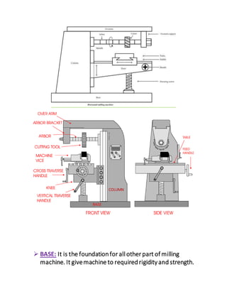
MILLING MACHINE
INTRODUCTION
Milling is a machining process of removal of metal by feeding
the work piece against rotating multipoint cutter. As the
cutter rotate, each cutting edge removes small amount of
material from the work piece. This process is used to generate
flat surfaces or curved profile and many other complex shapes
with great accuracy and having very good surface finish. Based
on spindle position, milling machine are classified into
horizontal milling machine and vertical milling machine.
HORIZONTAL MILLING MACHINE
 BASE: It is the foundationfor all other part of milling
machine. It givemachine to requiredrigidityand strength.
COLUMN
BASE
 COLUMN: It is the vertical member of the machine which
supportedby a table.
 KNEE: It can slides up anddown on the vertical guide ways
of column. It supportedby the elevating screwfor adjusting
the height of the knee.
 SADDLE: It supports andcarries the table. It adjustedon
guide ways on the topof the knee.
 TABLE: It supportthe workpiece andit canmove
longitudinally.
 ELEVATING SCREW: It support theknee and height of the
knee adjustedwiththe help of elevating screw.
 SPINDLE: it help to transmits power from motor to arbor.
 OVERARM: It is onthe topof the column. It provide support
and freeendoverarmcanbe movedhorizontally.
 ARBOR: It is a rodonwhichcutter is mounted. One end of
arbor fit intothe spindle andother end is providedoverarm
support.
MILLING OPERATIONS
Someof the different operations that canbe performedin the
milling machine are,
1)SLAB OR PLAIN MILLING
2) FACE MILLING
3) SIDE MILLING
4) END MILLING
5) T-SLOT MILLING
6) ANGULAR MILLING
7) GEAR MILLING
 PLAIN MILLING
It is alsocalledsurface milling or slabmilling. Plainmilling is use
to produceflat surfaces by placing milling cutter axis parallel to
surfacebeing milled.
 FACE MILLING
In face milling, the cutter is usedis calledface milling cutter. It is a
process whichrotationof face milling cutter is perpendicular to
the work-piecesurfaces
 SIDE MILLING
In side milling,the cutter is usedcalledside milling cutter.It is a
process inwhichproduce a flat surface onthe side of a work
piece.
 END MILLING
In endmilling, the cutter is usedis calledendmilling cutter. The
cutter rotate onvertical to the workpiece. Endmill cutters have
cutting teeth at one end, as well as onthe sides. The edges of end
mill is so weak.So,care shouldbe takenso that the endmill
touch the material slowly as possible.
 T-SLOT MILLING
T-slot is producedusing T-slot cutter. T –slotcutter fedfrom
one end of the work piece after the plainslot cut onthe work
piece using an endmilling cutter. Theneckportionof the
cutter is passes throughthe alreadymilled plainslot.
 ANGULAR MILLING
In angular milling, the cutter is usedcalledangular milling
cutter. It is the process inwhichangular surface are produced
on a work piece.
 GEAR MILLING
In gear milling, gears are producedusing the cutters, these
cutters are called involute gear cutters. These cutters are
manufacturedin many sizes and shapes for different numbers of
teethper gear.
UP MILLING & DOWN MILLING
Based on the direction of the cutter and work piece feed,
milling can be classified into up milling (conventional milling)
and down milling (climb milling).
UP MILLING OR CONVENTIONAL MILLING
In up milling the work piece which is mounted on a table is fed
in the opposite direction of the rotating cutter. That is cutter
rotates against the direction in which the work is being out.
Cutting force vary zero or minimum to maximumso cutting
starts with minimum thickness and maximum at the end of
cut. Surface finishing is poor and more power consumed in up
milling while taking heavy cuts.
DOWN MILLING OR CLIMB MILLING
In down milling, cutter rotate in same direction of that in
which the work is being is out. Job tool motion is same
direction in down milling. In climb milling the chip thickness
varies from a maximum at the start of cut to a minimumat
the end of the cut. Good surface finish obtained in down
milling and less power is consumed.
REFERENCE
 BASIC MECHANICAL ENGINEERING BY J.BENJAMIN
 BASIC MECHANICAL ENGINEERING BY RAJESH KUMAR
 GOOGLE -
mechanicalengineeringstudymaterial.wordpress.com
SUBMITTED TO,
ARUN KAPPEN
ASST.PROFESSOR
MECHANICAL ENGINEERING
MITS.
SUBMITTED BY,
ARUN C S
ROLL NO: 13
COMPUTER SCIENCE
MITS.
Milling machine

Milling machine

  • 1.
    MILLING MACHINE INTRODUCTION Milling isa machining process of removal of metal by feeding the work piece against rotating multipoint cutter. As the cutter rotate, each cutting edge removes small amount of material from the work piece. This process is used to generate flat surfaces or curved profile and many other complex shapes with great accuracy and having very good surface finish. Based on spindle position, milling machine are classified into horizontal milling machine and vertical milling machine. HORIZONTAL MILLING MACHINE
  • 2.
     BASE: Itis the foundationfor all other part of milling machine. It givemachine to requiredrigidityand strength. COLUMN BASE
  • 3.
     COLUMN: Itis the vertical member of the machine which supportedby a table.  KNEE: It can slides up anddown on the vertical guide ways of column. It supportedby the elevating screwfor adjusting the height of the knee.  SADDLE: It supports andcarries the table. It adjustedon guide ways on the topof the knee.  TABLE: It supportthe workpiece andit canmove longitudinally.  ELEVATING SCREW: It support theknee and height of the knee adjustedwiththe help of elevating screw.  SPINDLE: it help to transmits power from motor to arbor.  OVERARM: It is onthe topof the column. It provide support and freeendoverarmcanbe movedhorizontally.  ARBOR: It is a rodonwhichcutter is mounted. One end of arbor fit intothe spindle andother end is providedoverarm support. MILLING OPERATIONS Someof the different operations that canbe performedin the milling machine are, 1)SLAB OR PLAIN MILLING 2) FACE MILLING
  • 4.
    3) SIDE MILLING 4)END MILLING 5) T-SLOT MILLING 6) ANGULAR MILLING 7) GEAR MILLING  PLAIN MILLING It is alsocalledsurface milling or slabmilling. Plainmilling is use to produceflat surfaces by placing milling cutter axis parallel to surfacebeing milled.
  • 5.
     FACE MILLING Inface milling, the cutter is usedis calledface milling cutter. It is a process whichrotationof face milling cutter is perpendicular to the work-piecesurfaces
  • 6.
     SIDE MILLING Inside milling,the cutter is usedcalledside milling cutter.It is a process inwhichproduce a flat surface onthe side of a work piece.
  • 7.
     END MILLING Inendmilling, the cutter is usedis calledendmilling cutter. The cutter rotate onvertical to the workpiece. Endmill cutters have cutting teeth at one end, as well as onthe sides. The edges of end mill is so weak.So,care shouldbe takenso that the endmill touch the material slowly as possible.
  • 8.
     T-SLOT MILLING T-slotis producedusing T-slot cutter. T –slotcutter fedfrom one end of the work piece after the plainslot cut onthe work piece using an endmilling cutter. Theneckportionof the cutter is passes throughthe alreadymilled plainslot.
  • 9.
     ANGULAR MILLING Inangular milling, the cutter is usedcalledangular milling cutter. It is the process inwhichangular surface are produced on a work piece.  GEAR MILLING
  • 10.
    In gear milling,gears are producedusing the cutters, these cutters are called involute gear cutters. These cutters are manufacturedin many sizes and shapes for different numbers of teethper gear. UP MILLING & DOWN MILLING Based on the direction of the cutter and work piece feed, milling can be classified into up milling (conventional milling) and down milling (climb milling). UP MILLING OR CONVENTIONAL MILLING
  • 11.
    In up millingthe work piece which is mounted on a table is fed in the opposite direction of the rotating cutter. That is cutter rotates against the direction in which the work is being out. Cutting force vary zero or minimum to maximumso cutting starts with minimum thickness and maximum at the end of cut. Surface finishing is poor and more power consumed in up milling while taking heavy cuts. DOWN MILLING OR CLIMB MILLING In down milling, cutter rotate in same direction of that in which the work is being is out. Job tool motion is same
  • 12.
    direction in downmilling. In climb milling the chip thickness varies from a maximum at the start of cut to a minimumat the end of the cut. Good surface finish obtained in down milling and less power is consumed. REFERENCE  BASIC MECHANICAL ENGINEERING BY J.BENJAMIN  BASIC MECHANICAL ENGINEERING BY RAJESH KUMAR  GOOGLE - mechanicalengineeringstudymaterial.wordpress.com SUBMITTED TO, ARUN KAPPEN ASST.PROFESSOR MECHANICAL ENGINEERING MITS. SUBMITTED BY, ARUN C S ROLL NO: 13 COMPUTER SCIENCE MITS.