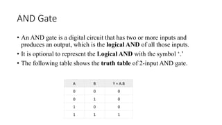
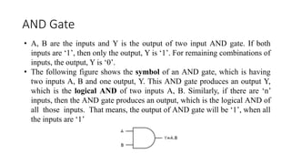
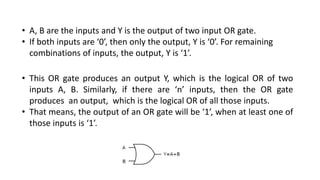
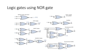
1) Logic gates like AND, OR, NOT, NAND, and NOR are basic digital circuits that perform logical operations on binary inputs and produce binary outputs. Their behavior is defined by truth tables.
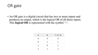
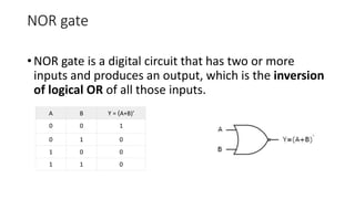
2) AND gates output 1 only when all inputs are 1. OR gates output 1 if any input is 1. NAND and NOR gates are universal gates that can be used to implement all other logic functions.
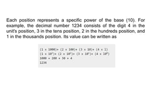
3) Computers use binary number systems like decimal to represent data as strings of 0s and 1s. Decimal uses 10 digits while the position of each digit determines its value and meaning in base-10 numbers.


![DLD_-ASoat(41230301768)basic logic [1].pptx](https://cdn.slidesharecdn.com/ss_thumbnails/dld-asoat412303017681-251220103903-3c4281fc-thumbnail.jpg?width=640&height=640&fit=bounds)


