Downloaded 698 times
![Anatomy of a Process
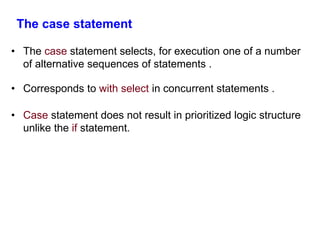
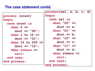
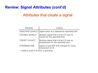
• The process statement is a concurrent statement , which
delineates a part of an architecture where sequential statements
are executed.
• Syntax
[label:] process [(sensitivity list )]
declarations
begin
sequential statements
end process [label];](https://image.slidesharecdn.com/behavioralmodelling-140820102711-phpapp01/85/Behavioral-modelling-in-VHDL-4-320.jpg)
![VHDL Sequential Statements
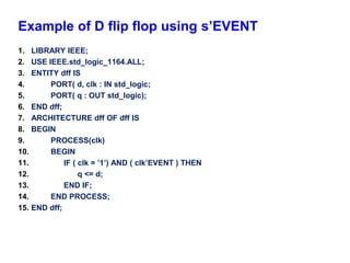
• Assignments executed sequentially in processes
• Sequential statements
– {Signal, variable} assignments
– Flow control
• IF <condition> THEN <statements> [ELSIF <statements] [ELSE
<statements>] END IF;
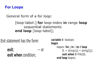
• FOR <range> LOOP <statements> END LOOP;
• WHILE <condition> LOOP <statements> END LOOP;
• CASE <condition> IS WHEN <value> => <statements>
{WHEN <value> => <statements>}
[WHEN others => <statements>]
END CASE;
– WAIT [ON <signal>] [UNTIL <expression>] [FOR <time>] ;
– ASSERT <condition> [REPORT <string>] [SEVERITY <level>] ;](https://image.slidesharecdn.com/behavioralmodelling-140820102711-phpapp01/85/Behavioral-modelling-in-VHDL-13-320.jpg)
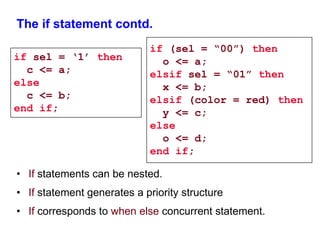
![The if statement
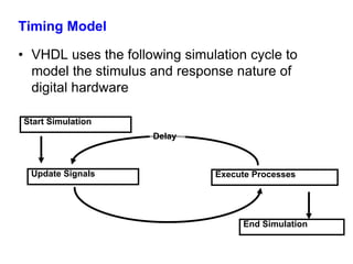
• Syntax
if condition1 then
statements
[elsif condition2 then
statements]
[else
statements]
end if;
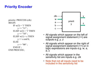
Priority
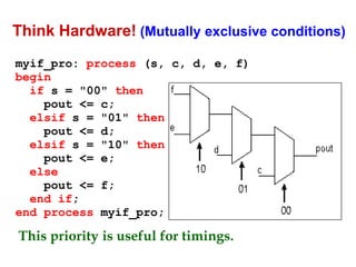
• An if statement selects one or none of a sequence of
events to execute . The choice depends on one or more
conditions.](https://image.slidesharecdn.com/behavioralmodelling-140820102711-phpapp01/85/Behavioral-modelling-in-VHDL-14-320.jpg)
![Loop, While & For Statement
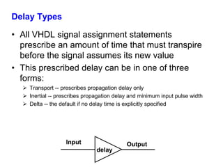
Syntax
[label:] loop
{sequential_statement}
end loop [label];
Syntax
[label:] while condition loop
{sequential_statement}
end loop [label];
Syntax
[label:] for identifier in discrete_range
loop
{sequential_statement}
end loop [label];](https://image.slidesharecdn.com/behavioralmodelling-140820102711-phpapp01/85/Behavioral-modelling-in-VHDL-20-320.jpg)
![Null statement
null_statement::=
[ label : ] null ;
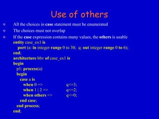
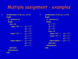
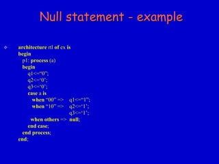
The null - statement explicitly prevents any action from being carried out.
This statement means “do nothing”.
This command can, for example, be used if default signal assignments have
been used in a process and an alternative in the case statement must not change
that value.](https://image.slidesharecdn.com/behavioralmodelling-140820102711-phpapp01/85/Behavioral-modelling-in-VHDL-32-320.jpg)
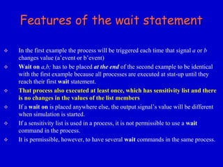
![Wait statement
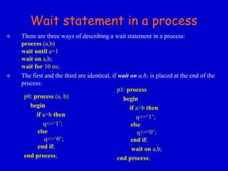
wait_statement::=
[ label : ] wait [ sensitivity_clause ]
[ condition_clause ]
[ timeout_clause ] ;
Examples:
wait ;
The process is permanently interrupted.
wait for 5 ns ;
The process is interrupted for 5 ns.
wait on sig_1, sig_2 ;
The process is interrupted until the value of one of the
two signals changes.
wait until clock = '1' ;
The process is interrupted until the value of clock is 1.](https://image.slidesharecdn.com/behavioralmodelling-140820102711-phpapp01/85/Behavioral-modelling-in-VHDL-34-320.jpg)
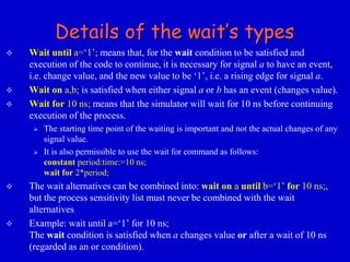
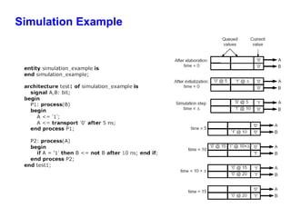
![Simulation results
10 20 30 40 50 60 time [ns]
A
C1
C2
C3
C4
C5
C6
10 ns 20 ns
C7](https://image.slidesharecdn.com/behavioralmodelling-140820102711-phpapp01/85/Behavioral-modelling-in-VHDL-39-320.jpg)
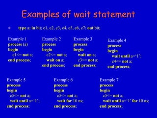
![Inertial Delay
• Provides for specification propagation delay and input
pulse width, i.e. ‘inertia’ of output:
target <= [REJECT time_expression] INERTIAL waveform;
• Inertial delay is default and REJECT is optional:
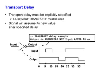
Output <= NOT Input AFTER 10 ns;
-- Propagation delay and minimum pulse width are 10ns
Input
Output
0 5 10 15 20 25 30 35
Input Output](https://image.slidesharecdn.com/behavioralmodelling-140820102711-phpapp01/85/Behavioral-modelling-in-VHDL-50-320.jpg)

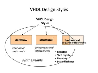
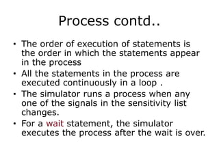
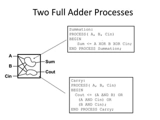
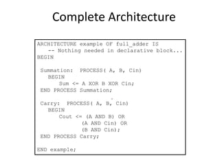
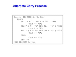
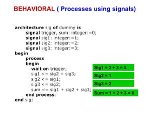
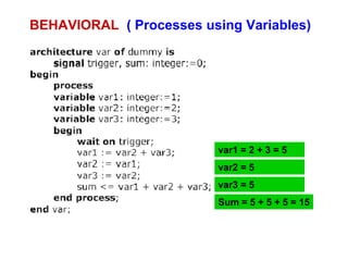
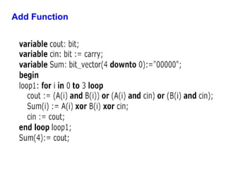
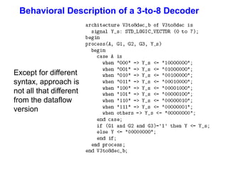
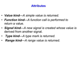
This document discusses behavioral modeling in VHDL. It covers different VHDL design styles including behavioral, dataflow, and structural. Behavioral modeling uses sequential statements inside processes to model functionality. Key concepts covered include processes with and without sensitivity lists, concurrent vs sequential execution, if/case statements, loops, and wait statements. An example of a behavioral model for a full adder is presented using two processes.


![RF Circuit Design - [Ch2-1] Resonator and Impedance Matching](https://cdn.slidesharecdn.com/ss_thumbnails/ch2-1-150613064353-lva1-app6892-thumbnail.jpg?width=640&height=640&fit=bounds)