By
~Nilanjan Ghosh
LOGIC GATES
Logic Gates
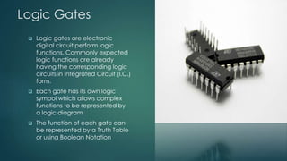
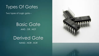
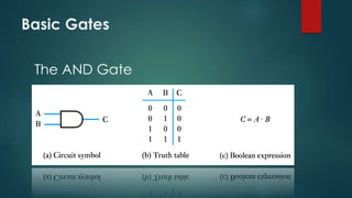
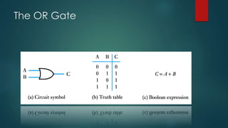
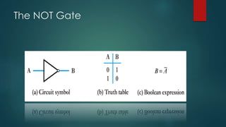
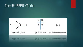
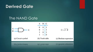
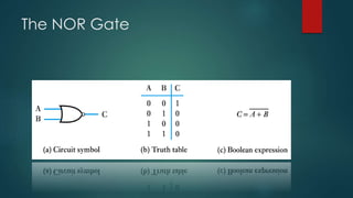
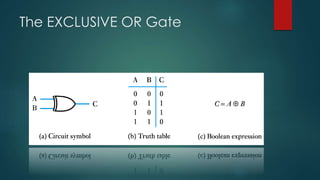
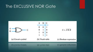
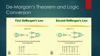
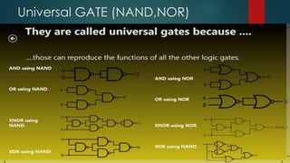
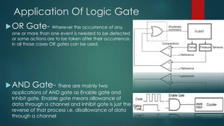
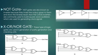
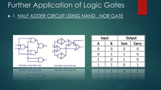
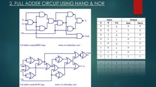
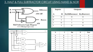
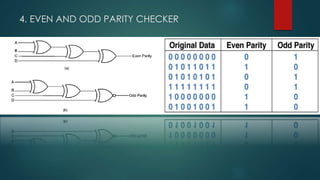
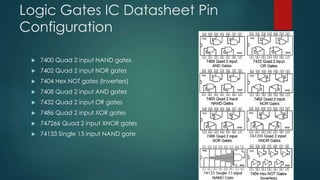
 Logic gates are electronic
digital circuit perform logic
functions. Commonly expected
logic functions are already
having the corresponding logic
circuits in Integrated Circuit (I.C.)
form.
 Each gate has its own logic
symbol which allows complex
functions to be represented by
a logic diagram
 The function of each gate can
be represented by a Truth Table
or using Boolean Notation
Types Of Gates
Two types of Logic gate –
Basic Gate
AND , OR , NOT
Derived Gate
NAND , NOR , XOR
Basic Gates
The AND Gate
The OR Gate
The NOT Gate
The BUFFER Gate
Derived Gate
The NAND Gate
The NOR Gate
The EXCLUSIVE OR Gate
The EXCLUSIVE NOR Gate
De-Morgan’s Theorem and Logic
Conversion
Universal GATE (NAND,NOR)
Application Of Logic Gate
OR Gate- Wherever the occurrence of any
one or more than one event is needed to be detected
or some actions are to be taken after their occurrence,
in all those cases OR gates can be used.
AND Gate- There are mainly two
applications of AND gate as Enable gate and
Inhibit gate. Enable gate means allowance of
data through a channel and Inhibit gate is just the
reverse of that process i.e. disallowance of data
through a channel
NOT Gate- NOT gates are also known as
inverter because they invert the output given to them
and show the reverse result. Now the CMOS inverters
are commonly used to build square wave oscillators
which are used for generating clock signals
X-OR/NOR GATE- These type of logic
gates are used in generation of parity generation and
checking units.
Further Application of Logic Gates
 1. HALF ADDER CIRCUIT USING NAND , NOR GATE
2. FULL ADDER CIRCUIT USING NAND & NOR
3. HALF & FULL SUBTRACTOR CIRCUIT USING NAND & NOR
4. EVEN AND ODD PARITY CHECKER
Logic Gates IC Datasheet Pin
Configuration
 7400 Quad 2 input NAND gates
 7402 Quad 2 input NOR gates
 7404 Hex NOT gates (Inverters)
 7408 Quad 2 input AND gates
 7432 Quad 2 input OR gates
 7486 Quad 2 input XOR gates
 747266 Quad 2 input XNOR gates
 74133 Single 13 input NAND gate
Logic gates

Logic gates

  • 1.
  • 2.
    Logic Gates  Logicgates are electronic digital circuit perform logic functions. Commonly expected logic functions are already having the corresponding logic circuits in Integrated Circuit (I.C.) form.  Each gate has its own logic symbol which allows complex functions to be represented by a logic diagram  The function of each gate can be represented by a Truth Table or using Boolean Notation
  • 3.
    Types Of Gates Twotypes of Logic gate – Basic Gate AND , OR , NOT Derived Gate NAND , NOR , XOR
  • 4.
  • 5.
  • 6.
  • 7.
  • 8.
  • 9.
  • 10.
  • 11.
  • 12.
    De-Morgan’s Theorem andLogic Conversion
  • 13.
  • 14.
    Application Of LogicGate OR Gate- Wherever the occurrence of any one or more than one event is needed to be detected or some actions are to be taken after their occurrence, in all those cases OR gates can be used. AND Gate- There are mainly two applications of AND gate as Enable gate and Inhibit gate. Enable gate means allowance of data through a channel and Inhibit gate is just the reverse of that process i.e. disallowance of data through a channel
  • 15.
    NOT Gate- NOTgates are also known as inverter because they invert the output given to them and show the reverse result. Now the CMOS inverters are commonly used to build square wave oscillators which are used for generating clock signals X-OR/NOR GATE- These type of logic gates are used in generation of parity generation and checking units.
  • 16.
    Further Application ofLogic Gates  1. HALF ADDER CIRCUIT USING NAND , NOR GATE
  • 17.
    2. FULL ADDERCIRCUIT USING NAND & NOR
  • 18.
    3. HALF &FULL SUBTRACTOR CIRCUIT USING NAND & NOR
  • 19.
    4. EVEN ANDODD PARITY CHECKER
  • 20.
    Logic Gates ICDatasheet Pin Configuration  7400 Quad 2 input NAND gates  7402 Quad 2 input NOR gates  7404 Hex NOT gates (Inverters)  7408 Quad 2 input AND gates  7432 Quad 2 input OR gates  7486 Quad 2 input XOR gates  747266 Quad 2 input XNOR gates  74133 Single 13 input NAND gate