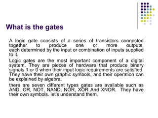
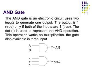
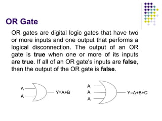
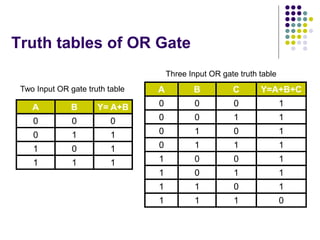
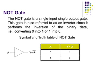
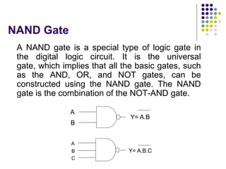
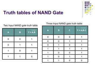
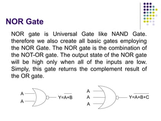
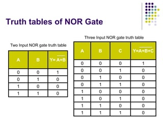
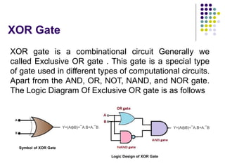
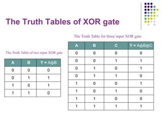
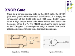
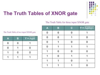
Digital Logic Gates of
Computer Science
Prof. Anil Kumar Prajapati
Govt. Madhav Science PG College
What is the gates
A logic gate consists of a series of transistors connected
together to produce one or more outputs,
each determined by the input or combination of inputs supplied
to it.
Logic gates are the most important component of a digital
system. They are pieces of hardware that produce binary
signals 1 or 0 when their input logic requirements are satisfied.
They have their own graphic symbols, and their operation can
be explained by algebra.
there are seven different types gates are available such as
AND, OR, NOT, NAND, NOR, XOR And XNOR. They have
their own symbols. let's understand them.
Gates
We will understand different logic gates in this
section such as,
 AND Gate
 OR Gate
 NOT Gate
 NAND Gate
 NOR Gate
 XOR Gate
 XNOR Gate
AND Gate
The AND gate is an electronic circuit uses two
inputs to generate one output. The output is 1
(true) only if both of the inputs are 1 (true). The
dot (.) is used to represent the AND operation.
This operation works on multiplication. the gate
also available in three input
A
B
Y= A.B
A
B
C
Y= A.B.C
Truth tables of AND Gate
A B Y = A.B
0 0 0
0 1 0
1 0 0
1 1 1
A B C Y = A.B.C
0 0 0 0
0 0 1 0
0 1 0 0
1 1 1 0
1 0 0 0
1 0 1 0
1 1 0 1
Two Input AND gate truth table
Three Input AND gate truth table
OR Gate
OR gates are digital logic gates that have two
or more inputs and one output that performs a
logical disconnection. The output of an OR
gate is true when one or more of its inputs
are true. If all of an OR gate's inputs are false,
then the output of the OR gate is false.
A
A
A
A
A
Y=A+B Y=A+B+C
Truth tables of OR Gate
A B Y= A+B
0 0 0
0 1 1
1 0 1
1 1 1
A B C Y=A+B+C
0 0 0 1
0 0 1 1
0 1 0 1
0 1 1 1
1 0 0 1
1 0 1 1
1 1 0 1
1 1 1 0
Two Input OR gate truth table
Three Input OR gate truth table
NOT Gate
The NOT gate is a single input single output gate.
This gate is also referred to as an inverter since it
performs the inversion of the binary data,
i.e., converting 0 into 1 or 1 into 0.
Symbol and Truth table of NOT Gate
A
A Y = A
0 1
1 0
Y= A
NAND Gate
A NAND gate is a special type of logic gate in
the digital logic circuit. It is the universal
gate, which implies that all the basic gates, such
as the AND, OR, and NOT gates, can be
constructed using the NAND gate. The NAND
gate is the combination of the NOT-AND gate.
A
B
Y= A.B
A
B
C
Y= A.B.C
Truth tables of NAND Gate
A B Y = A.B
0 0 1
0 1 1
1 0 1
1 1 0
A B C Y = A.B.C
0 0 0 1
0 0 1 1
0 1 0 1
1 1 1 1
1 0 0 1
1 0 1 1
1 1 0 0
Two Input NAND gate truth table
Three Input NAND gate truth table
NOR Gate
A
A
A
A
A
Y=A+B Y=A+B+C
NOR gate is Universal Gate like NAND Gate.
therefore we also create all basic gates employing
the NOR Gate. The NOR gate is the combination of
the NOT-OR gate. The output state of the NOR gate
will be high only when all of the inputs are low.
Simply, this gate returns the complement result of
the OR gate.
Truth tables of NOR Gate
A B Y= A+B
0 0 1
0 1 0
1 0 0
1 1 0
A B C Y=A+B+C
0 0 0 1
0 0 1 0
0 1 0 0
0 1 1 0
1 0 0 0
1 0 1 0
1 1 0 0
1 1 1 0
Two Input NOR gate truth table
Three Input NOR gate truth table
XOR Gate
XOR gate is a combinational circuit Generally we
called Exclusive OR gate . This gate is a special type
of gate used in different types of computational circuits.
Apart from the AND, OR, NOT, NAND, and NOR gate.
The Logic Diagram Of Exclusive OR gate is as follows
Y=(A⨁B)=¯A.B+A.¯B Y=(A⨁B)=¯A.B+A.¯B
Symbol of XOR Gate
Logic Design of XOR Gate
The Truth Tables of XOR gate
A B Y = A⨁B
0 0 0
0 1 1
1 0 1
1 1 0
A B C Y = A⨁B⨁C
0 0 0 0
0 0 1 1
0 1 0 1
0 1 1 0
1 0 0 1
1 0 1 0
1 1 0 0
1 1 1 1
The Truth Table of two input XOR gate
The Truth Table for three input XOR gate
XNOR Gate
There is a complementary gate to the XOR gate, the XNOR
gate. Both gates share a common characteristic. It is simply the
combination of the XOR gate and NOT gate. XNOR gates
result in high output levels only when both of their inputs are
the same, either 0 or 1. The XNOR gate has the same symbol
as the XOR gate, but a complement sign is added. The XNOR
gate is sometimes referred to as the Equivalence gate.
Symbol of XNOR Gate
Logic Design of XNOR Gate
The Truth Tables of XNOR gate
A B Y = A⨁B
0 0 1
0 1 0
1 0 0
1 1 1
A B C Y = A⨁B⨁C
0 0 0 1
0 0 1 0
0 1 0 0
0 1 1 1
1 0 0 0
1 0 1 1
1 1 0 1
1 1 1 0
The Truth Table of two input XNOR gate
The Truth Table for three input XNOR gate
Thanks and Regards:
Anil Kumar Prajapati
Assistant Professor: Computer Science

Digital logic Gates of Computer Science

  • 1.
    Digital Logic Gatesof Computer Science Prof. Anil Kumar Prajapati Govt. Madhav Science PG College
  • 2.
    What is thegates A logic gate consists of a series of transistors connected together to produce one or more outputs, each determined by the input or combination of inputs supplied to it. Logic gates are the most important component of a digital system. They are pieces of hardware that produce binary signals 1 or 0 when their input logic requirements are satisfied. They have their own graphic symbols, and their operation can be explained by algebra. there are seven different types gates are available such as AND, OR, NOT, NAND, NOR, XOR And XNOR. They have their own symbols. let's understand them.
  • 3.
    Gates We will understanddifferent logic gates in this section such as,  AND Gate  OR Gate  NOT Gate  NAND Gate  NOR Gate  XOR Gate  XNOR Gate
  • 4.
    AND Gate The ANDgate is an electronic circuit uses two inputs to generate one output. The output is 1 (true) only if both of the inputs are 1 (true). The dot (.) is used to represent the AND operation. This operation works on multiplication. the gate also available in three input A B Y= A.B A B C Y= A.B.C
  • 5.
    Truth tables ofAND Gate A B Y = A.B 0 0 0 0 1 0 1 0 0 1 1 1 A B C Y = A.B.C 0 0 0 0 0 0 1 0 0 1 0 0 1 1 1 0 1 0 0 0 1 0 1 0 1 1 0 1 Two Input AND gate truth table Three Input AND gate truth table
  • 6.
    OR Gate OR gatesare digital logic gates that have two or more inputs and one output that performs a logical disconnection. The output of an OR gate is true when one or more of its inputs are true. If all of an OR gate's inputs are false, then the output of the OR gate is false. A A A A A Y=A+B Y=A+B+C
  • 7.
    Truth tables ofOR Gate A B Y= A+B 0 0 0 0 1 1 1 0 1 1 1 1 A B C Y=A+B+C 0 0 0 1 0 0 1 1 0 1 0 1 0 1 1 1 1 0 0 1 1 0 1 1 1 1 0 1 1 1 1 0 Two Input OR gate truth table Three Input OR gate truth table
  • 8.
    NOT Gate The NOTgate is a single input single output gate. This gate is also referred to as an inverter since it performs the inversion of the binary data, i.e., converting 0 into 1 or 1 into 0. Symbol and Truth table of NOT Gate A A Y = A 0 1 1 0 Y= A
  • 9.
    NAND Gate A NANDgate is a special type of logic gate in the digital logic circuit. It is the universal gate, which implies that all the basic gates, such as the AND, OR, and NOT gates, can be constructed using the NAND gate. The NAND gate is the combination of the NOT-AND gate. A B Y= A.B A B C Y= A.B.C
  • 10.
    Truth tables ofNAND Gate A B Y = A.B 0 0 1 0 1 1 1 0 1 1 1 0 A B C Y = A.B.C 0 0 0 1 0 0 1 1 0 1 0 1 1 1 1 1 1 0 0 1 1 0 1 1 1 1 0 0 Two Input NAND gate truth table Three Input NAND gate truth table
  • 11.
    NOR Gate A A A A A Y=A+B Y=A+B+C NORgate is Universal Gate like NAND Gate. therefore we also create all basic gates employing the NOR Gate. The NOR gate is the combination of the NOT-OR gate. The output state of the NOR gate will be high only when all of the inputs are low. Simply, this gate returns the complement result of the OR gate.
  • 12.
    Truth tables ofNOR Gate A B Y= A+B 0 0 1 0 1 0 1 0 0 1 1 0 A B C Y=A+B+C 0 0 0 1 0 0 1 0 0 1 0 0 0 1 1 0 1 0 0 0 1 0 1 0 1 1 0 0 1 1 1 0 Two Input NOR gate truth table Three Input NOR gate truth table
  • 13.
    XOR Gate XOR gateis a combinational circuit Generally we called Exclusive OR gate . This gate is a special type of gate used in different types of computational circuits. Apart from the AND, OR, NOT, NAND, and NOR gate. The Logic Diagram Of Exclusive OR gate is as follows Y=(A⨁B)=¯A.B+A.¯B Y=(A⨁B)=¯A.B+A.¯B Symbol of XOR Gate Logic Design of XOR Gate
  • 14.
    The Truth Tablesof XOR gate A B Y = A⨁B 0 0 0 0 1 1 1 0 1 1 1 0 A B C Y = A⨁B⨁C 0 0 0 0 0 0 1 1 0 1 0 1 0 1 1 0 1 0 0 1 1 0 1 0 1 1 0 0 1 1 1 1 The Truth Table of two input XOR gate The Truth Table for three input XOR gate
  • 15.
    XNOR Gate There isa complementary gate to the XOR gate, the XNOR gate. Both gates share a common characteristic. It is simply the combination of the XOR gate and NOT gate. XNOR gates result in high output levels only when both of their inputs are the same, either 0 or 1. The XNOR gate has the same symbol as the XOR gate, but a complement sign is added. The XNOR gate is sometimes referred to as the Equivalence gate. Symbol of XNOR Gate Logic Design of XNOR Gate
  • 16.
    The Truth Tablesof XNOR gate A B Y = A⨁B 0 0 1 0 1 0 1 0 0 1 1 1 A B C Y = A⨁B⨁C 0 0 0 1 0 0 1 0 0 1 0 0 0 1 1 1 1 0 0 0 1 0 1 1 1 1 0 1 1 1 1 0 The Truth Table of two input XNOR gate The Truth Table for three input XNOR gate
  • 17.
    Thanks and Regards: AnilKumar Prajapati Assistant Professor: Computer Science