Downloaded 34 times
![Process statement
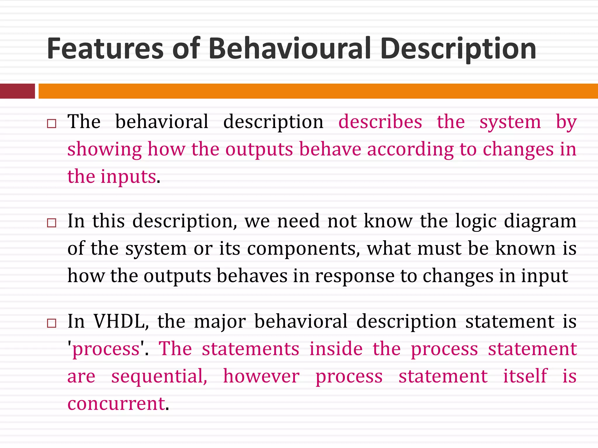
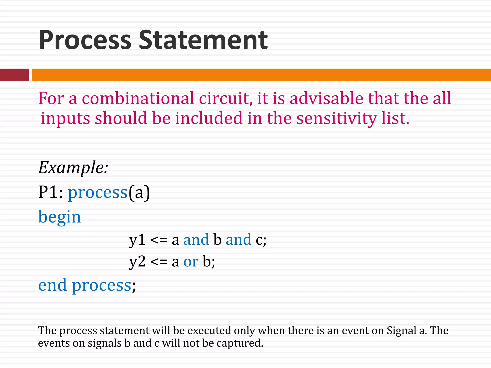
A process statement contains sequential statements that describe
the functionality of a portion of an entity in sequential terms
Syntax:
[ process-label: ] process [ ( sensitivity-list ) ]
[process-item-declarations]
begin
.
.
sequential-statements;
.
.
.
end process [ process-label];
variable-assignment-statement,
signal-assignment-statement,
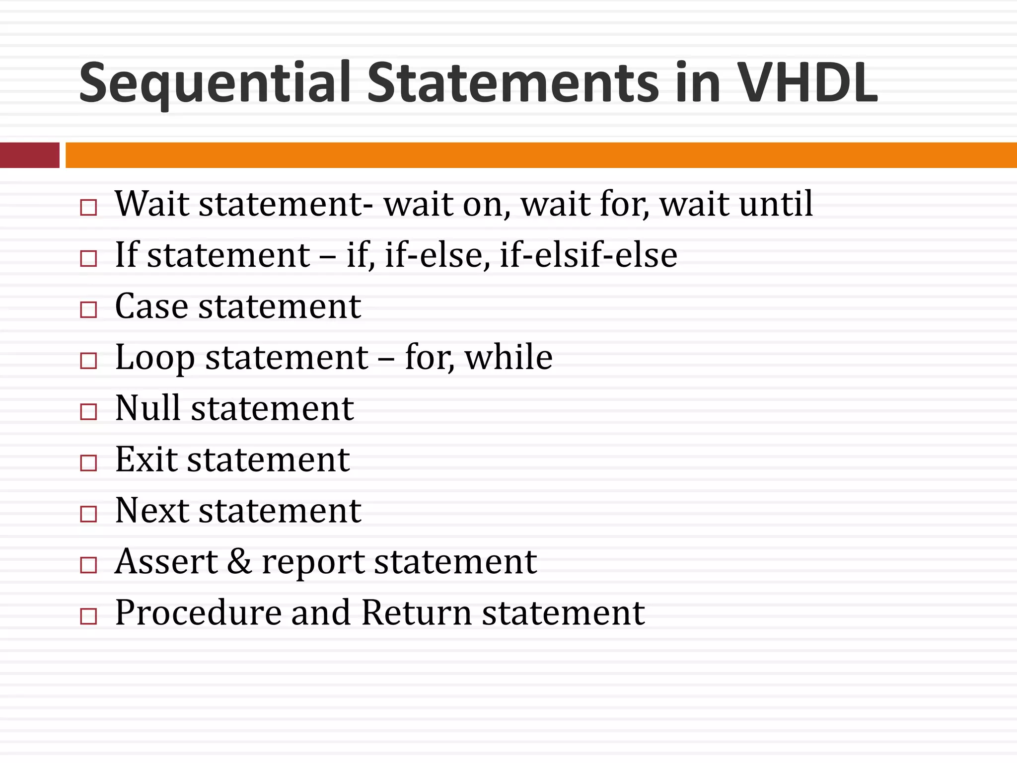
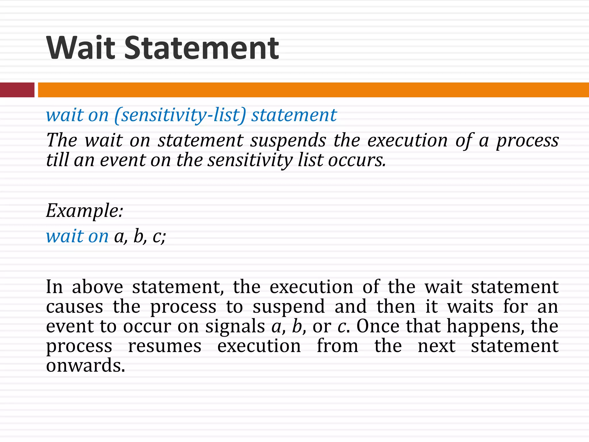
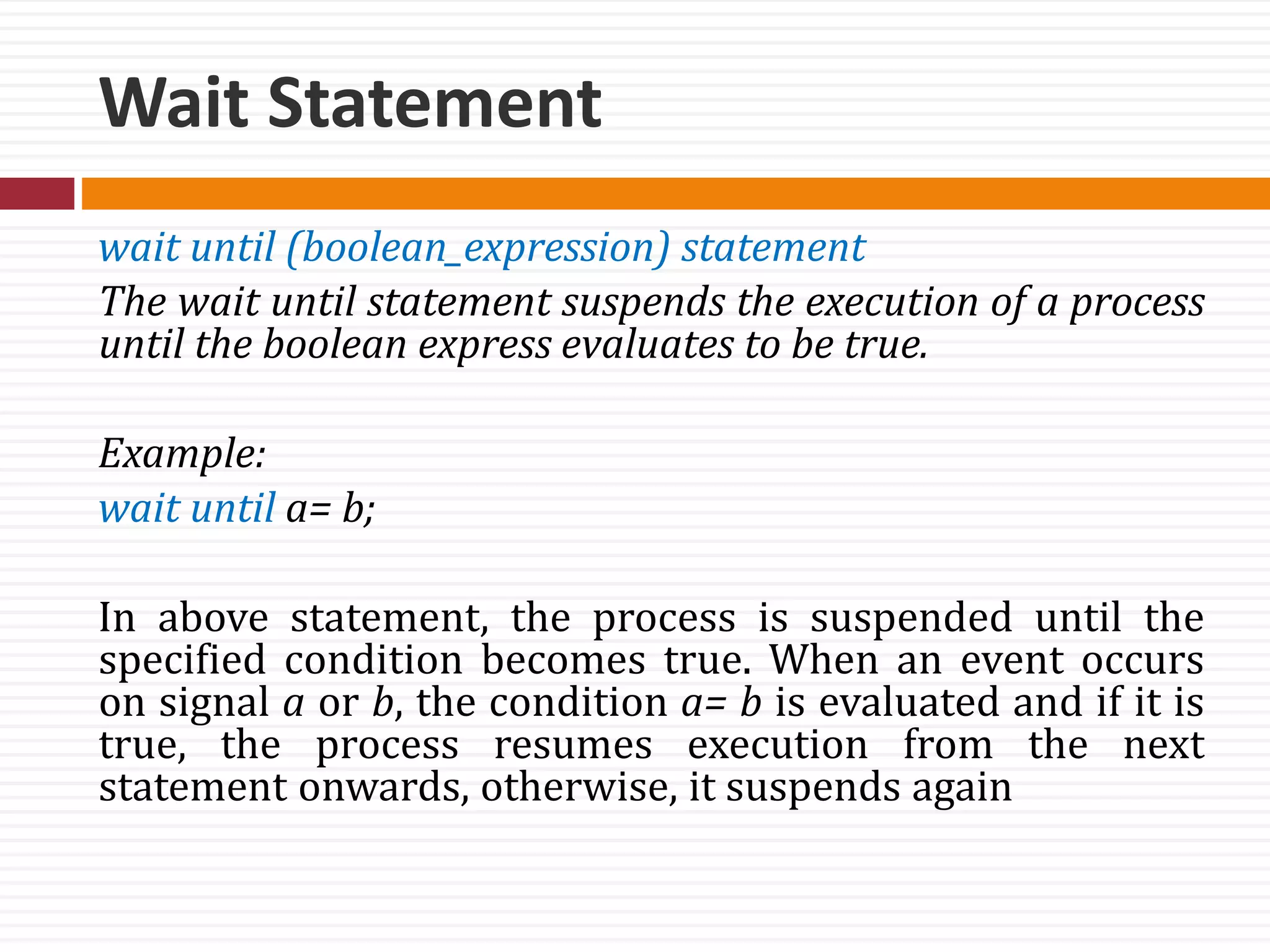
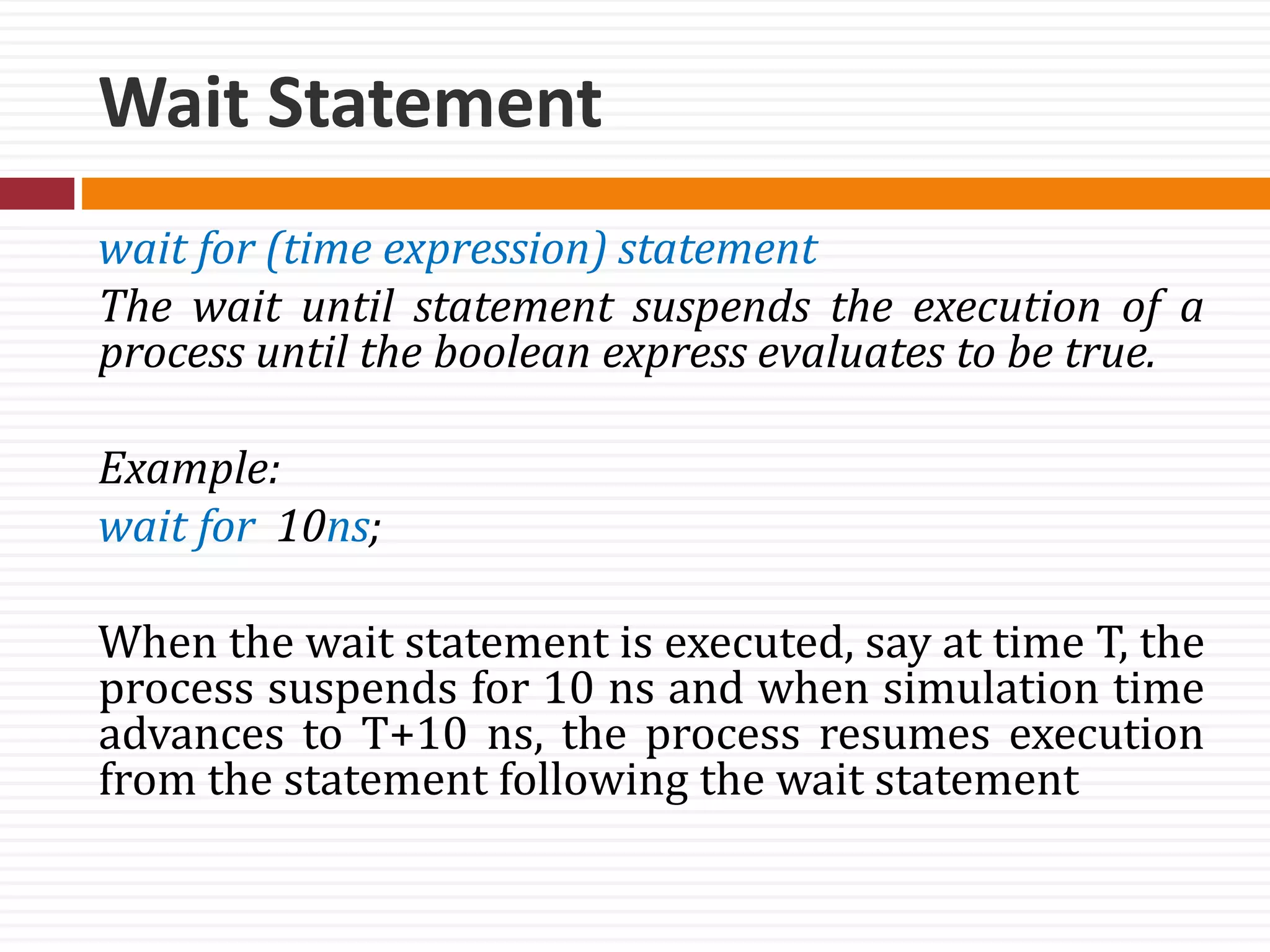
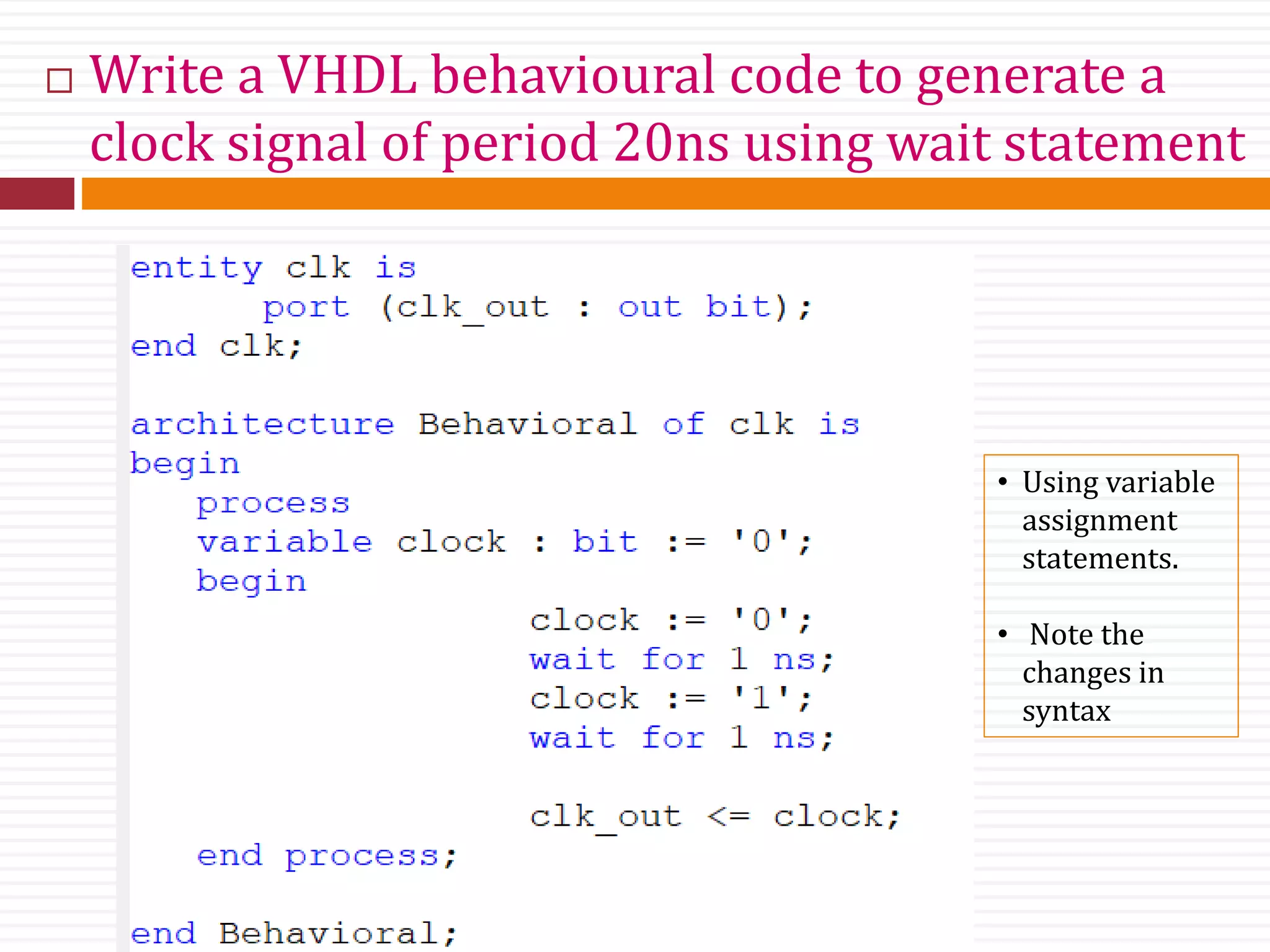
wait-statement,
if-statement,
case-statement,
loop-statement,
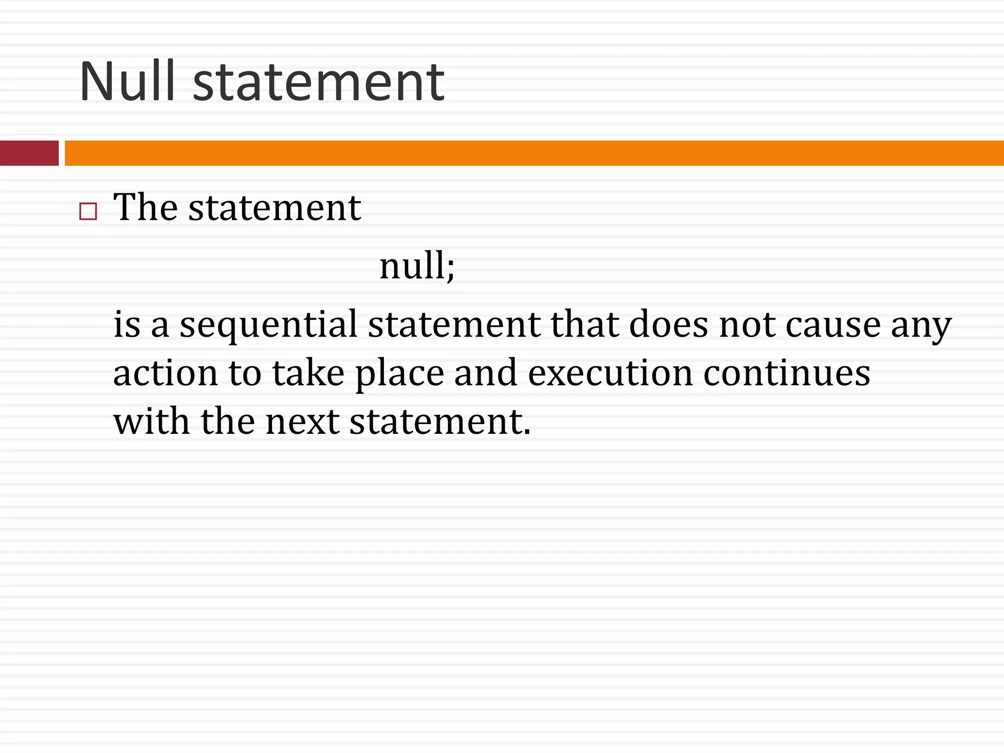
null-statement,
exit-statement,
next-statement,
assertion-statement,
procedure-call-statement,
return-statement.](https://image.slidesharecdn.com/vdlec5and6-171209180428/75/VHDL-Behavioral-Description-3-2048.jpg)
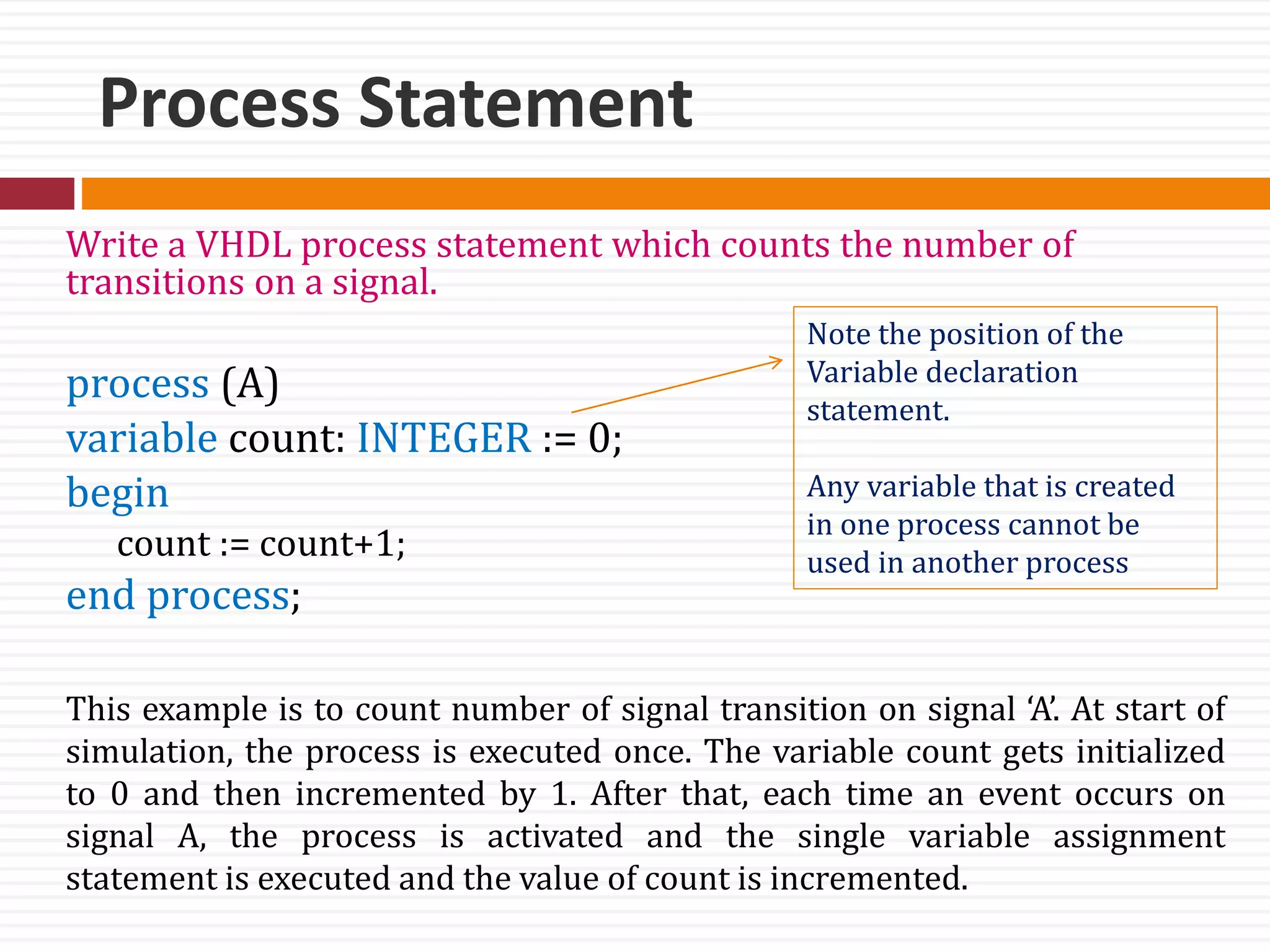
![Variable Assignment Statement
Variables can be declared and used inside a process statement.
Syntax for variable declaration:
variable [variable_Identifier] : [type] := [optional_initial_value]
Example: variable count : integer := 0;
Syntax for variable assignment:
variable-object := expression;
Example: Count := count + 1;
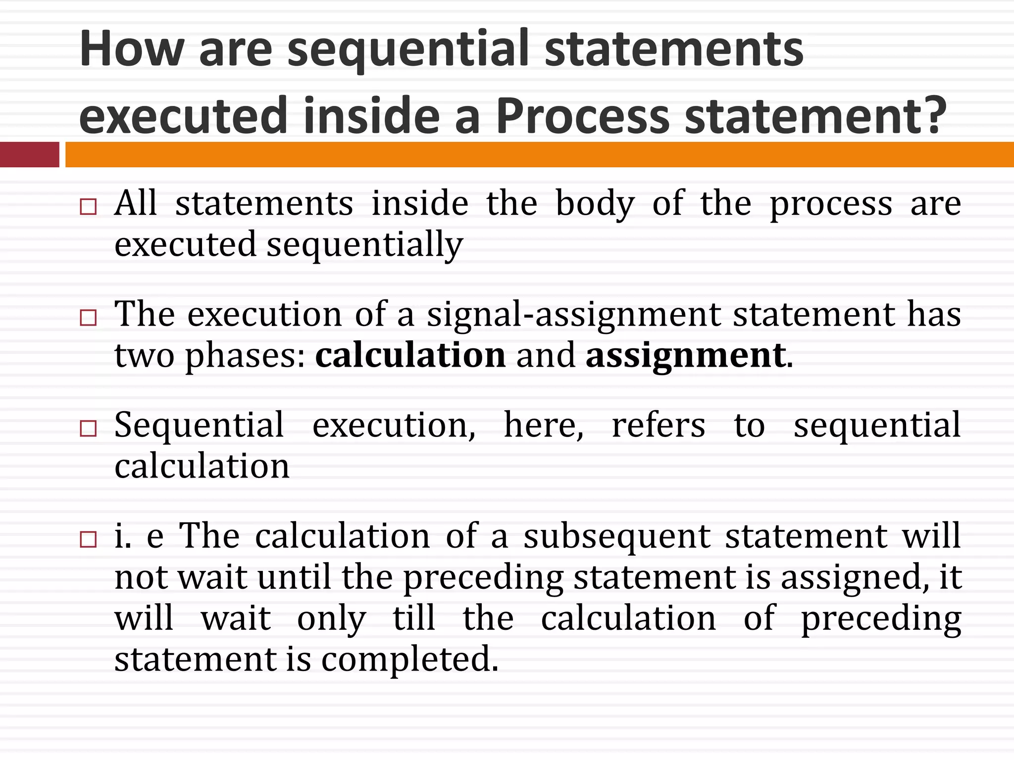
The expression is evaluated when the statement is executed and
the computed value is assigned to the variable object
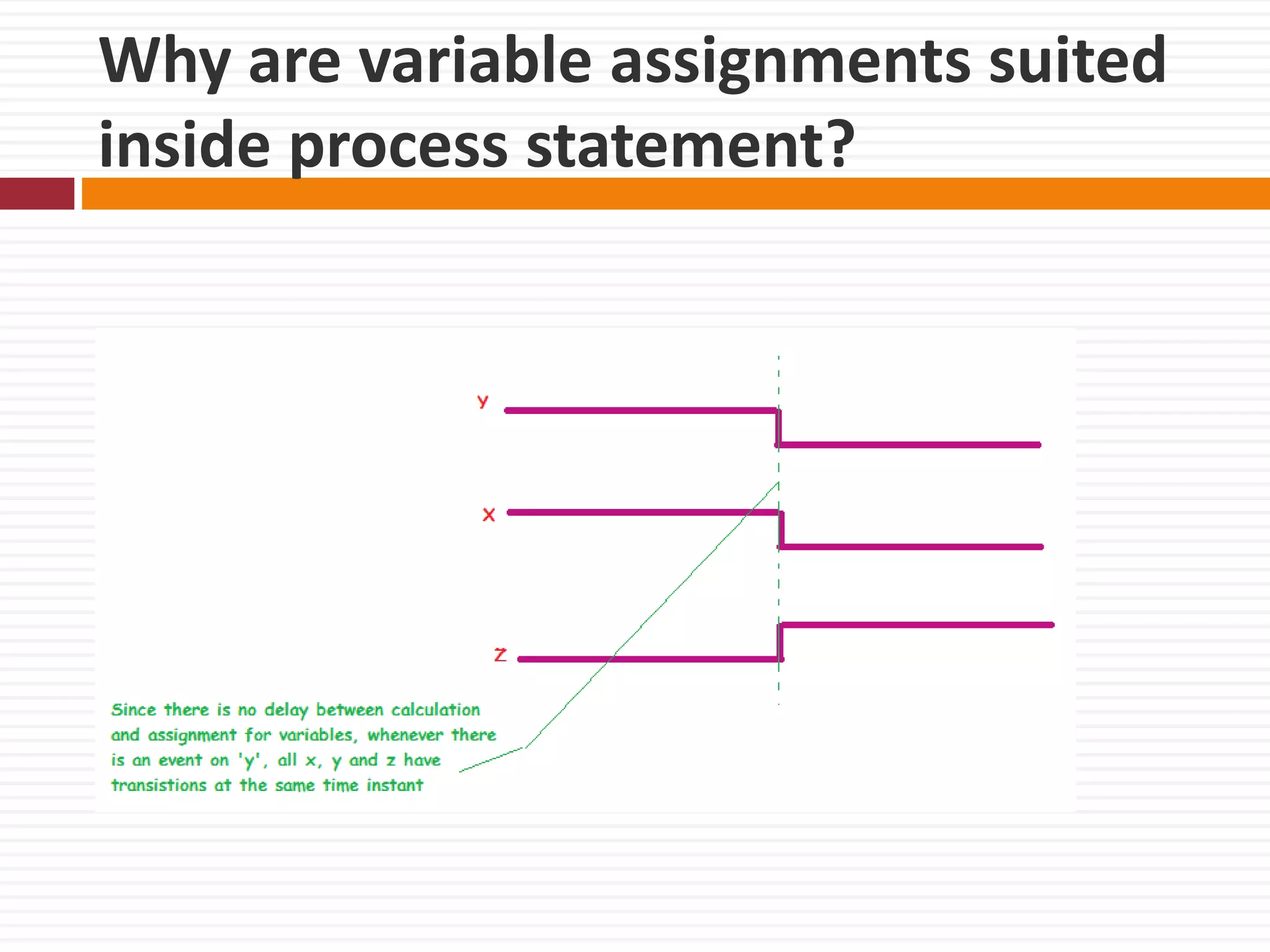
instantaneously, that is, at the current simulation time](https://image.slidesharecdn.com/vdlec5and6-171209180428/75/VHDL-Behavioral-Description-14-2048.jpg)


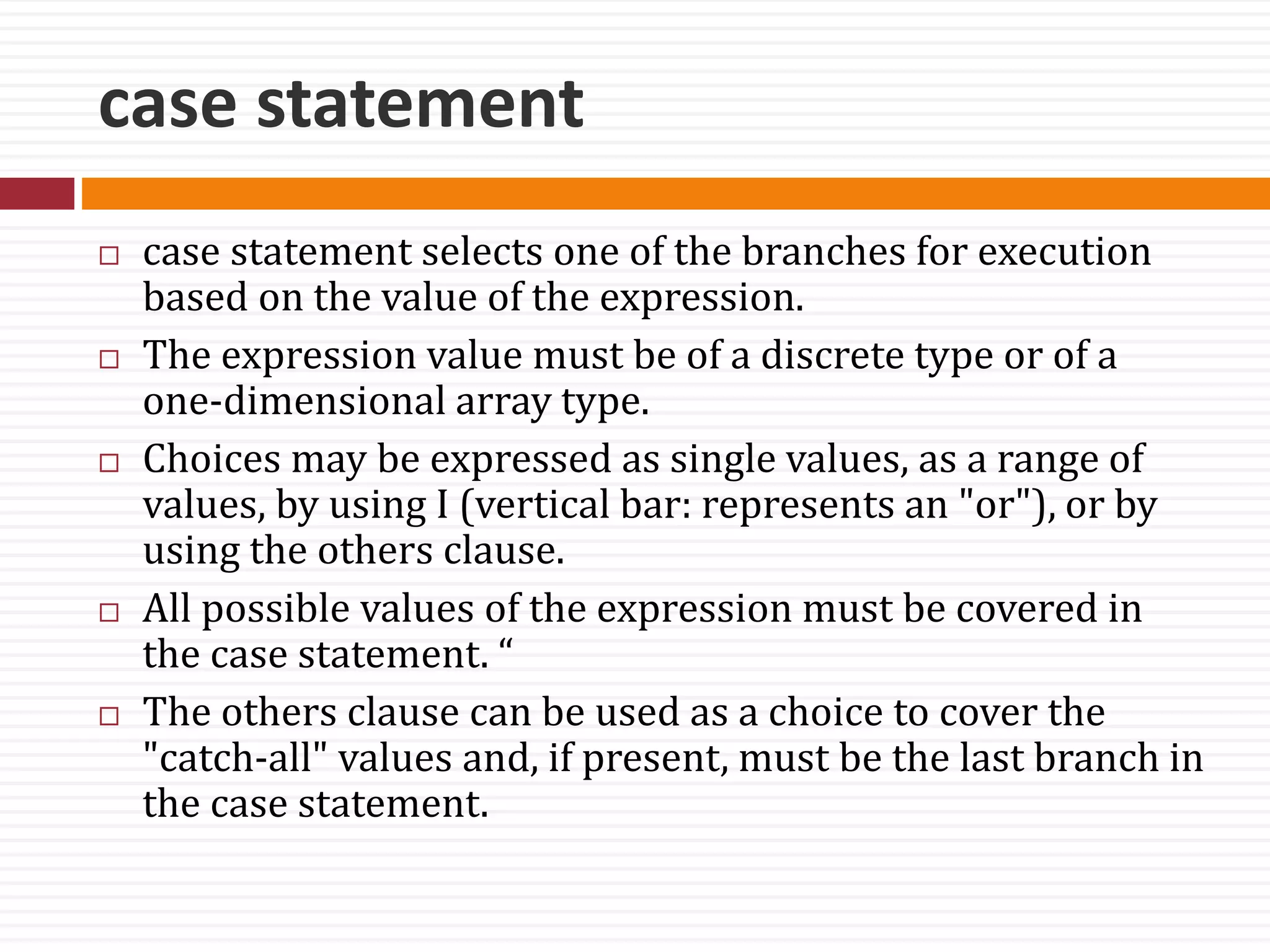
![case statement
Syntax:
case expression is
when choices => sequential-statements -- branch #1
when choices => sequential-statements -- branch #2
-- Can have any number of branches.
[ when others => sequential-statements ] -- last branch
end case;](https://image.slidesharecdn.com/vdlec5and6-171209180428/75/VHDL-Behavioral-Description-42-2048.jpg)


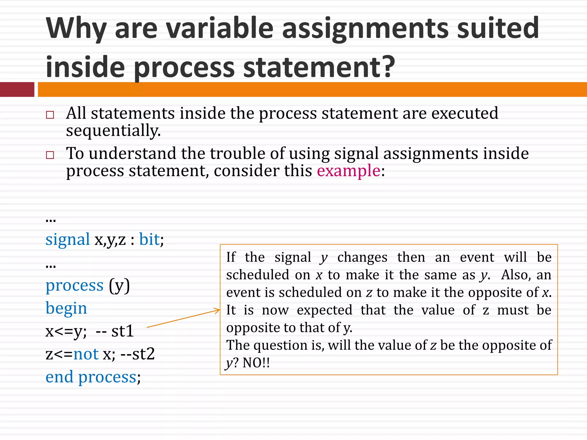
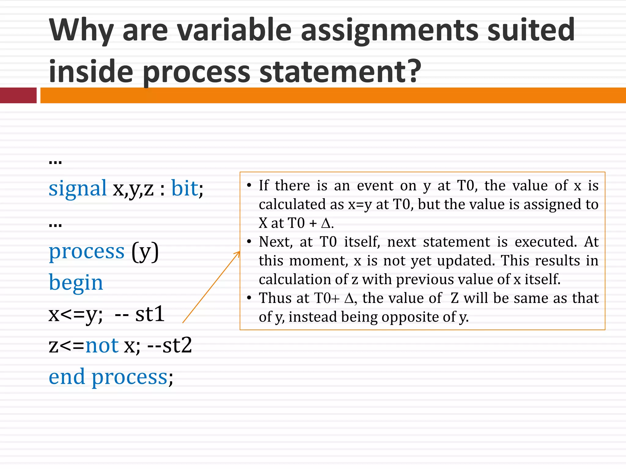
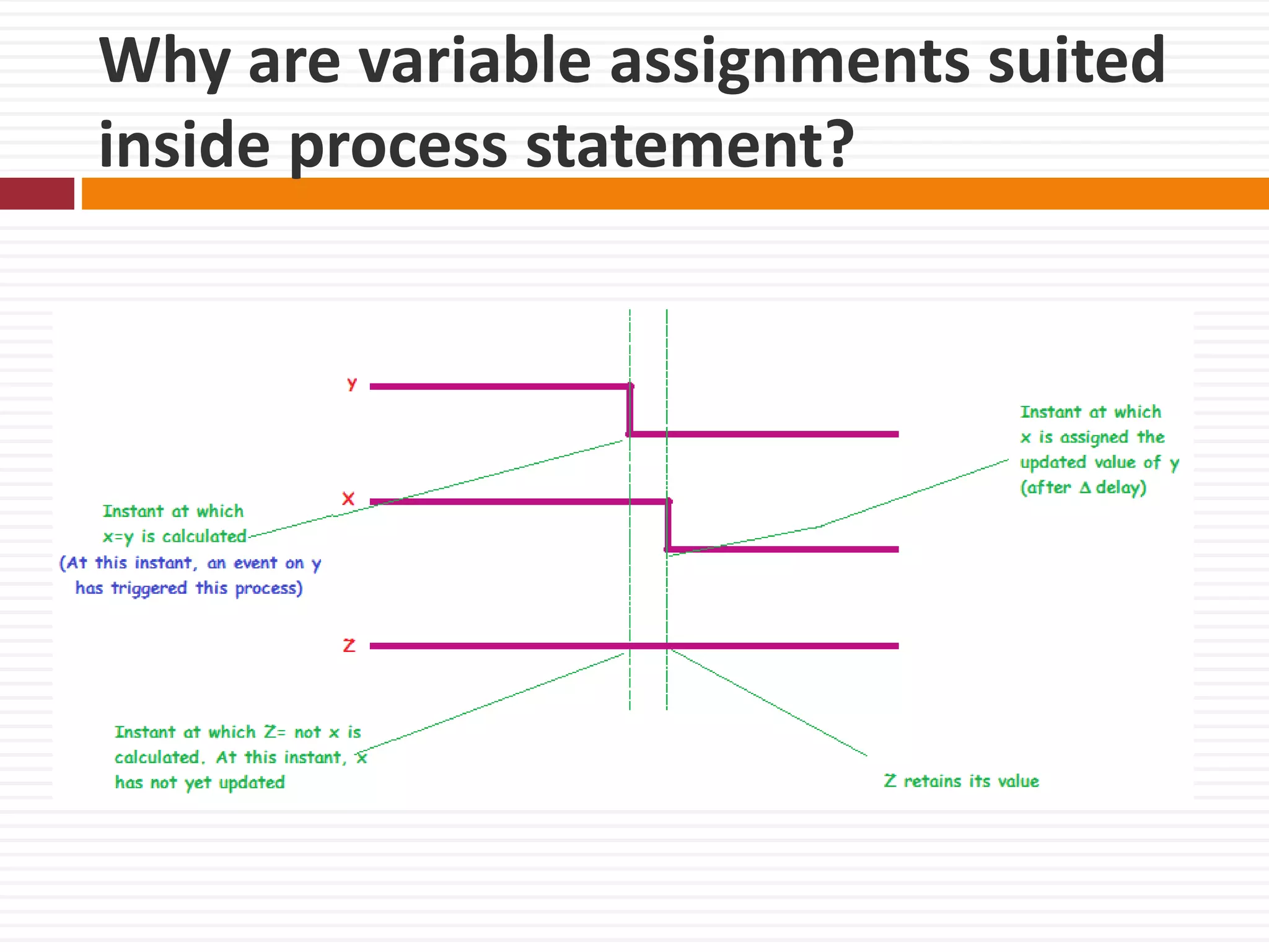
The document discusses VHDL behavioral description focusing on processes, which describe how outputs behave with changing inputs without needing to know the internal logic structure. It covers the syntax, activation via sensitivity lists, and the differences between variable and signal assignments in sequential statements, alongside examples and explanations of wait and if statements. It also highlights the implications of using processes without sensitivity lists and the mechanics of signal assignments in VHDL.