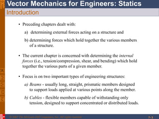
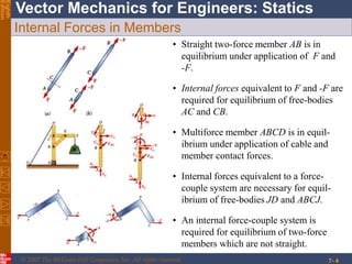
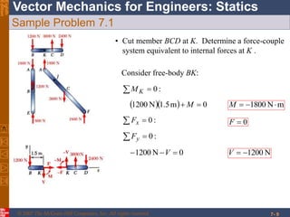
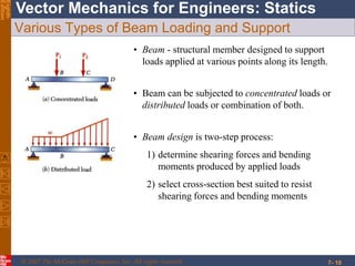
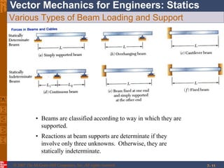
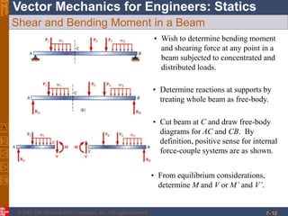
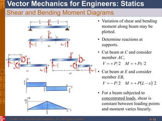
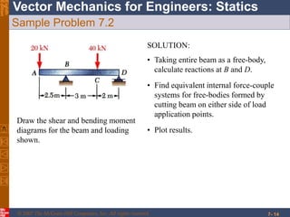
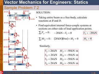
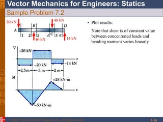
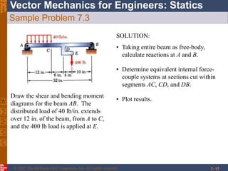
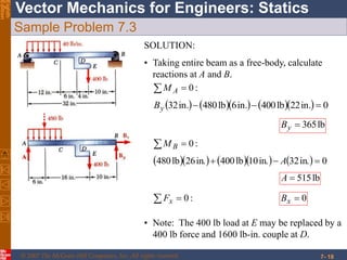
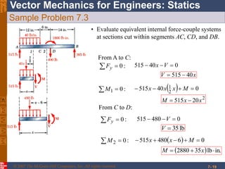
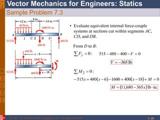
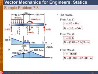
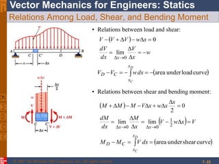
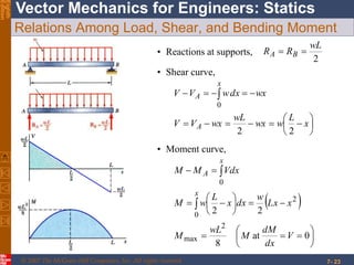
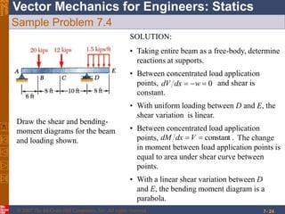
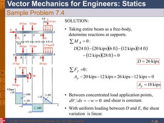
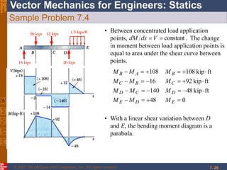
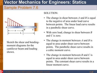
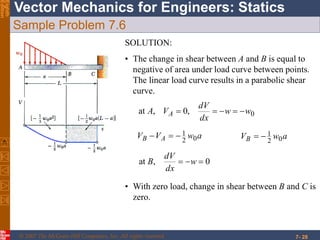
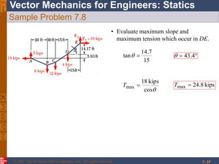
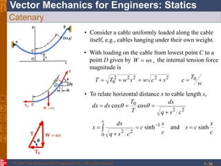
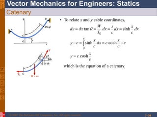
VECTOR MECHANICS FOR ENGINEERS:
STATICS
Eighth Edition
Ferdinand P. Beer
E. Russell Johnston, Jr.
Lecture Notes:
J. Walt Oler
Texas Tech University
CHAPTER
© 2007 The McGraw-Hill Companies, Inc. All rights reserved.
7 Forces in Beams and Cables
© 2007 The McGraw-Hill Companies, Inc. All rights reserved.
Vector Mechanics for Engineers: StaticsEighth
Edition
7- 2
Contents
Introduction
Internal Forces in Members
Sample Problem 7.1
Various Types of Beam Loading and
Support
Shear and Bending Moment in a
Beam
Sample Problem 7.2
Sample Problem 7.3
Relations Among Load, Shear, and
Bending Moment
Sample Problem 7.4
Sample Problem 7.6
Cables With Concentrated Loads
Cables With Distributed Loads
Parabolic Cable
Sample Problem 7.8
Catenary
© 2007 The McGraw-Hill Companies, Inc. All rights reserved.
Vector Mechanics for Engineers: StaticsEighth
Edition
7- 3
Introduction
• Preceding chapters dealt with:
a) determining external forces acting on a structure and
b) determining forces which hold together the various members
of a structure.
• The current chapter is concerned with determining the internal
forces (i.e., tension/compression, shear, and bending) which hold
together the various parts of a given member.
• Focus is on two important types of engineering structures:
a) Beams - usually long, straight, prismatic members designed
to support loads applied at various points along the member.
b) Cables - flexible members capable of withstanding only
tension, designed to support concentrated or distributed loads.
© 2007 The McGraw-Hill Companies, Inc. All rights reserved.
Vector Mechanics for Engineers: StaticsEighth
Edition
7- 4
Internal Forces in Members
• Straight two-force member AB is in
equilibrium under application of F and
-F.
• Internal forces equivalent to F and -F are
required for equilibrium of free-bodies
AC and CB.
• Multiforce member ABCD is in equil-
ibrium under application of cable and
member contact forces.
• Internal forces equivalent to a force-
couple system are necessary for equil-
ibrium of free-bodies JD and ABCJ.
• An internal force-couple system is
required for equilibrium of two-force
members which are not straight.
© 2007 The McGraw-Hill Companies, Inc. All rights reserved.
Vector Mechanics for Engineers: StaticsEighth
Edition
7- 5
Sample Problem 7.1
Determine the internal forces (a) in
member ACF at point J and (b) in
member BCD at K.
SOLUTION:
• Compute reactions and forces at
connections for each member.
• Cut member ACF at J. The internal
forces at J are represented by equivalent
force-couple system which is determined
by considering equilibrium of either part.
• Cut member BCD at K. Determine
force-couple system equivalent to
internal forces at K by applying
equilibrium conditions to either part.
© 2007 The McGraw-Hill Companies, Inc. All rights reserved.
Vector Mechanics for Engineers: StaticsEighth
Edition
7- 6
Sample Problem 7.1
:0 yF
0N1800N2400  yE NEy 600
:0 xF 0xE
SOLUTION:
• Compute reactions and connection forces.
:0 EM
     0m8.4m6.3N2400  F N1800F
Consider entire frame as a free-body:
© 2007 The McGraw-Hill Companies, Inc. All rights reserved.
Vector Mechanics for Engineers: StaticsEighth
Edition
7- 7
Sample Problem 7.1
Consider member BCD as free-body:
:0 BM
     0m4.2m6.3N2400  yC N3600yC
:0 CM
     0m4.2m2.1N2400  yB N1200yB
:0 xF 0 xx CB
Consider member ABE as free-body:
:0 AM   0m4.2 xB 0xB
  :0xF 0 xx AB 0xA
  :0yF 0N600  yy BA N1800yA
From member BCD,
:0 xF 0 xx CB 0xC
© 2007 The McGraw-Hill Companies, Inc. All rights reserved.
Vector Mechanics for Engineers: StaticsEighth
Edition
7- 8
Sample Problem 7.1
• Cut member ACF at J. The internal forces at J are
represented by equivalent force-couple system.
Consider free-body AJ:
:0 JM
   0m2.1N1800  M mN2160 M
:0 xF
  07.41cosN1800 F N1344F
:0 yF
  07.41sinN1800 V N1197V
© 2007 The McGraw-Hill Companies, Inc. All rights reserved.
Vector Mechanics for Engineers: StaticsEighth
Edition
7- 9
Sample Problem 7.1
• Cut member BCD at K. Determine a force-couple
system equivalent to internal forces at K .
Consider free-body BK:
:0 KM
   0m5.1N1200  M mN1800 M
:0 xF 0F
:0 yF
0N1200  V N1200V
© 2007 The McGraw-Hill Companies, Inc. All rights reserved.
Vector Mechanics for Engineers: StaticsEighth
Edition
7- 10
Various Types of Beam Loading and Support
• Beam - structural member designed to support
loads applied at various points along its length.
• Beam design is two-step process:
1) determine shearing forces and bending
moments produced by applied loads
2) select cross-section best suited to resist
shearing forces and bending moments
• Beam can be subjected to concentrated loads or
distributed loads or combination of both.
© 2007 The McGraw-Hill Companies, Inc. All rights reserved.
Vector Mechanics for Engineers: StaticsEighth
Edition
7- 11
Various Types of Beam Loading and Support
• Beams are classified according to way in which they are
supported.
• Reactions at beam supports are determinate if they
involve only three unknowns. Otherwise, they are
statically indeterminate.
© 2007 The McGraw-Hill Companies, Inc. All rights reserved.
Vector Mechanics for Engineers: StaticsEighth
Edition
7- 12
Shear and Bending Moment in a Beam
• Wish to determine bending moment
and shearing force at any point in a
beam subjected to concentrated and
distributed loads.
• Determine reactions at supports by
treating whole beam as free-body.
• Cut beam at C and draw free-body
diagrams for AC and CB. By
definition, positive sense for internal
force-couple systems are as shown.
• From equilibrium considerations,
determine M and V or M’ and V’.
© 2007 The McGraw-Hill Companies, Inc. All rights reserved.
Vector Mechanics for Engineers: StaticsEighth
Edition
7- 13
Shear and Bending Moment Diagrams
• Variation of shear and bending
moment along beam may be
plotted.
• Determine reactions at
supports.
• Cut beam at C and consider
member AC,
22 PxMPV 
• Cut beam at E and consider
member EB,
  22 xLPMPV 
• For a beam subjected to
concentrated loads, shear is
constant between loading points
and moment varies linearly.
© 2007 The McGraw-Hill Companies, Inc. All rights reserved.
Vector Mechanics for Engineers: StaticsEighth
Edition
7- 14
Sample Problem 7.2
Draw the shear and bending moment
diagrams for the beam and loading
shown.
SOLUTION:
• Taking entire beam as a free-body,
calculate reactions at B and D.
• Find equivalent internal force-couple
systems for free-bodies formed by
cutting beam on either side of load
application points.
• Plot results.
© 2007 The McGraw-Hill Companies, Inc. All rights reserved.
Vector Mechanics for Engineers: StaticsEighth
Edition
7- 15
Sample Problem 7.2
SOLUTION:
• Taking entire beam as a free-body, calculate
reactions at B and D.
• Find equivalent internal force-couple systems at
sections on either side of load application points.
  :0yF 0kN20 1  V kN201 V
:02 M    0m0kN20 1  M 01 M
mkN50kN26
mkN50kN26
mkN50kN26
mkN50kN26
66
55
44
33




MV
MV
MV
MV
Similarly,
© 2007 The McGraw-Hill Companies, Inc. All rights reserved.
Vector Mechanics for Engineers: StaticsEighth
Edition
7- 16
Sample Problem 7.2
• Plot results.
Note that shear is of constant value
between concentrated loads and
bending moment varies linearly.
© 2007 The McGraw-Hill Companies, Inc. All rights reserved.
Vector Mechanics for Engineers: StaticsEighth
Edition
7- 17
Sample Problem 7.3
Draw the shear and bending moment
diagrams for the beam AB. The
distributed load of 40 lb/in. extends
over 12 in. of the beam, from A to C,
and the 400 lb load is applied at E.
SOLUTION:
• Taking entire beam as free-body,
calculate reactions at A and B.
• Determine equivalent internal force-
couple systems at sections cut within
segments AC, CD, and DB.
• Plot results.
© 2007 The McGraw-Hill Companies, Inc. All rights reserved.
Vector Mechanics for Engineers: StaticsEighth
Edition
7- 18
Sample Problem 7.3
SOLUTION:
• Taking entire beam as a free-body, calculate
reactions at A and B.
:0 AM
        0in.22lb400in.6lb480in.32 yB
lb365yB
:0 BM
        0in.32in.10lb400in.26lb480  A
lb515A
:0 xF 0xB
• Note: The 400 lb load at E may be replaced by a
400 lb force and 1600 lb-in. couple at D.
© 2007 The McGraw-Hill Companies, Inc. All rights reserved.
Vector Mechanics for Engineers: StaticsEighth
Edition
7- 19
Sample Problem 7.3
:01 M   040515 2
1  Mxxx
2
20515 xxM 
:02 M   06480515  Mxx
  in.lb352880  xM
From C to D:
  :0yF 0480515  V
lb35V
• Evaluate equivalent internal force-couple systems
at sections cut within segments AC, CD, and DB.
From A to C:
  :0yF 040515  Vx
xV 40515 
© 2007 The McGraw-Hill Companies, Inc. All rights reserved.
Vector Mechanics for Engineers: StaticsEighth
Edition
7- 20
Sample Problem 7.3
:02 M
    01840016006480515  Mxxx
  in.lb365680,11  xM
• Evaluate equivalent internal force-couple
systems at sections cut within segments AC,
CD, and DB.
From D to B:
  :0yF 0400480515  V
lb365V
© 2007 The McGraw-Hill Companies, Inc. All rights reserved.
Vector Mechanics for Engineers: StaticsEighth
Edition
7- 21
Sample Problem 7.3
• Plot results.
From A to C:
xV 40515 
2
20515 xxM 
From C to D:
lb35V
  in.lb352880  xM
From D to B:
lb365V
  in.lb365680,11  xM
© 2007 The McGraw-Hill Companies, Inc. All rights reserved.
Vector Mechanics for Engineers: StaticsEighth
Edition
7- 22
Relations Among Load, Shear, and Bending Moment
• Relations between load and shear:
 
w
x
V
dx
dV
xwVVV
x





 0
lim
0
 curveloadunderarea 
D
C
x
x
CD dxwVV
• Relations between shear and bending moment:
 
  VxwV
x
M
dx
dM
x
xwxVMMM
xx







 2
1
00
limlim
0
2
 curveshearunderarea 
D
C
x
x
CD dxVMM
© 2007 The McGraw-Hill Companies, Inc. All rights reserved.
Vector Mechanics for Engineers: StaticsEighth
Edition
7- 23
Relations Among Load, Shear, and Bending Moment
• Reactions at supports,
2
wL
RR BA 
• Shear curve,







 
x
L
wwx
wL
wxVV
wxdxwVV
A
x
A
22
0
• Moment curve,
 

















0at
8
22
2
max
2
0
0
V
dx
dM
M
wL
M
xxL
w
dxx
L
wM
VdxMM
x
x
A
© 2007 The McGraw-Hill Companies, Inc. All rights reserved.
Vector Mechanics for Engineers: StaticsEighth
Edition
7- 24
Sample Problem 7.4
Draw the shear and bending-
moment diagrams for the beam
and loading shown.
SOLUTION:
• Taking entire beam as a free-body, determine
reactions at supports.
• With uniform loading between D and E, the
shear variation is linear.
• Between concentrated load application
points, and shear is
constant.
0 wdxdV
• Between concentrated load application
points, The change
in moment between load application points is
equal to area under shear curve between
points.
.constantVdxdM
• With a linear shear variation between D
and E, the bending moment diagram is a
parabola.
© 2007 The McGraw-Hill Companies, Inc. All rights reserved.
Vector Mechanics for Engineers: StaticsEighth
Edition
7- 25
Sample Problem 7.4
• Between concentrated load application points,
and shear is constant.0 wdxdV
• With uniform loading between D and E, the shear
variation is linear.
SOLUTION:
• Taking entire beam as a free-body,
determine reactions at supports.
  :0AM
       
   0ft82kips12
ft14kips12ft6kips20ft24

D
kips26D
:0 yF
0kips12kips26kips12kips20 yA
kips18yA
© 2007 The McGraw-Hill Companies, Inc. All rights reserved.
Vector Mechanics for Engineers: StaticsEighth
Edition
7- 26
Sample Problem 7.4
• Between concentrated load application
points, The change
in moment between load application points is
equal to area under the shear curve between
points.
.constantVdxdM
• With a linear shear variation between D
and E, the bending moment diagram is a
parabola.
048
ftkip48140
ftkip9216
ftkip108108




EDE
DCD
CBC
BAB
MMM
MMM
MMM
MMM
© 2007 The McGraw-Hill Companies, Inc. All rights reserved.
Vector Mechanics for Engineers: StaticsEighth
Edition
7- 27
Sample Problem 7.6
Sketch the shear and bending-
moment diagrams for the
cantilever beam and loading
shown.
SOLUTION:
• The change in shear between A and B is equal
to the negative of area under load curve
between points. The linear load curve results
in a parabolic shear curve.
• With zero load, change in shear between B
and C is zero.
• The change in moment between A and B is
equal to area under shear curve between
points. The parabolic shear curve results in
a cubic moment curve.
• The change in moment between B and C is
equal to area under shear curve between
points. The constant shear curve results in a
linear moment curve.
© 2007 The McGraw-Hill Companies, Inc. All rights reserved.
Vector Mechanics for Engineers: StaticsEighth
Edition
7- 28
Sample Problem 7.6
• With zero load, change in shear between B and C is
zero.
SOLUTION:
• The change in shear between A and B is equal to
negative of area under load curve between points.
The linear load curve results in a parabolic shear
curve.
awVV AB 02
1 awVB 02
1
0,at  w
dx
dV
B
0,0,at ww
dx
dV
VA A 
© 2007 The McGraw-Hill Companies, Inc. All rights reserved.
Vector Mechanics for Engineers: StaticsEighth
Edition
7- 29
Sample Problem 7.6
• The change in moment between A and B is equal
to area under shear curve between the points.
The parabolic shear curve results in a cubic
moment curve.
• The change in moment between B and C is equal
to area under shear curve between points. The
constant shear curve results in a linear moment
curve.
   aLawMaLawMM
awMawMM
CBC
BAB


306
1
02
1
2
03
12
03
1
0,0,at  V
dx
dM
MA A
© 2007 The McGraw-Hill Companies, Inc. All rights reserved.
Vector Mechanics for Engineers: StaticsEighth
Edition
7- 30
Cables With Concentrated Loads
• Cables are applied as structural elements
in suspension bridges, transmission lines,
aerial tramways, guy wires for high
towers, etc.
• For analysis, assume:
a) concentrated vertical loads on given
vertical lines,
b) weight of cable is negligible,
c) cable is flexible, i.e., resistance to
bending is small,
d) portions of cable between successive
loads may be treated as two force
members
• Wish to determine shape of cable, i.e.,
vertical distance from support A to each
load point.
© 2007 The McGraw-Hill Companies, Inc. All rights reserved.
Vector Mechanics for Engineers: StaticsEighth
Edition
7- 31
Cables With Concentrated Loads
• Consider entire cable as free-body. Slopes of
cable at A and B are not known - two reaction
components required at each support.
• Four unknowns are involved and three
equations of equilibrium are not sufficient to
determine the reactions.
• For other points on cable,
2yields02
yMC 
yxyx TTFF ,yield0,0  
• constantcos  xx ATT 
• Additional equation is obtained by
considering equilibrium of portion of cable
AD and assuming that coordinates of point D
on the cable are known. The additional
equation is .0 DM
© 2007 The McGraw-Hill Companies, Inc. All rights reserved.
Vector Mechanics for Engineers: StaticsEighth
Edition
7- 32
Cables With Distributed Loads
• For cable carrying a distributed load:
a) cable hangs in shape of a curve
b) internal force is a tension force directed along
tangent to curve.
• Consider free-body for portion of cable extending
from lowest point C to given point D. Forces are
horizontal force T0 at C and tangential force T at D.
• From force triangle:
0
22
0
0
tan
sincos
T
W
WTT
WTTT




• Horizontal component of T is uniform over cable.
• Vertical component of T is equal to magnitude of W
measured from lowest point.
• Tension is minimum at lowest point and maximum
at A and B.
© 2007 The McGraw-Hill Companies, Inc. All rights reserved.
Vector Mechanics for Engineers: StaticsEighth
Edition
7- 33
Parabolic Cable
• Consider a cable supporting a uniform, horizontally
distributed load, e.g., support cables for a
suspension bridge.
• With loading on cable from lowest point C to a
point D given by internal tension force
magnitude and direction are
,wxW 
0
222
0 tan
T
wx
xwTT  
• Summing moments about D,
0
2
:0 0  yT
x
wxM D
0
2
2T
wx
y 
or
The cable forms a parabolic curve.
© 2007 The McGraw-Hill Companies, Inc. All rights reserved.
Vector Mechanics for Engineers: StaticsEighth
Edition
7- 34
Sample Problem 7.8
The cable AE supports three vertical
loads from the points indicated. If
point C is 5 ft below the left support,
determine (a) the elevation of points
B and D, and (b) the maximum slope
and maximum tension in the cable.
SOLUTION:
• Determine reaction force components at
A from solution of two equations formed
from taking entire cable as free-body
and summing moments about E, and
from taking cable portion ABC as a free-
body and summing moments about C.
• Calculate elevation of B by considering
AB as a free-body and summing
moments B. Similarly, calculate
elevation of D using ABCD as a free-
body.
• Evaluate maximum slope and
maximum tension which occur in DE.
© 2007 The McGraw-Hill Companies, Inc. All rights reserved.
Vector Mechanics for Engineers: StaticsEighth
Edition
7- 35
Sample Problem 7.8
SOLUTION:
• Determine two reaction force components at A
from solution of two equations formed from
taking entire cable as a free-body and summing
moments about E,
     
06606020
041512306406020
:0



yx
yx
E
AA
AA
M
and from taking cable portion ABC as a
free-body and summing moments about C.
  0610305
:0


yx
C
AA
M
Solving simultaneously,
kips5kips18  yx AA
© 2007 The McGraw-Hill Companies, Inc. All rights reserved.
Vector Mechanics for Engineers: StaticsEighth
Edition
7- 36
Sample Problem 7.8
• Calculate elevation of B by considering AB as
a free-body and summing moments B.
    020518:0  BB yM
ft56.5By
Similarly, calculate elevation of D using
ABCD as a free-body.
        0121562554518
:0


Dy
M
ft83.5Dy
© 2007 The McGraw-Hill Companies, Inc. All rights reserved.
Vector Mechanics for Engineers: StaticsEighth
Edition
7- 37
Sample Problem 7.8
• Evaluate maximum slope and
maximum tension which occur in DE.
15
7.14
tan   4.43
cos
kips18
max T kips8.24max T
© 2007 The McGraw-Hill Companies, Inc. All rights reserved.
Vector Mechanics for Engineers: StaticsEighth
Edition
7- 38
Catenary
• Consider a cable uniformly loaded along the cable
itself, e.g., cables hanging under their own weight.
• With loading on the cable from lowest point C to a
point D given by the internal tension force
magnitude is
w
T
cscwswTT 022222
0 
,wsW 
• To relate horizontal distance x to cable length s,
c
x
cs
c
s
c
csq
ds
x
csq
ds
T
T
dsdx
s
sinhandsinh
coscos
1
0
22
22
0








© 2007 The McGraw-Hill Companies, Inc. All rights reserved.
Vector Mechanics for Engineers: StaticsEighth
Edition
7- 39
Catenary
• To relate x and y cable coordinates,
c
x
cy
c
c
x
cdx
c
x
cy
dx
c
x
dx
c
s
dx
T
W
dxdy
x
cosh
coshsinh
sinhtan
0
0





which is the equation of a catenary.

Loads on beam

  • 1.
    VECTOR MECHANICS FORENGINEERS: STATICS Eighth Edition Ferdinand P. Beer E. Russell Johnston, Jr. Lecture Notes: J. Walt Oler Texas Tech University CHAPTER © 2007 The McGraw-Hill Companies, Inc. All rights reserved. 7 Forces in Beams and Cables
  • 2.
    © 2007 TheMcGraw-Hill Companies, Inc. All rights reserved. Vector Mechanics for Engineers: StaticsEighth Edition 7- 2 Contents Introduction Internal Forces in Members Sample Problem 7.1 Various Types of Beam Loading and Support Shear and Bending Moment in a Beam Sample Problem 7.2 Sample Problem 7.3 Relations Among Load, Shear, and Bending Moment Sample Problem 7.4 Sample Problem 7.6 Cables With Concentrated Loads Cables With Distributed Loads Parabolic Cable Sample Problem 7.8 Catenary
  • 3.
    © 2007 TheMcGraw-Hill Companies, Inc. All rights reserved. Vector Mechanics for Engineers: StaticsEighth Edition 7- 3 Introduction • Preceding chapters dealt with: a) determining external forces acting on a structure and b) determining forces which hold together the various members of a structure. • The current chapter is concerned with determining the internal forces (i.e., tension/compression, shear, and bending) which hold together the various parts of a given member. • Focus is on two important types of engineering structures: a) Beams - usually long, straight, prismatic members designed to support loads applied at various points along the member. b) Cables - flexible members capable of withstanding only tension, designed to support concentrated or distributed loads.
  • 4.
    © 2007 TheMcGraw-Hill Companies, Inc. All rights reserved. Vector Mechanics for Engineers: StaticsEighth Edition 7- 4 Internal Forces in Members • Straight two-force member AB is in equilibrium under application of F and -F. • Internal forces equivalent to F and -F are required for equilibrium of free-bodies AC and CB. • Multiforce member ABCD is in equil- ibrium under application of cable and member contact forces. • Internal forces equivalent to a force- couple system are necessary for equil- ibrium of free-bodies JD and ABCJ. • An internal force-couple system is required for equilibrium of two-force members which are not straight.
  • 5.
    © 2007 TheMcGraw-Hill Companies, Inc. All rights reserved. Vector Mechanics for Engineers: StaticsEighth Edition 7- 5 Sample Problem 7.1 Determine the internal forces (a) in member ACF at point J and (b) in member BCD at K. SOLUTION: • Compute reactions and forces at connections for each member. • Cut member ACF at J. The internal forces at J are represented by equivalent force-couple system which is determined by considering equilibrium of either part. • Cut member BCD at K. Determine force-couple system equivalent to internal forces at K by applying equilibrium conditions to either part.
  • 6.
    © 2007 TheMcGraw-Hill Companies, Inc. All rights reserved. Vector Mechanics for Engineers: StaticsEighth Edition 7- 6 Sample Problem 7.1 :0 yF 0N1800N2400  yE NEy 600 :0 xF 0xE SOLUTION: • Compute reactions and connection forces. :0 EM      0m8.4m6.3N2400  F N1800F Consider entire frame as a free-body:
  • 7.
    © 2007 TheMcGraw-Hill Companies, Inc. All rights reserved. Vector Mechanics for Engineers: StaticsEighth Edition 7- 7 Sample Problem 7.1 Consider member BCD as free-body: :0 BM      0m4.2m6.3N2400  yC N3600yC :0 CM      0m4.2m2.1N2400  yB N1200yB :0 xF 0 xx CB Consider member ABE as free-body: :0 AM   0m4.2 xB 0xB   :0xF 0 xx AB 0xA   :0yF 0N600  yy BA N1800yA From member BCD, :0 xF 0 xx CB 0xC
  • 8.
    © 2007 TheMcGraw-Hill Companies, Inc. All rights reserved. Vector Mechanics for Engineers: StaticsEighth Edition 7- 8 Sample Problem 7.1 • Cut member ACF at J. The internal forces at J are represented by equivalent force-couple system. Consider free-body AJ: :0 JM    0m2.1N1800  M mN2160 M :0 xF   07.41cosN1800 F N1344F :0 yF   07.41sinN1800 V N1197V
  • 9.
    © 2007 TheMcGraw-Hill Companies, Inc. All rights reserved. Vector Mechanics for Engineers: StaticsEighth Edition 7- 9 Sample Problem 7.1 • Cut member BCD at K. Determine a force-couple system equivalent to internal forces at K . Consider free-body BK: :0 KM    0m5.1N1200  M mN1800 M :0 xF 0F :0 yF 0N1200  V N1200V
  • 10.
    © 2007 TheMcGraw-Hill Companies, Inc. All rights reserved. Vector Mechanics for Engineers: StaticsEighth Edition 7- 10 Various Types of Beam Loading and Support • Beam - structural member designed to support loads applied at various points along its length. • Beam design is two-step process: 1) determine shearing forces and bending moments produced by applied loads 2) select cross-section best suited to resist shearing forces and bending moments • Beam can be subjected to concentrated loads or distributed loads or combination of both.
  • 11.
    © 2007 TheMcGraw-Hill Companies, Inc. All rights reserved. Vector Mechanics for Engineers: StaticsEighth Edition 7- 11 Various Types of Beam Loading and Support • Beams are classified according to way in which they are supported. • Reactions at beam supports are determinate if they involve only three unknowns. Otherwise, they are statically indeterminate.
  • 12.
    © 2007 TheMcGraw-Hill Companies, Inc. All rights reserved. Vector Mechanics for Engineers: StaticsEighth Edition 7- 12 Shear and Bending Moment in a Beam • Wish to determine bending moment and shearing force at any point in a beam subjected to concentrated and distributed loads. • Determine reactions at supports by treating whole beam as free-body. • Cut beam at C and draw free-body diagrams for AC and CB. By definition, positive sense for internal force-couple systems are as shown. • From equilibrium considerations, determine M and V or M’ and V’.
  • 13.
    © 2007 TheMcGraw-Hill Companies, Inc. All rights reserved. Vector Mechanics for Engineers: StaticsEighth Edition 7- 13 Shear and Bending Moment Diagrams • Variation of shear and bending moment along beam may be plotted. • Determine reactions at supports. • Cut beam at C and consider member AC, 22 PxMPV  • Cut beam at E and consider member EB,   22 xLPMPV  • For a beam subjected to concentrated loads, shear is constant between loading points and moment varies linearly.
  • 14.
    © 2007 TheMcGraw-Hill Companies, Inc. All rights reserved. Vector Mechanics for Engineers: StaticsEighth Edition 7- 14 Sample Problem 7.2 Draw the shear and bending moment diagrams for the beam and loading shown. SOLUTION: • Taking entire beam as a free-body, calculate reactions at B and D. • Find equivalent internal force-couple systems for free-bodies formed by cutting beam on either side of load application points. • Plot results.
  • 15.
    © 2007 TheMcGraw-Hill Companies, Inc. All rights reserved. Vector Mechanics for Engineers: StaticsEighth Edition 7- 15 Sample Problem 7.2 SOLUTION: • Taking entire beam as a free-body, calculate reactions at B and D. • Find equivalent internal force-couple systems at sections on either side of load application points.   :0yF 0kN20 1  V kN201 V :02 M    0m0kN20 1  M 01 M mkN50kN26 mkN50kN26 mkN50kN26 mkN50kN26 66 55 44 33     MV MV MV MV Similarly,
  • 16.
    © 2007 TheMcGraw-Hill Companies, Inc. All rights reserved. Vector Mechanics for Engineers: StaticsEighth Edition 7- 16 Sample Problem 7.2 • Plot results. Note that shear is of constant value between concentrated loads and bending moment varies linearly.
  • 17.
    © 2007 TheMcGraw-Hill Companies, Inc. All rights reserved. Vector Mechanics for Engineers: StaticsEighth Edition 7- 17 Sample Problem 7.3 Draw the shear and bending moment diagrams for the beam AB. The distributed load of 40 lb/in. extends over 12 in. of the beam, from A to C, and the 400 lb load is applied at E. SOLUTION: • Taking entire beam as free-body, calculate reactions at A and B. • Determine equivalent internal force- couple systems at sections cut within segments AC, CD, and DB. • Plot results.
  • 18.
    © 2007 TheMcGraw-Hill Companies, Inc. All rights reserved. Vector Mechanics for Engineers: StaticsEighth Edition 7- 18 Sample Problem 7.3 SOLUTION: • Taking entire beam as a free-body, calculate reactions at A and B. :0 AM         0in.22lb400in.6lb480in.32 yB lb365yB :0 BM         0in.32in.10lb400in.26lb480  A lb515A :0 xF 0xB • Note: The 400 lb load at E may be replaced by a 400 lb force and 1600 lb-in. couple at D.
  • 19.
    © 2007 TheMcGraw-Hill Companies, Inc. All rights reserved. Vector Mechanics for Engineers: StaticsEighth Edition 7- 19 Sample Problem 7.3 :01 M   040515 2 1  Mxxx 2 20515 xxM  :02 M   06480515  Mxx   in.lb352880  xM From C to D:   :0yF 0480515  V lb35V • Evaluate equivalent internal force-couple systems at sections cut within segments AC, CD, and DB. From A to C:   :0yF 040515  Vx xV 40515 
  • 20.
    © 2007 TheMcGraw-Hill Companies, Inc. All rights reserved. Vector Mechanics for Engineers: StaticsEighth Edition 7- 20 Sample Problem 7.3 :02 M     01840016006480515  Mxxx   in.lb365680,11  xM • Evaluate equivalent internal force-couple systems at sections cut within segments AC, CD, and DB. From D to B:   :0yF 0400480515  V lb365V
  • 21.
    © 2007 TheMcGraw-Hill Companies, Inc. All rights reserved. Vector Mechanics for Engineers: StaticsEighth Edition 7- 21 Sample Problem 7.3 • Plot results. From A to C: xV 40515  2 20515 xxM  From C to D: lb35V   in.lb352880  xM From D to B: lb365V   in.lb365680,11  xM
  • 22.
    © 2007 TheMcGraw-Hill Companies, Inc. All rights reserved. Vector Mechanics for Engineers: StaticsEighth Edition 7- 22 Relations Among Load, Shear, and Bending Moment • Relations between load and shear:   w x V dx dV xwVVV x       0 lim 0  curveloadunderarea  D C x x CD dxwVV • Relations between shear and bending moment:     VxwV x M dx dM x xwxVMMM xx         2 1 00 limlim 0 2  curveshearunderarea  D C x x CD dxVMM
  • 23.
    © 2007 TheMcGraw-Hill Companies, Inc. All rights reserved. Vector Mechanics for Engineers: StaticsEighth Edition 7- 23 Relations Among Load, Shear, and Bending Moment • Reactions at supports, 2 wL RR BA  • Shear curve,          x L wwx wL wxVV wxdxwVV A x A 22 0 • Moment curve,                    0at 8 22 2 max 2 0 0 V dx dM M wL M xxL w dxx L wM VdxMM x x A
  • 24.
    © 2007 TheMcGraw-Hill Companies, Inc. All rights reserved. Vector Mechanics for Engineers: StaticsEighth Edition 7- 24 Sample Problem 7.4 Draw the shear and bending- moment diagrams for the beam and loading shown. SOLUTION: • Taking entire beam as a free-body, determine reactions at supports. • With uniform loading between D and E, the shear variation is linear. • Between concentrated load application points, and shear is constant. 0 wdxdV • Between concentrated load application points, The change in moment between load application points is equal to area under shear curve between points. .constantVdxdM • With a linear shear variation between D and E, the bending moment diagram is a parabola.
  • 25.
    © 2007 TheMcGraw-Hill Companies, Inc. All rights reserved. Vector Mechanics for Engineers: StaticsEighth Edition 7- 25 Sample Problem 7.4 • Between concentrated load application points, and shear is constant.0 wdxdV • With uniform loading between D and E, the shear variation is linear. SOLUTION: • Taking entire beam as a free-body, determine reactions at supports.   :0AM            0ft82kips12 ft14kips12ft6kips20ft24  D kips26D :0 yF 0kips12kips26kips12kips20 yA kips18yA
  • 26.
    © 2007 TheMcGraw-Hill Companies, Inc. All rights reserved. Vector Mechanics for Engineers: StaticsEighth Edition 7- 26 Sample Problem 7.4 • Between concentrated load application points, The change in moment between load application points is equal to area under the shear curve between points. .constantVdxdM • With a linear shear variation between D and E, the bending moment diagram is a parabola. 048 ftkip48140 ftkip9216 ftkip108108     EDE DCD CBC BAB MMM MMM MMM MMM
  • 27.
    © 2007 TheMcGraw-Hill Companies, Inc. All rights reserved. Vector Mechanics for Engineers: StaticsEighth Edition 7- 27 Sample Problem 7.6 Sketch the shear and bending- moment diagrams for the cantilever beam and loading shown. SOLUTION: • The change in shear between A and B is equal to the negative of area under load curve between points. The linear load curve results in a parabolic shear curve. • With zero load, change in shear between B and C is zero. • The change in moment between A and B is equal to area under shear curve between points. The parabolic shear curve results in a cubic moment curve. • The change in moment between B and C is equal to area under shear curve between points. The constant shear curve results in a linear moment curve.
  • 28.
    © 2007 TheMcGraw-Hill Companies, Inc. All rights reserved. Vector Mechanics for Engineers: StaticsEighth Edition 7- 28 Sample Problem 7.6 • With zero load, change in shear between B and C is zero. SOLUTION: • The change in shear between A and B is equal to negative of area under load curve between points. The linear load curve results in a parabolic shear curve. awVV AB 02 1 awVB 02 1 0,at  w dx dV B 0,0,at ww dx dV VA A 
  • 29.
    © 2007 TheMcGraw-Hill Companies, Inc. All rights reserved. Vector Mechanics for Engineers: StaticsEighth Edition 7- 29 Sample Problem 7.6 • The change in moment between A and B is equal to area under shear curve between the points. The parabolic shear curve results in a cubic moment curve. • The change in moment between B and C is equal to area under shear curve between points. The constant shear curve results in a linear moment curve.    aLawMaLawMM awMawMM CBC BAB   306 1 02 1 2 03 12 03 1 0,0,at  V dx dM MA A
  • 30.
    © 2007 TheMcGraw-Hill Companies, Inc. All rights reserved. Vector Mechanics for Engineers: StaticsEighth Edition 7- 30 Cables With Concentrated Loads • Cables are applied as structural elements in suspension bridges, transmission lines, aerial tramways, guy wires for high towers, etc. • For analysis, assume: a) concentrated vertical loads on given vertical lines, b) weight of cable is negligible, c) cable is flexible, i.e., resistance to bending is small, d) portions of cable between successive loads may be treated as two force members • Wish to determine shape of cable, i.e., vertical distance from support A to each load point.
  • 31.
    © 2007 TheMcGraw-Hill Companies, Inc. All rights reserved. Vector Mechanics for Engineers: StaticsEighth Edition 7- 31 Cables With Concentrated Loads • Consider entire cable as free-body. Slopes of cable at A and B are not known - two reaction components required at each support. • Four unknowns are involved and three equations of equilibrium are not sufficient to determine the reactions. • For other points on cable, 2yields02 yMC  yxyx TTFF ,yield0,0   • constantcos  xx ATT  • Additional equation is obtained by considering equilibrium of portion of cable AD and assuming that coordinates of point D on the cable are known. The additional equation is .0 DM
  • 32.
    © 2007 TheMcGraw-Hill Companies, Inc. All rights reserved. Vector Mechanics for Engineers: StaticsEighth Edition 7- 32 Cables With Distributed Loads • For cable carrying a distributed load: a) cable hangs in shape of a curve b) internal force is a tension force directed along tangent to curve. • Consider free-body for portion of cable extending from lowest point C to given point D. Forces are horizontal force T0 at C and tangential force T at D. • From force triangle: 0 22 0 0 tan sincos T W WTT WTTT     • Horizontal component of T is uniform over cable. • Vertical component of T is equal to magnitude of W measured from lowest point. • Tension is minimum at lowest point and maximum at A and B.
  • 33.
    © 2007 TheMcGraw-Hill Companies, Inc. All rights reserved. Vector Mechanics for Engineers: StaticsEighth Edition 7- 33 Parabolic Cable • Consider a cable supporting a uniform, horizontally distributed load, e.g., support cables for a suspension bridge. • With loading on cable from lowest point C to a point D given by internal tension force magnitude and direction are ,wxW  0 222 0 tan T wx xwTT   • Summing moments about D, 0 2 :0 0  yT x wxM D 0 2 2T wx y  or The cable forms a parabolic curve.
  • 34.
    © 2007 TheMcGraw-Hill Companies, Inc. All rights reserved. Vector Mechanics for Engineers: StaticsEighth Edition 7- 34 Sample Problem 7.8 The cable AE supports three vertical loads from the points indicated. If point C is 5 ft below the left support, determine (a) the elevation of points B and D, and (b) the maximum slope and maximum tension in the cable. SOLUTION: • Determine reaction force components at A from solution of two equations formed from taking entire cable as free-body and summing moments about E, and from taking cable portion ABC as a free- body and summing moments about C. • Calculate elevation of B by considering AB as a free-body and summing moments B. Similarly, calculate elevation of D using ABCD as a free- body. • Evaluate maximum slope and maximum tension which occur in DE.
  • 35.
    © 2007 TheMcGraw-Hill Companies, Inc. All rights reserved. Vector Mechanics for Engineers: StaticsEighth Edition 7- 35 Sample Problem 7.8 SOLUTION: • Determine two reaction force components at A from solution of two equations formed from taking entire cable as a free-body and summing moments about E,       06606020 041512306406020 :0    yx yx E AA AA M and from taking cable portion ABC as a free-body and summing moments about C.   0610305 :0   yx C AA M Solving simultaneously, kips5kips18  yx AA
  • 36.
    © 2007 TheMcGraw-Hill Companies, Inc. All rights reserved. Vector Mechanics for Engineers: StaticsEighth Edition 7- 36 Sample Problem 7.8 • Calculate elevation of B by considering AB as a free-body and summing moments B.     020518:0  BB yM ft56.5By Similarly, calculate elevation of D using ABCD as a free-body.         0121562554518 :0   Dy M ft83.5Dy
  • 37.
    © 2007 TheMcGraw-Hill Companies, Inc. All rights reserved. Vector Mechanics for Engineers: StaticsEighth Edition 7- 37 Sample Problem 7.8 • Evaluate maximum slope and maximum tension which occur in DE. 15 7.14 tan   4.43 cos kips18 max T kips8.24max T
  • 38.
    © 2007 TheMcGraw-Hill Companies, Inc. All rights reserved. Vector Mechanics for Engineers: StaticsEighth Edition 7- 38 Catenary • Consider a cable uniformly loaded along the cable itself, e.g., cables hanging under their own weight. • With loading on the cable from lowest point C to a point D given by the internal tension force magnitude is w T cscwswTT 022222 0  ,wsW  • To relate horizontal distance x to cable length s, c x cs c s c csq ds x csq ds T T dsdx s sinhandsinh coscos 1 0 22 22 0        
  • 39.
    © 2007 TheMcGraw-Hill Companies, Inc. All rights reserved. Vector Mechanics for Engineers: StaticsEighth Edition 7- 39 Catenary • To relate x and y cable coordinates, c x cy c c x cdx c x cy dx c x dx c s dx T W dxdy x cosh coshsinh sinhtan 0 0      which is the equation of a catenary.