Downloaded 777 times

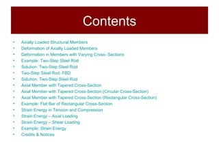
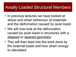
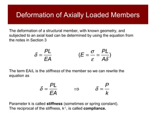
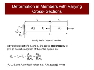
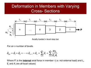
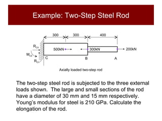
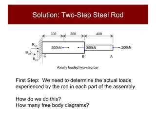

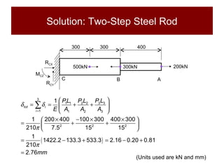
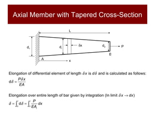

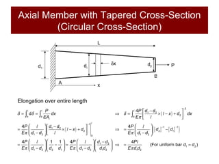


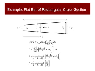
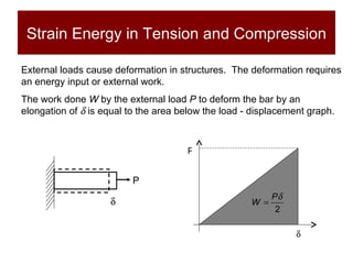
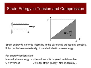
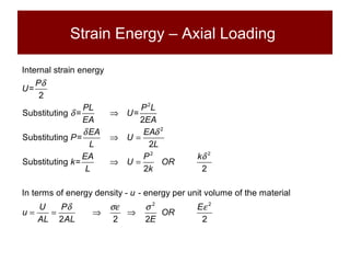

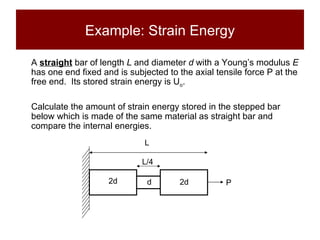
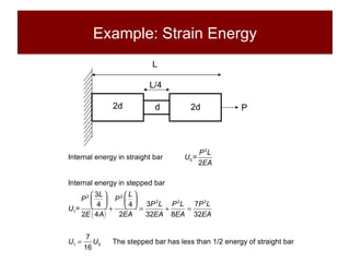

This document discusses the analysis of axially loaded structural members, focusing on the deformation of stepped and tapered rods under tension, and introduces the concept of strain energy. It includes mathematical equations for calculating elongation and strain energy in members with varying cross-sections and provides examples with detailed solutions. The document is part of educational material from Loughborough University, emphasizing the mechanics of materials under axial loads.