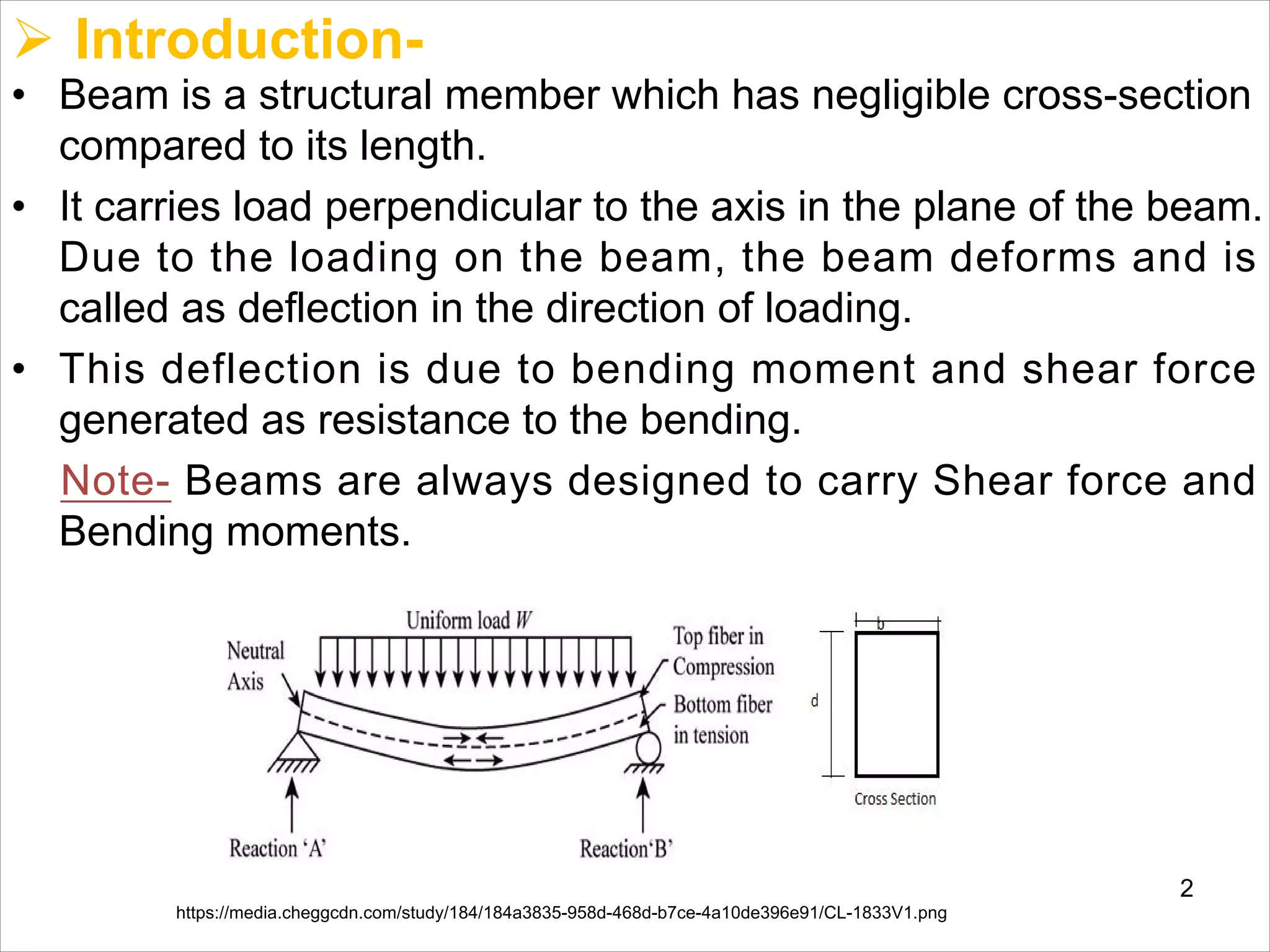
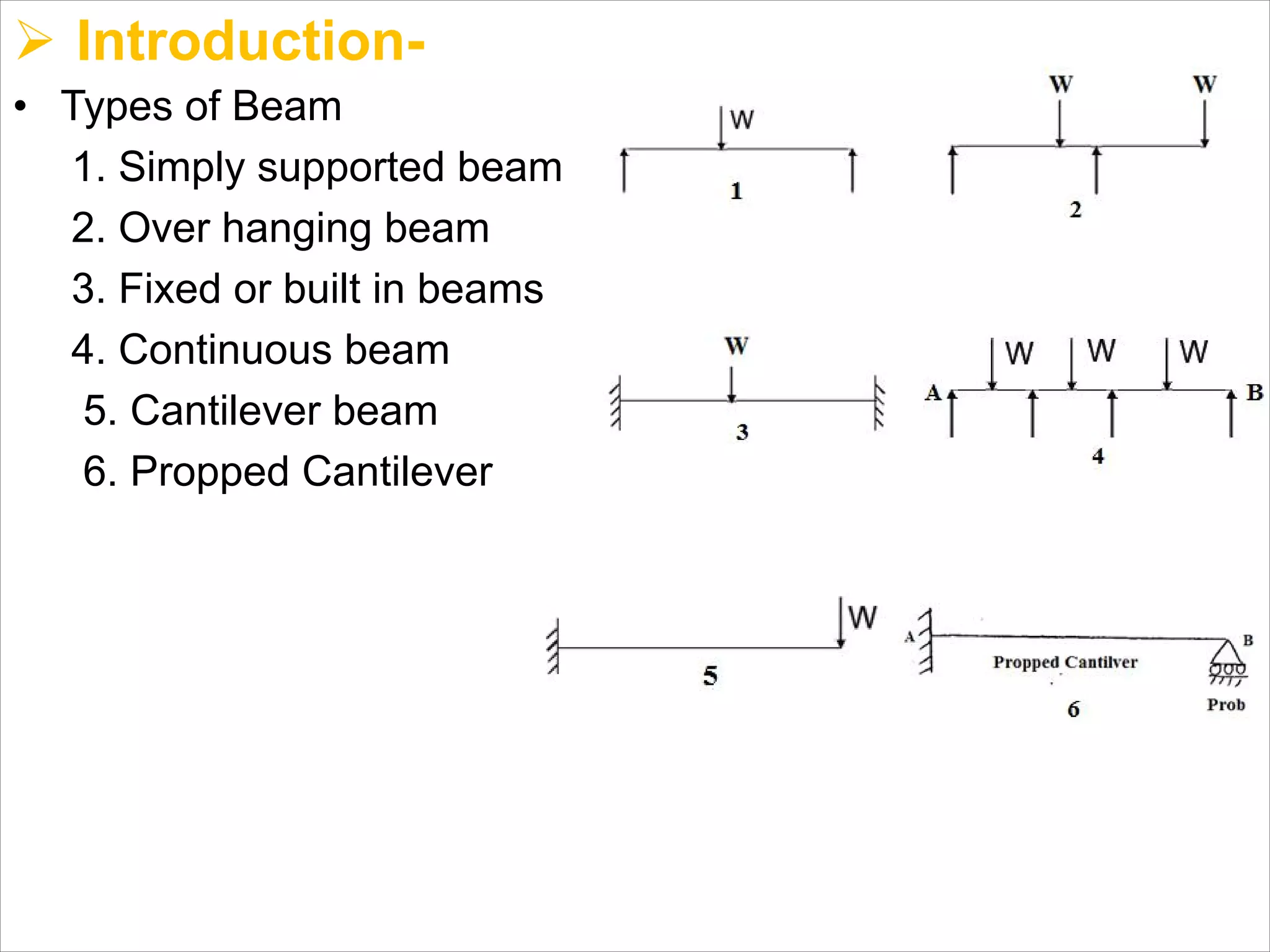
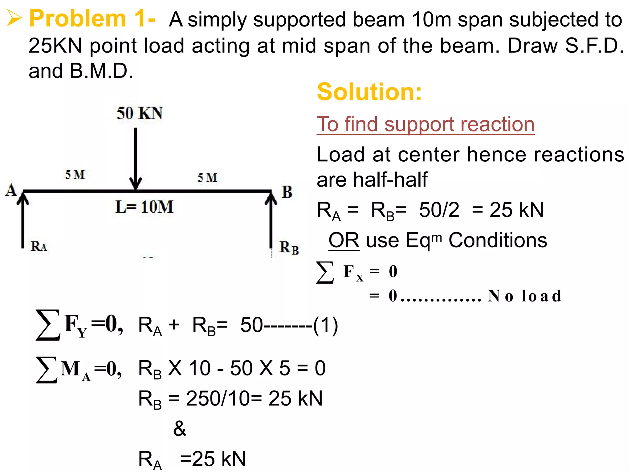
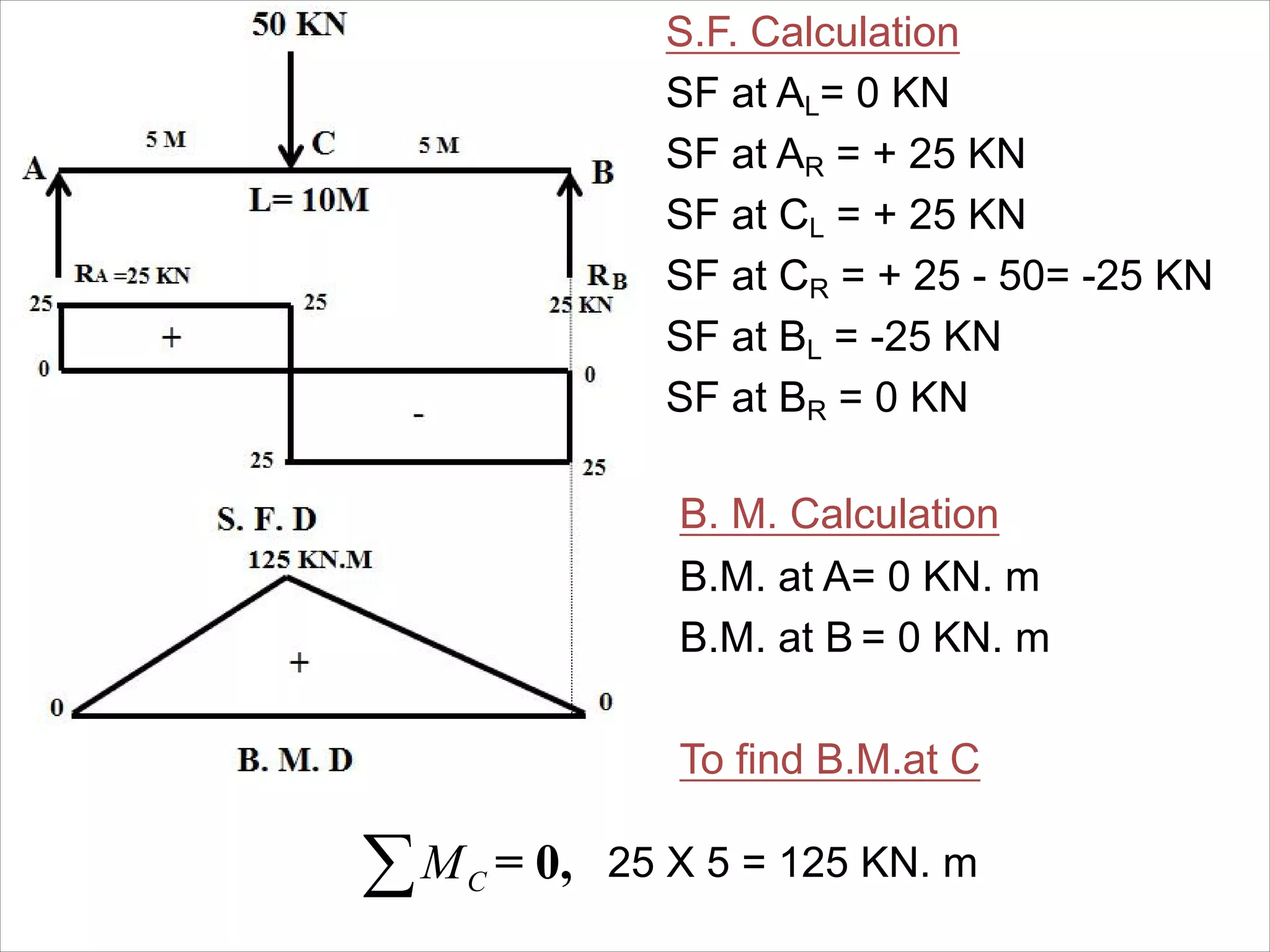
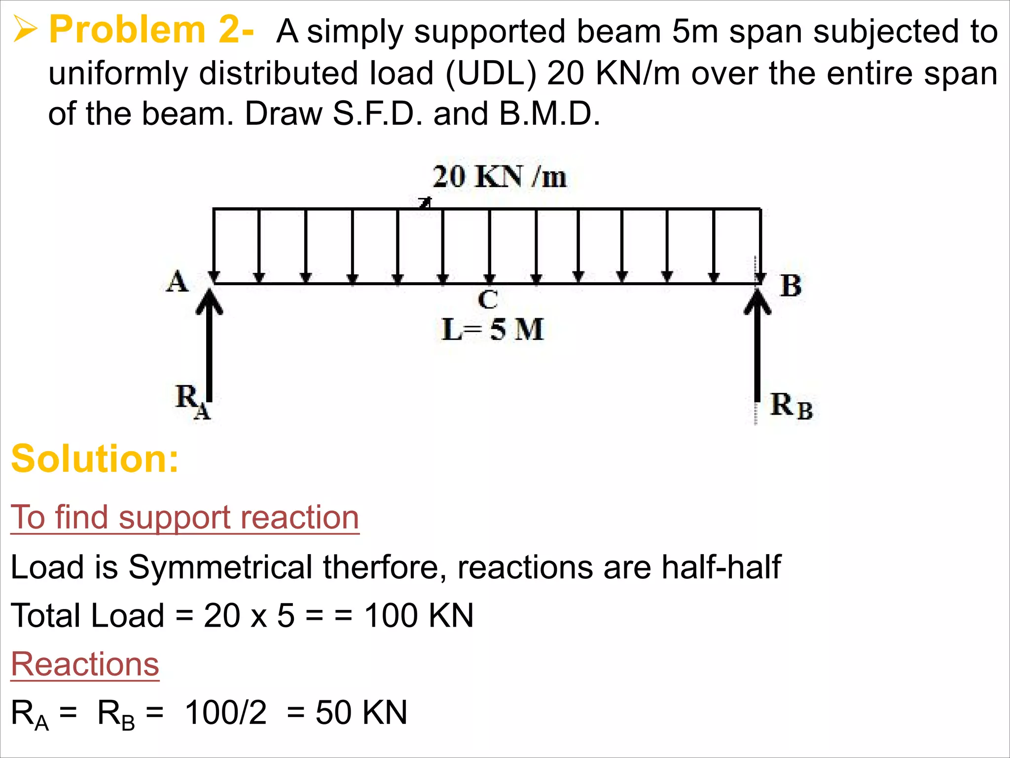
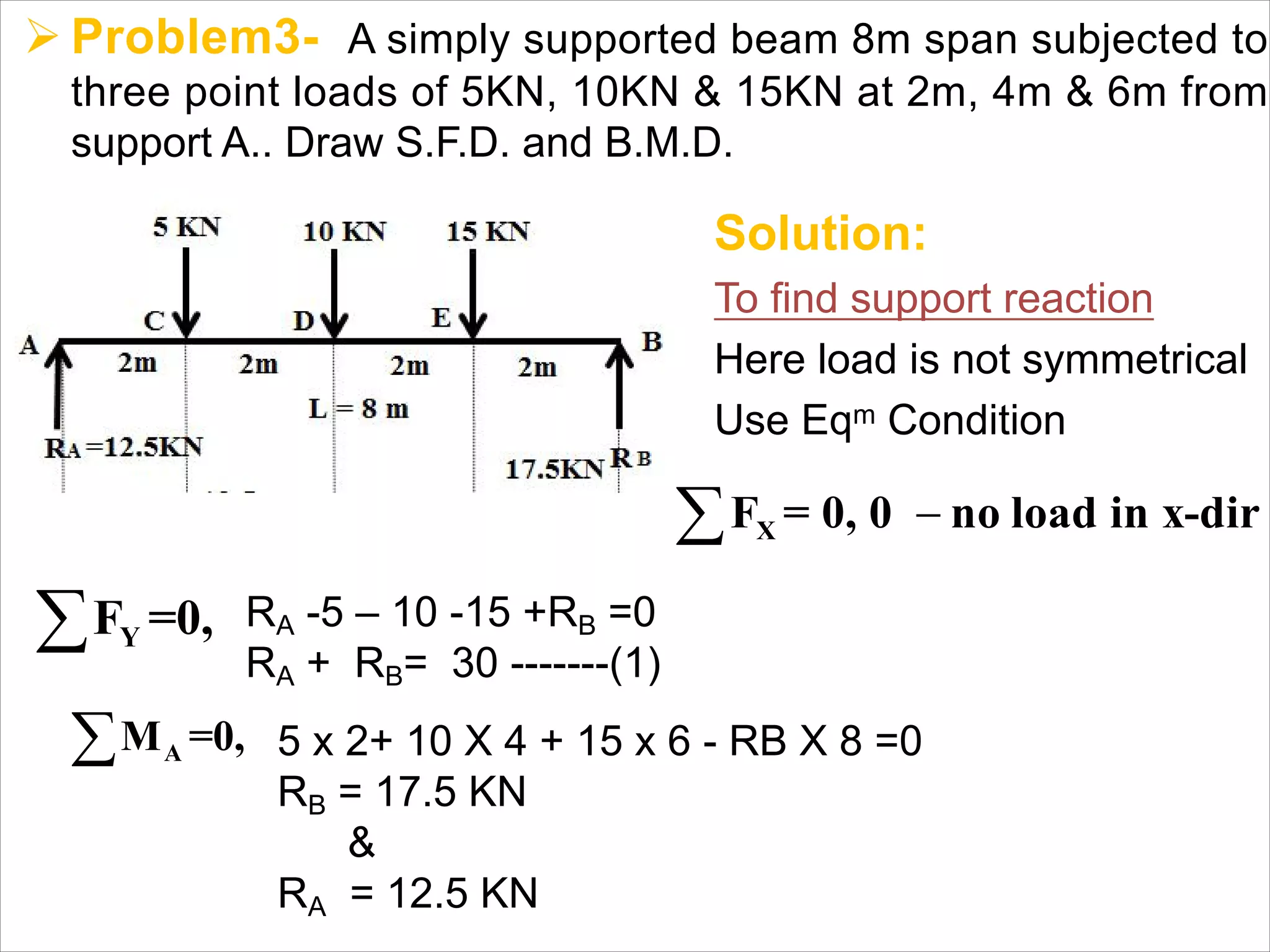
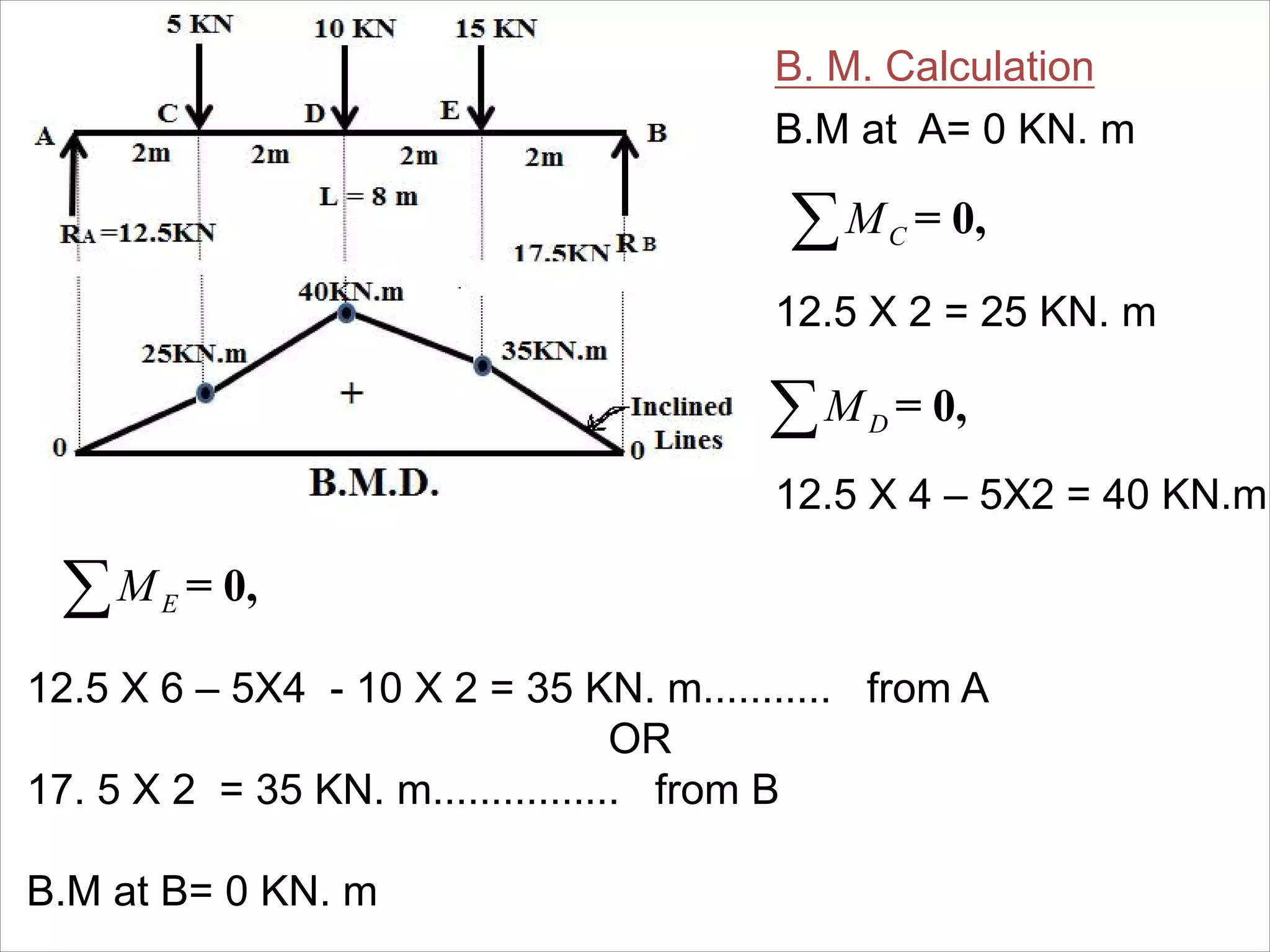
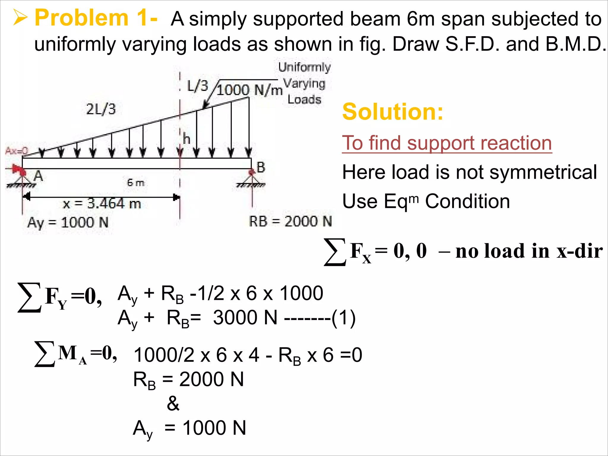
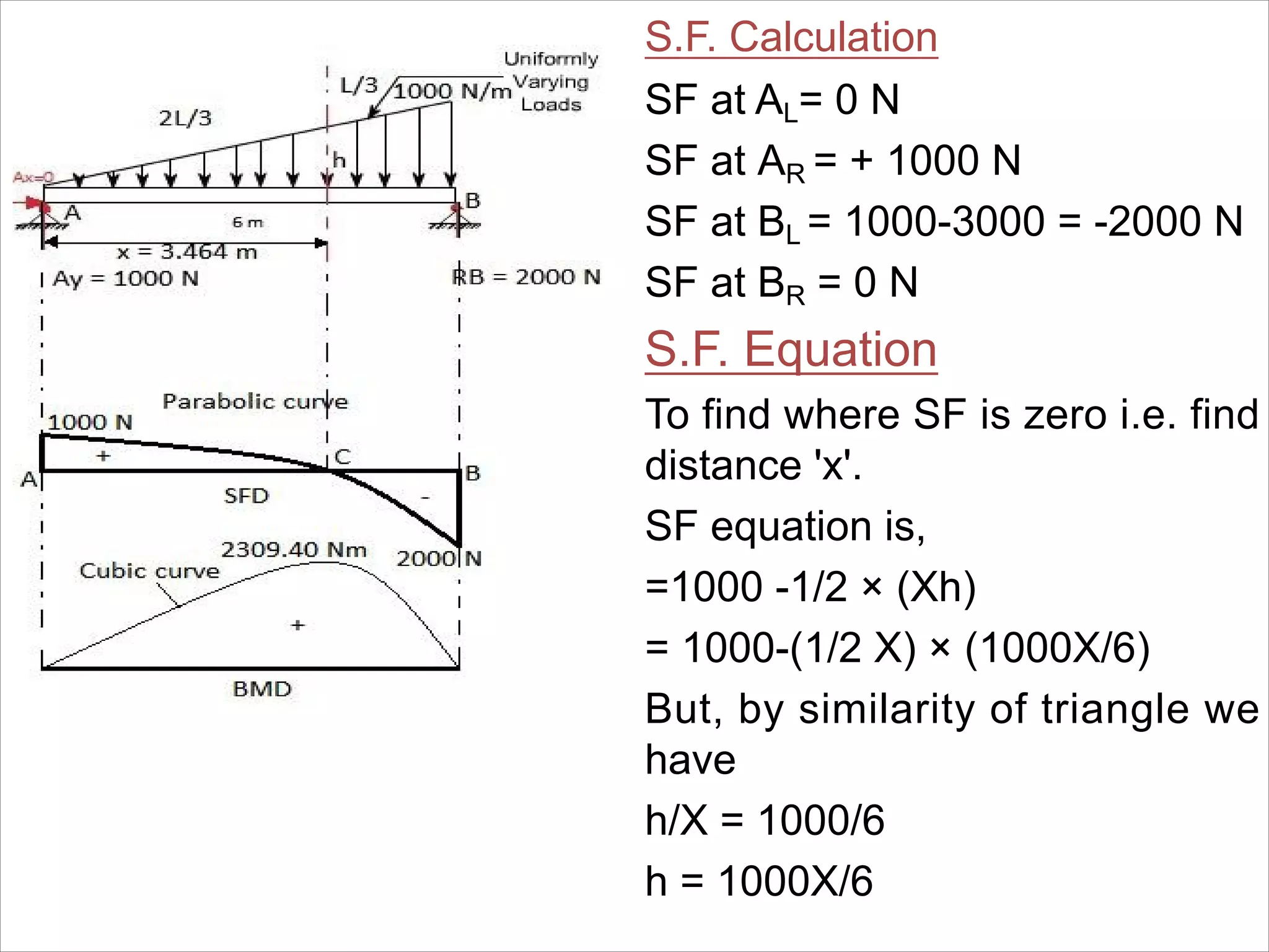
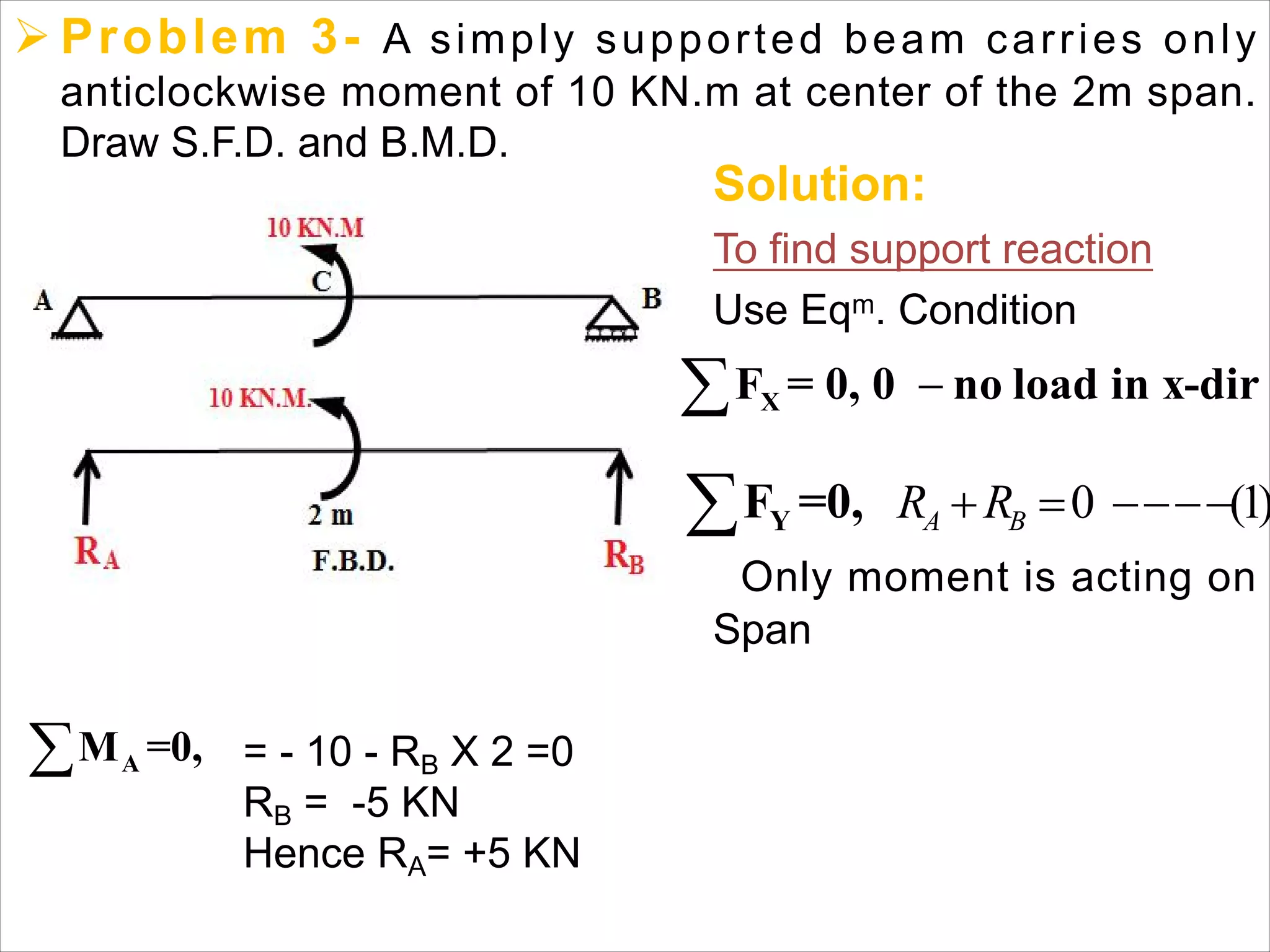
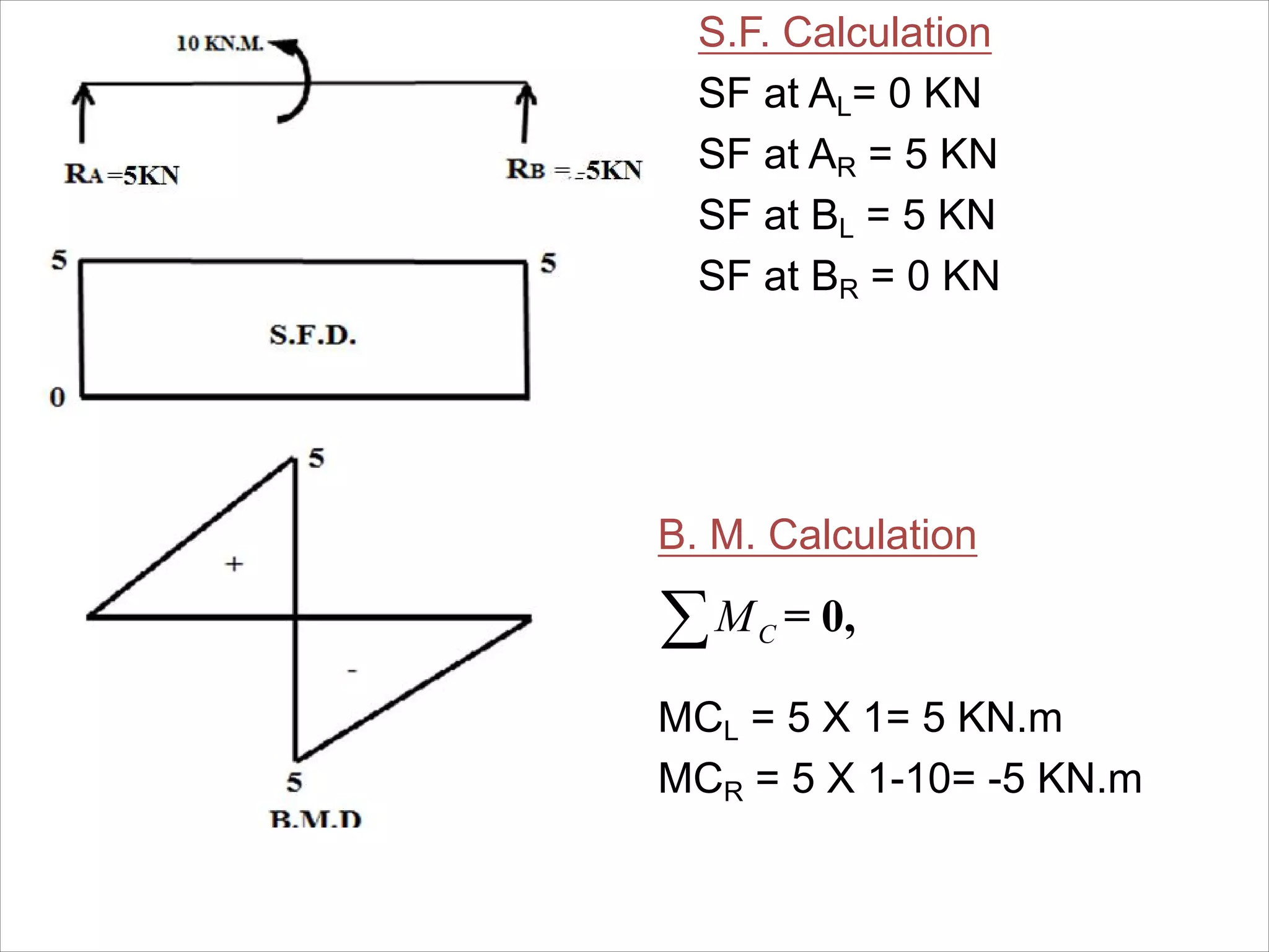
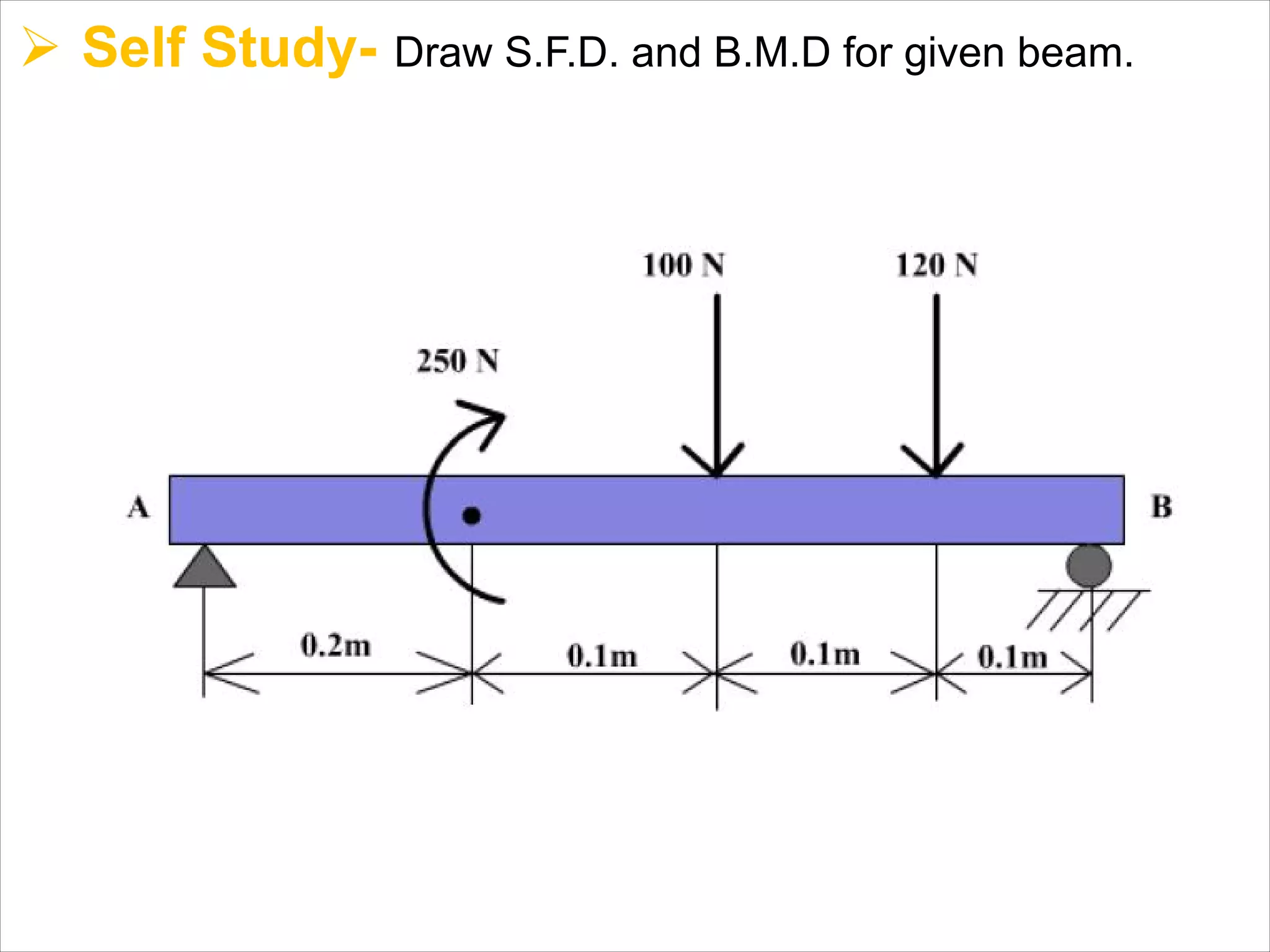
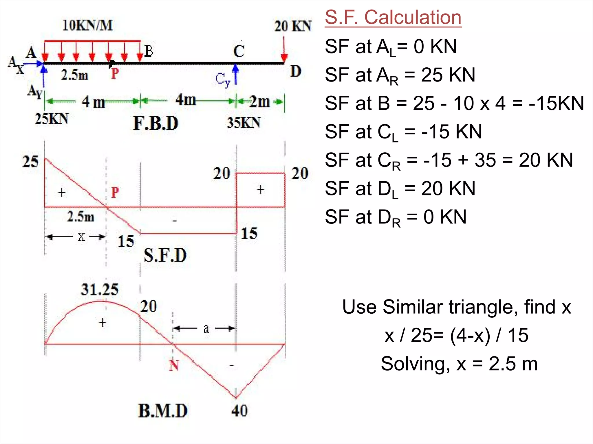
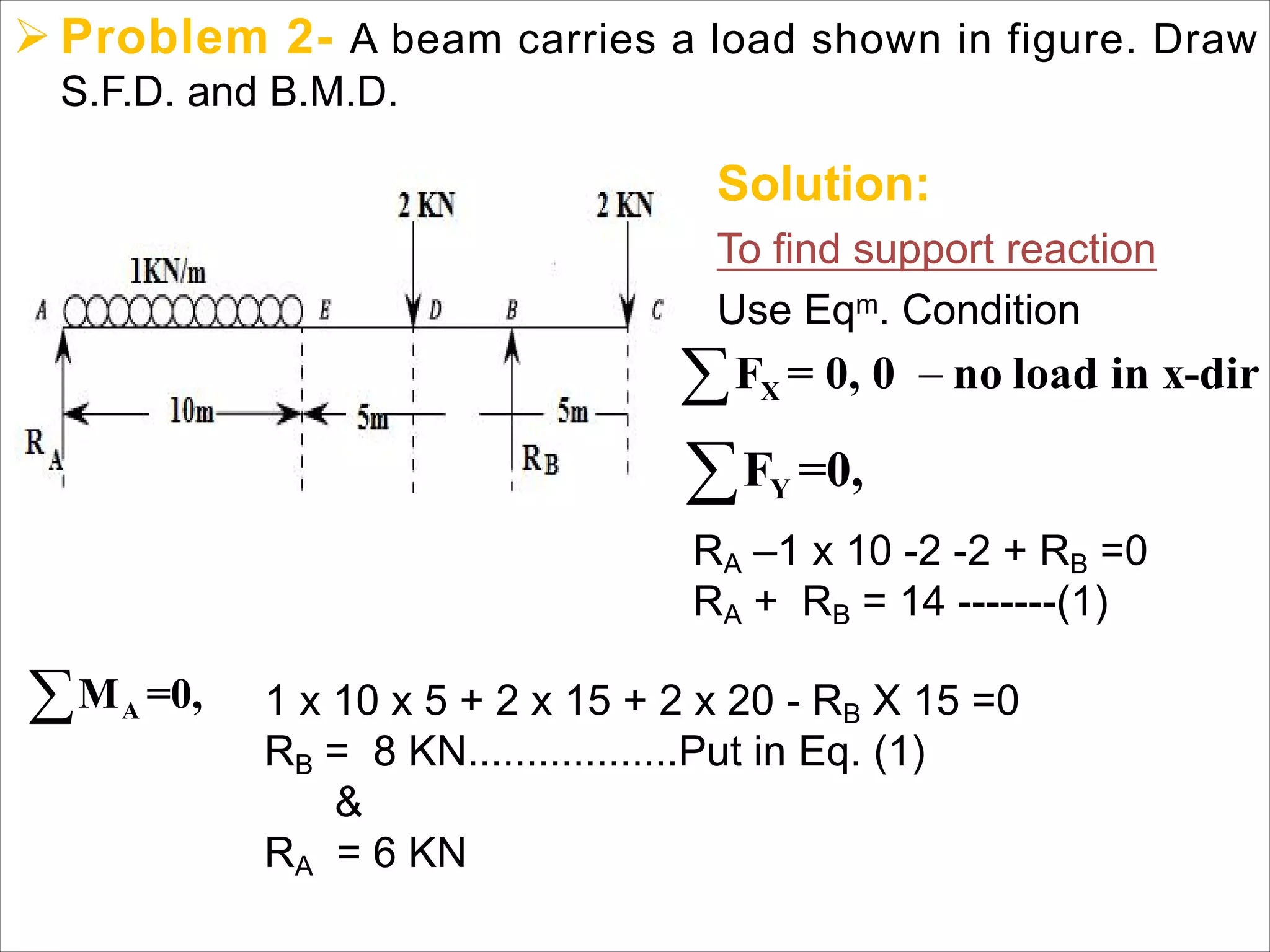
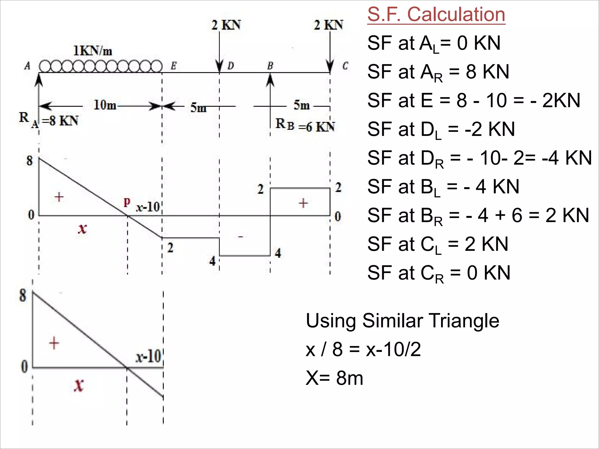
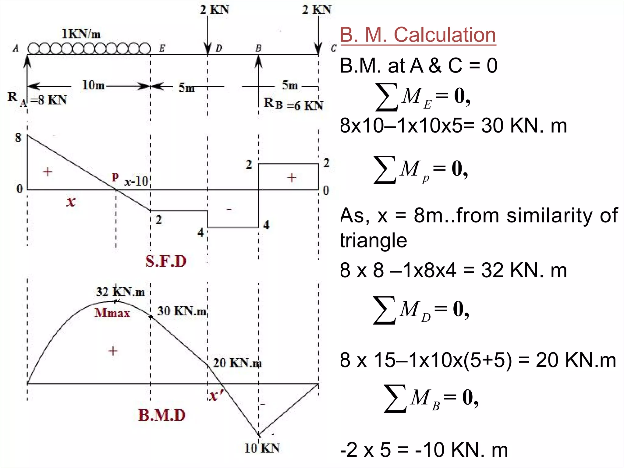
Sanjivani Rural Education Society's
Sanjivani College of Engineering, Kopargaon 423603.
-Department of Civil Engineering-
By
Mr. Sumit S. Kolapkar (Assistant Professor)
Mail Id- kolapkarsumitcivil@sanjivani.org.in
1
Ø Introduction-
• Beam is a structural member which has negligible cross-section
compared to its length.
• It carries load perpendicular to the axis in the plane of the beam.
Due to the loading on the beam, the beam deforms and is
called as deflection in the direction of loading.
• This deflection is due to bending moment and shear force
generated as resistance to the bending.
Note- Beams are always designed to carry Shear force and
Bending moments.
https://media.cheggcdn.com/study/184/184a3835-958d-468d-b7ce-4a10de396e91/CL-1833V1.png
2
Ø Introduction-
• Types of Beam
1. Simply supported beam
2. Over hanging beam
3. Fixed or built in beams
4. Continuous beam
5. Cantilever beam
6. Propped Cantilever
Ø Introduction-
• Bending Moment- Is the internal resistance moment
to counteract the external moment due to the loads.
Mathematically it is equal to algebraic sum of
moments of the loads acting on one side of the section.
It can also be defined as the unbalanced moment on
the beam at that section.
• Shear force- Is the internal resistance developed to
counteract the shearing action due to external loads.
Mathematically it is equal to algebraic sum of vertical
loads on one side of the section and this act tangential
to cross section.
4
Ø Shear Force Diagram-
• Shear force Diagram (S.F.D.)- It is the diagram drawn for a
any structural member which shows the net of shear forces
acting at various cross sections of the member.
Ø Bending Moment Diagram-
• BendingMoment Diagram- It is the diagram shows values
of the moment at the various the points of cross section.
Sagging B.M +Ve Hogging B.M. –ve
Ø Types of load-
1. Point or Concentrated load-
2. Uniformly distributed load (UDL)-
3. Uniformly varying load (UVL)-
Ø Types of Support-
1. Simple Support-
2. Roller Support or Rocker Support-
3. Hinge or Pin Support-
4. Fixed Support-
Sanjivani Rural Education Society's
Sanjivani College of Engineering, Kopargaon 423603.
-Department of Civil Engineering-
By
Mr. Sumit S. Kolapkar (Assistant Professor)
Mail Id- kolapkarsumitcivil@sanjivani.org.in
9
Ø Concept of Determinate and Indeterminate
beams-
Determinate beams:
The beams which can be analyzed just by using three equilibrium
conditions are called as determinate beams.
Maximum three unknown can be determined using Eq.
Conditions
X YF =0, F =0, and M=0,  
Indeterminate beams:
The beams which can not be analyzed just by using three
equilibrium conditions, in these beams additional conditions are
required to find unknowns are called as Indeterminate beams.
Note- 1. More than three unknown are involved in the beams.
2.Equilibrium conditions are not sufficient to solve problem.
Ø Relation Between W, S.F & B.M-
W=Rate of Loading
F = V= S.F. in kN
M = B.M. in kN. m
Rate of Change of B.M. gives S.F.
V = F = = Slope of B.M.D gives S.F.
Rate of Change of S.F. gives rate of loading
W = = Slope of S.F. gives W
For B.M. to be minimum,
dM
dx
dF
dx
0 . . 0
dM
i e F
dx
 
Ø Point of Contra flexure-
The point where the B. M. Diagram and S. F. Diagram changes
the sign is called as Point of Contra flexure.
Ø Rules for drawing SFD AND BMD-
Sr.
No
Loading
Diagram
SFD BMD
1Pt.
Load
Horizontal Line or
Zero Degree Curve
(x0)
Inclined line or
First degree curve
(x1)
2UDL Inclined line or
First degree curve
(x1)
Second degree or
Parabolic Curve
(x2)
3UVL Second degree
curve, Parabolic
Curve (x2)
Third degree or
Cubic curve
(x3)
4
Parti.
UVL
Third degree or
Cubic curve
(x3)
Fourth degree
curve
(x4)
Ø S.F.D. and B.M.D for Standard Cases-
Sanjivani Rural Education Society's
Sanjivani College of Engineering, Kopargaon 423603.
-Department of Civil Engineering-
By
Mr. Sumit S. Kolapkar (Assistant Professor)
Mail Id- kolapkarsumitcivil@sanjivani.org.in
17
Ø Problem 1- A simply supported beam 10m span subjected to
25KN point load acting at mid span of the beam. Draw S.F.D.
and B.M.D.
Solution:
To find support reaction
Load at center hence reactions
are half-half
RA = RB= 50/2 = 25 kN
OR use Eqm Conditions
 XF = 0
= 0 .............. N o lo a d
YF =0,
AM =0,
RA + RB= 50-------(1)
RB X 10 - 50 X 5 = 0
RB = 250/10= 25 kN
&
RA =25 kN
S.F. Calculation
SF at AL= 0 KN
SF at AR = + 25 KN
SF at CL = + 25 KN
SF at CR = + 25 - 50= -25 KN
SF at BL = -25 KN
SF at BR = 0 KN
B. M. Calculation
B.M. at A= 0 KN. m
B.M. at B = 0 KN. m
To find B.M.at C
= 0,CM 25 X 5 = 125 KN. m
Ø Problem 2- A simply supported beam 5m span subjected to
uniformly distributed load (UDL) 20 KN/m over the entire span
of the beam. Draw S.F.D. and B.M.D.
Solution:
To find support reaction
Load is Symmetrical therfore, reactions are half-half
Total Load = 20 x 5 = = 100 KN
Reactions
RA = RB = 100/2 = 50 KN
S.F. Calculation
SF at AL= 0 KN
SF at AR = + 50 KN
SF at BL = 50-100= -50 KN
SF at BR = 0 KN
B. M. Calculation
B.M. at A= 0 KN. m
B.M.at B = 0 KN. m
To find B.M.at C
= 0,CM 50 X 2.5 - 20 x 2.5 x 1.25 = 62.5 KN. m
Ø Problem3- A simply supported beam 8m span subjected to
three point loads of 5KN, 10KN & 15KN at 2m, 4m & 6m from
support A.. Draw S.F.D. and B.M.D.
Solution:
To find support reaction
Here load is not symmetrical
Use Eqm Condition
 XF = 0, 0 no load in x-dir
YF =0,
AM =0,
RA -5 – 10 -15 +RB =0
RA + RB= 30 -------(1)
5 x 2+ 10 X 4 + 15 x 6 - RB X 8 =0
RB = 17.5 KN
&
RA = 12.5 KN
S.F. Calculation
SF at AL= 0 KN
SF at AR = + 12.5 KN
SF at CL = + 12.5 KN
SF at CR = + 12.5 – 5 = 7.5 KN
SF at DL = 7.5 KN
SF at DR = 7.5-10= -2.5 KN
SF at EL = -2.5 KN
SF at ER = -2.5-15= - 17.5 KN
SF at BL = - 17.5 KN
SF at BR = 0 KN
B. M. Calculation
B.M at A= 0 KN. m
12.5 X 2 = 25 KN. m
12.5 X 4 – 5X2 = 40 KN.m
= 0,CM
= 0,DM
= 0,EM
12.5 X 6 – 5X4 - 10 X 2 = 35 KN. m........... from A
OR
17. 5 X 2 = 35 KN. m................ from B
B.M at B= 0 KN. m
Sanjivani Rural Education Society's
Sanjivani College of Engineering, Kopargaon 423603.
-Department of Civil Engineering-
By
Mr. Sumit S. Kolapkar (Assistant Professor)
Mail Id- kolapkarsumitcivil@sanjivani.org.in
25
Ø Problem 1- A simply supported beam 6m span subjected to
uniformly varying loads as shown in fig. Draw S.F.D. and B.M.D.
Solution:
To find support reaction
Here load is not symmetrical
Use Eqm Condition
 XF = 0, 0 no load in x-dir
YF =0,
AM =0,
Ay + RB -1/2 x 6 x 1000
Ay + RB= 3000 N -------(1)
1000/2 x 6 x 4 - RB x 6 =0
RB = 2000 N
&
Ay = 1000 N
S.F. Calculation
SF at AL= 0 N
SF at AR = + 1000 N
SF at BL = 1000-3000 = -2000 N
SF at BR = 0 N
S.F. Equation
To find where SF is zero i.e. find
distance 'x'.
SF equation is,
=1000 -1/2 × (Xh)
= 1000-(1/2 X) × (1000X/6)
But, by similarity of triangle we
have
h/X = 1000/6
h = 1000X/6
28
Equate above equation to zero
‫؞‬1000-(1/2 X) × (1000X/6) = 0
‫؞‬ X = 3.464 m....SF is zero at this
distance i.e BM is maximum.
B.M. Calculation
BM at A = 0
BM at C
BM at B = 0
N.m40.2309
3
464.3
6
464.31000
464.3
2
1
-464.31000
36
1000
2
1
-1000






 








xx
xx
Ø Problem 2- A simply supported beam 10m span subjected to
two point loads of 10KN each at 2m and 4m from support A. It
also carries the UDL of 5KN/m over a 4m from support B. span
Draw S.F.D. and B.M.D.
Solution:
To find support reaction
Use Eqm. Condition
RA -10 – 10 –(5 x 4) + RB =0
RA + RB = 40 -------(1)
10 x 2 + 10 X 4 + (5 x 4 x 8 )- RB X 10 =0
RB = 22 KN Put in Eq. (1)
&
RA = 18 KN
 XF = 0, 0 no load in x-dir
YF =0,
AM =0,
S.F. Calculation
SF at AL= 0 KN
SF at AR = + 18 KN
SF at CL = + 18 KN
SF at CR = + 18 – 10 = 8 KN
SF at DL = 8 KN
SF at DR = 8 - 10= -2 KN
SF at E = -2 KN
SF at BL = - 22 KN
SF at BR = 0 KN
B. M. Calculation
B.M. at A = 0
18 X 2 = 36 KN. m
18 X 4 – 10X2 = 52 KN.m
= 0,CM
= 0,DM
= 0,EM
18 X 6 – 10X4 - 10 X 2 = 48 KN. m
= 0,FM 22 X 2 – 5 X 2 X 1 = 34 KN. m
B. M. at B = 0
Sanjivani Rural Education Society's
Sanjivani College of Engineering, Kopargaon 423603.
-Department of Civil Engineering-
By
Mr. Sumit S. Kolapkar (Assistant Professor)
Mail Id- kolapkarsumitcivil@sanjivani.org.in
32
Ø Problem 1- A simply supported beam carries the UDL of
70KN/m over a 3m span from support A. Draw S.F.D. and
B.M.D.
Solution:
To find support reaction
Use Eqm. Condition
RA –70 x 3 + RB =0
RA + RB = 210 -------(1)
70 x 3 x 1.5 - RB X 8 =0
RB = 39.375 KN Put in Eq. (1)
&
RA = 170.625 KN and RB = 39.375 KN
 XF = 0, 0 no load in x-dir
YF =0,
AM =0,
S.F. Calculation
SF at AL= 0 KN
SF at AR = 170.625 KN
SF at C = 170.625 - 70 x 3
= - 39.375 KN
SF at BL = - 39.375 KN
SF at BR = 0 KN
To find dist. X pt. of Contra flexure,
Use Similar triangle,
x/170.625= (3-x) / 39.375
Solving, X = 2.4m
It is the dist. of pt.of contraflexure from A
B. M. Calculation
B.M. at A & B = 0
170.625 X 3 - 70 X3 X 1.5 = 196.875 KN. m
170.625 X 2.4 - 70 X 2.4 X 1.2 = 207.9 KN. m
170.625 X 1.5 – 70 X 1.5X 0.75 = 177.14 KN.m
= 0,CM
= 0,PM
1.5 = 0,MM
Ø Problem 2- A simply supported beam carries the UDL of
10KN/m over a 5m from left support A and subjected to moment
of 15 KN.m at D. Draw S.F.D. and B.M.D.
Solution:
To find support reaction
Use Eqm. Condition
RA –10 x 5 + RB =0
RA + RB = 50 -------(1)
10 x 5 x 2.5 - 15 - RB X 10 =0
RB = 11 KN........... Put in Eq. (1)
&
RA = 39 KN
 XF = 0, 0 no load in x-dir
YF =0,
AM =0,
S.F. Calculation
SF at AL= 0 KN
SF at AR =39 KN
SF at C =39-10x5 = - 11KN
SF at BL = - 11 KN
SF at BR = 0 KN
To find dist. X pt. of Contra flexure,
Use Similar triangle,
X / 39= (5-x) / 11 Solving, X = 3.9 m
It is the dist. of pt.of contraflexure from A
S.F.D
B. M. Calculation: B.M. is maximum at point 'P' Mp = Mmax
B.M. at A & B = 0
= 39 X 3.9 - 10 X3.9 X (3.9/2) = 76.05 KN. m
= 39 X 5 - 10 X 5 X 2.5 = 70 KN. m
, MDL= 39 X 7.5 – 10 X 5X 5 = 42.5 KN. m
MDR= 39 X 7.5 – 10 X 5X 5 - 15 = 27.5 KN. m
= 0,PM
= 0,Mc
= 0,DM
Ø Problem 3- A simply supported beam carries only
anticlockwise moment of 10 KN.m at center of the 2m span.
Draw S.F.D. and B.M.D.
Solution:
To find support reaction
Use Eqm. Condition
Only moment is acting on
Span
= - 10 - RB X 2 =0
RB = -5 KN
Hence RA= +5 KN
0 (1)A BR R  
 XF = 0, 0 no load in x-dir
YF =0,
AM =0,
= 0,CM
S.F. Calculation
SF at AL= 0 KN
SF at AR = 5 KN
SF at BL = 5 KN
SF at BR = 0 KN
B. M. Calculation
MCL = 5 X 1= 5 KN.m
MCR = 5 X 1-10= -5 KN.m
Ø Self Study- Draw S.F.D. and B.M.D for given beam.
Sanjivani Rural Education Society's
Sanjivani College of Engineering, Kopargaon 423603.
-Department of Civil Engineering-
By
Mr. Sumit S. Kolapkar (Assistant Professor)
Mail Id- kolapkarsumitcivil@sanjivani.org.in
42
Ø Problem 1- A overhanging beam 10m span subjected to udl
10KN/m over a span of 4m from support A. It also carries a
point load 20KN at point D. Draw S.F.D. and B.M.D.
Solution:
To find support reaction
Use Eqm. Condition
Ay -10 X 4 – 20 + Cy =0
Ay + Cy = 60 -------(1)
10 x 4 x 2 + 20 X 10 - Cy X 8 =0
Cy = 35 KN............Put in Eq. (1)
&
Ay =25 KN
 XF = 0, 0 no load in x-dir
YF =0,
AM =0,
S.F. Calculation
SF at AL= 0 KN
SF at AR = 25 KN
SF at B = 25 - 10 x 4 = -15KN
SF at CL = -15 KN
SF at CR = -15 + 35 = 20 KN
SF at DL = 20 KN
SF at DR = 0 KN
Use Similar triangle, find x
x / 25= (4-x) / 15
Solving, x = 2.5 m
B. M. Calculation
B.M. at A & D = 0
25 X 4 – 10 x 4 x 2= 20 KN. m
25X2.5-10X2.5x1.25=31.25KN.m
= 0,BM
= 0,pM
= 0,cM
-20 x 2 = - 40KN.m... Cantilever -ve
(N= Point of Contra flexure)
Use Similar Triangle in BMD a / 40 = (4-a) / 20
Solving, a = 2.66 m...from 'C'
Ø Problem 2- A beam carries a load shown in figure. Draw
S.F.D. and B.M.D.
Solution:
To find support reaction
Use Eqm. Condition
RA –1 x 10 -2 -2 + RB =0
RA + RB = 14 -------(1)
1 x 10 x 5 + 2 x 15 + 2 x 20 - RB X 15 =0
RB = 8 KN..................Put in Eq. (1)
&
RA = 6 KN
 XF = 0, 0 no load in x-dir
YF =0,
AM =0,
S.F. Calculation
SF at AL= 0 KN
SF at AR = 8 KN
SF at E = 8 - 10 = - 2KN
SF at DL = -2 KN
SF at DR = - 10- 2= -4 KN
SF at BL = - 4 KN
SF at BR = - 4 + 6 = 2 KN
SF at CL = 2 KN
SF at CR = 0 KN
Using Similar Triangle
x / 8 = x-10/2
X= 8m
B. M. Calculation
B.M. at A & C = 0
8x10–1x10x5= 30 KN. m
As, x = 8m..from similarity of
triangle
8 x 8 –1x8x4 = 32 KN. m
8 x 15–1x10x(5+5) = 20 KN.m
-2 x 5 = -10 KN. m
= 0,EM
= 0,pM
= 0,BM
DM = 0,
Ø Problem 3- A simply supported beam carries a load shown in
figure. Draw S.F.D. and B.M.D.
To find support reaction
Use Eqm. Condition
RB – 5 x 0.7 - 4 - 2-1 + RF =0
RB + RF = 10.5 -------(1)
= - 1 x 0.7 + 5 x 0.7x (0.35+0.4) + 4 x 1.5 + 2 x 2.5 - RF
X 1.9 =0
RB = 3.7 KN..................Put in Eq. (1)
& RA = 6.8 KN
 XF = 0, 0 no load in x-dir
YF =0,
 BM =0,
S.F. Calculation
SF at AL= 0 KN
SF at AR = -1 KN
SF at BL = - 1 KN
SF at BR = -1+3.7= 2.7 KN
SF at C = 2.7 KN
SF at D = - 0.8 KN
SF at EL = - 0.8 KN
SF at ER = -0.8 - 4= -4.8 KN
SF at FL = -4.8 KN
SF at FR = -4.8+6.8=2 KN
SF at GL = 2 KN
SF at GR = 0 KN
By similarity of triangle we have,
d/0.8 = (0.7-d)/2.7
d = 0.16 m.....from 'D'
OR
x =1.64 m from 'A'
S.F.D
B. M. Calculation:
B.M. at A & G = 0
= -1 X 0.7 = - 0.7KN. m
= -2 X 0.6 = - 1.2KN. m
= -1 X 1.1 + 3.7 X 0.4= 0.38 KN. m
= -1 X 1.8 + 3.7 X 1.1 - 5 X 0.7 X 0.35= 1.05 KN. m
= -2 X 1 + 6.8 x 0.4 = 0.73 KN. m
= -1x1.64 + (3.7x0.94)-(5 x 0.54 x 0.27) =1.109 KN.m
= 0,BM
= 0,FM
= 0,CM
= 0,DM
= 0,EM
pM = 0,
Ø Self study- Draw SFD and BMD
Solution
Sanjivani Rural Education Society's
Sanjivani College of Engineering, Kopargaon 423603.
-Department of Civil Engineering-
By
Mr. Sumit S. Kolapkar (Assistant Professor)
Mail Id- kolapkarsumitcivil@sanjivani.org.in
54
Ø Cantilever beam- One end of the beam is fixed and other
end is free.
Note- Three unknowns at fixed end
Ø Cantilever beam with Uniformly Varying Load
(UVL)-
Ø Problem1- A Cantilever beam 5m span subjected to point
load of 10KN. Draw S.F.D. and B.M.D.
Solution:
To find reactions
Use Eqm. Condition
Ay -10 =0
Ay = 10 -------(1)
-MA + 10 x 5 = 0
MA = 50 KN.m
 XF = 0, 0 no load in x-dir
YF =0,
AM =0,
S.F. Calculation
SF at AL= 0 KN
SF at AR = 10 KN
SF at BL = 10 KN
SF at BR = 0 KN
B. M Calculation
B.M. at B = 0
= 0,AM
-MA + 10 x 5 = 0
MA = 50 KN.M
To find reactions Use Eqm. Condition
= 0, Ax=0XF
YF =0, Ay - 20 x 4 - 50 = 0
Ay = 130 KN
-MA +(20x4x4) + 50x8 = 0 i.e. MA = 720 KN.mAM =0,
Ø Problem 2- Draw S.F.D. and B.M.D for a Cantilever beam of
8m span subjected to point load 50KN at free end and UDL of
20KN/m over a span of 4m as shown in figure.
S.F. Calculation
SF at AL= 0 KN
SF at AR = 130 KN
SF at B = 130KN
SF at D = 130- 20x 4= 50 KN
SF at EL = 50 KN
SF at ER = 0 KN
B. M. Calculation
B.M. at E = 0
-50X2= –100KN. m
-50x6 - 20x4x2 =-460 KN.m
= 0,DM
= 0,BM
ARM =0, = -720 KN.mALM = 0,
Sanjivani Rural Education Society's
Sanjivani College of Engineering, Kopargaon 423603.
-Department of Civil Engineering-
By
Mr. Sumit S. Kolapkar (Assistant Professor)
Mail Id- kolapkarsumitcivil@sanjivani.org.in
62
1. If SFD is Horizontal Line- No load in that region
2. If SFD is Inclined Line- Loading Diagram UDL
3. If SFD is Parabolic- Loading Diagram UVL
4. If Vertical step in SFD–Point load in Loading dia.
Ø Loading Diagram From S.F.D-
Ø S.F.D From B.M.D-
1. If BMD is Horizontal Line- No Shear Force in that region
2. If BMD is Inclined Line- S.F horizontal line
3. If BMD is Parabolic- S.F Inclined line
4. If Vertical step in BMD– No effect in SFD,
Moment of couple in Loading dia.
Ø Problem1- A beam AB is simply supported at ends for which
SFD is drawn shown in Fig. Draw Loading diagram.
1. Vertical rise at A indicates reaction at A
RA = 11.5KN
2. Inclined Line AC- Indicates UDL Intensity
= 11.5 - 7.5/2 = 2 KN/m
3. Inclined Line CD- Indicates UDL Intensity
= 7.5-3.5/1 = 4 KN/m
Ø Problem1- A beam AB is simply supported at ends for which
SFD is drawn shown in Fig. Draw Loading diagram.
4. Sudden down at D - Indicates Point Load-
= 3.5+2.5= 6KN
5. Inclined Line DB- UDL Intensity
= -2.5-(-6.5) /1 = 4KN/m
6. Sudden rise at B shows the Reaction at B
RB = 6.5KN
Ø Problem2- A beam AD is simply supported at ends for which
SFD is as shown in Fig. Draw Loading diagram & B.M.D.
At point A Sudden rise of
4000N indicates Reaction
RA at A.
RA = 4000N
1. Inclined line between portion AB Indicates
UDL Intensity
= 4000-0 / 10 = 400 N/M
2. Horizontal Line in BC- No load
3. Sudden down at C - Point Load of 4000N
4. Sudden rise at D – Reaction at D of 4000N
1.UDL = 400 N/M
2. Horizontalz Line BC- No
load
3. Sudden down at C - Point
Load of 4000N
4. Reaction at D of 4000N
4000x10- 400x10x5
MB =20,000N.m
4000x15- 400x10x 10
MC =20,000N.m
 BM =0,
 CM =0,
AM =0,  DM =0,
• In fixed beam both ends of the beam are fixed i.e. ends are
restricted or restrained from rotation. It means slope is zero at
the ends but B.M. is not zero.
• At every end there are three unknowns. That means total six
unknown at both ends.
• Fixed beams are statically indeterminate, means this type of
beam can not be solved by using equilibrium conditions.
Ø Concept of fixed beam-
THANK YOU...
70

Shear Force and Bending Moment Diagram

  • 1.
    Sanjivani Rural EducationSociety's Sanjivani College of Engineering, Kopargaon 423603. -Department of Civil Engineering- By Mr. Sumit S. Kolapkar (Assistant Professor) Mail Id- kolapkarsumitcivil@sanjivani.org.in 1
  • 2.
    Ø Introduction- • Beamis a structural member which has negligible cross-section compared to its length. • It carries load perpendicular to the axis in the plane of the beam. Due to the loading on the beam, the beam deforms and is called as deflection in the direction of loading. • This deflection is due to bending moment and shear force generated as resistance to the bending. Note- Beams are always designed to carry Shear force and Bending moments. https://media.cheggcdn.com/study/184/184a3835-958d-468d-b7ce-4a10de396e91/CL-1833V1.png 2
  • 3.
    Ø Introduction- • Typesof Beam 1. Simply supported beam 2. Over hanging beam 3. Fixed or built in beams 4. Continuous beam 5. Cantilever beam 6. Propped Cantilever
  • 4.
    Ø Introduction- • BendingMoment- Is the internal resistance moment to counteract the external moment due to the loads. Mathematically it is equal to algebraic sum of moments of the loads acting on one side of the section. It can also be defined as the unbalanced moment on the beam at that section. • Shear force- Is the internal resistance developed to counteract the shearing action due to external loads. Mathematically it is equal to algebraic sum of vertical loads on one side of the section and this act tangential to cross section. 4
  • 5.
    Ø Shear ForceDiagram- • Shear force Diagram (S.F.D.)- It is the diagram drawn for a any structural member which shows the net of shear forces acting at various cross sections of the member.
  • 6.
    Ø Bending MomentDiagram- • BendingMoment Diagram- It is the diagram shows values of the moment at the various the points of cross section. Sagging B.M +Ve Hogging B.M. –ve
  • 7.
    Ø Types ofload- 1. Point or Concentrated load- 2. Uniformly distributed load (UDL)- 3. Uniformly varying load (UVL)-
  • 8.
    Ø Types ofSupport- 1. Simple Support- 2. Roller Support or Rocker Support- 3. Hinge or Pin Support- 4. Fixed Support-
  • 9.
    Sanjivani Rural EducationSociety's Sanjivani College of Engineering, Kopargaon 423603. -Department of Civil Engineering- By Mr. Sumit S. Kolapkar (Assistant Professor) Mail Id- kolapkarsumitcivil@sanjivani.org.in 9
  • 10.
    Ø Concept ofDeterminate and Indeterminate beams- Determinate beams: The beams which can be analyzed just by using three equilibrium conditions are called as determinate beams. Maximum three unknown can be determined using Eq. Conditions X YF =0, F =0, and M=0,   Indeterminate beams: The beams which can not be analyzed just by using three equilibrium conditions, in these beams additional conditions are required to find unknowns are called as Indeterminate beams. Note- 1. More than three unknown are involved in the beams. 2.Equilibrium conditions are not sufficient to solve problem.
  • 11.
    Ø Relation BetweenW, S.F & B.M- W=Rate of Loading F = V= S.F. in kN M = B.M. in kN. m Rate of Change of B.M. gives S.F. V = F = = Slope of B.M.D gives S.F. Rate of Change of S.F. gives rate of loading W = = Slope of S.F. gives W For B.M. to be minimum, dM dx dF dx 0 . . 0 dM i e F dx  
  • 12.
    Ø Point ofContra flexure- The point where the B. M. Diagram and S. F. Diagram changes the sign is called as Point of Contra flexure.
  • 13.
    Ø Rules fordrawing SFD AND BMD- Sr. No Loading Diagram SFD BMD 1Pt. Load Horizontal Line or Zero Degree Curve (x0) Inclined line or First degree curve (x1) 2UDL Inclined line or First degree curve (x1) Second degree or Parabolic Curve (x2) 3UVL Second degree curve, Parabolic Curve (x2) Third degree or Cubic curve (x3) 4 Parti. UVL Third degree or Cubic curve (x3) Fourth degree curve (x4)
  • 14.
    Ø S.F.D. andB.M.D for Standard Cases-
  • 15.
    Ø S.F.D. andB.M.D for Standard Cases-
  • 16.
    Ø S.F.D. andB.M.D for Standard Cases-
  • 17.
    Sanjivani Rural EducationSociety's Sanjivani College of Engineering, Kopargaon 423603. -Department of Civil Engineering- By Mr. Sumit S. Kolapkar (Assistant Professor) Mail Id- kolapkarsumitcivil@sanjivani.org.in 17
  • 18.
    Ø Problem 1-A simply supported beam 10m span subjected to 25KN point load acting at mid span of the beam. Draw S.F.D. and B.M.D. Solution: To find support reaction Load at center hence reactions are half-half RA = RB= 50/2 = 25 kN OR use Eqm Conditions  XF = 0 = 0 .............. N o lo a d YF =0, AM =0, RA + RB= 50-------(1) RB X 10 - 50 X 5 = 0 RB = 250/10= 25 kN & RA =25 kN
  • 19.
    S.F. Calculation SF atAL= 0 KN SF at AR = + 25 KN SF at CL = + 25 KN SF at CR = + 25 - 50= -25 KN SF at BL = -25 KN SF at BR = 0 KN B. M. Calculation B.M. at A= 0 KN. m B.M. at B = 0 KN. m To find B.M.at C = 0,CM 25 X 5 = 125 KN. m
  • 20.
    Ø Problem 2-A simply supported beam 5m span subjected to uniformly distributed load (UDL) 20 KN/m over the entire span of the beam. Draw S.F.D. and B.M.D. Solution: To find support reaction Load is Symmetrical therfore, reactions are half-half Total Load = 20 x 5 = = 100 KN Reactions RA = RB = 100/2 = 50 KN
  • 21.
    S.F. Calculation SF atAL= 0 KN SF at AR = + 50 KN SF at BL = 50-100= -50 KN SF at BR = 0 KN B. M. Calculation B.M. at A= 0 KN. m B.M.at B = 0 KN. m To find B.M.at C = 0,CM 50 X 2.5 - 20 x 2.5 x 1.25 = 62.5 KN. m
  • 22.
    Ø Problem3- Asimply supported beam 8m span subjected to three point loads of 5KN, 10KN & 15KN at 2m, 4m & 6m from support A.. Draw S.F.D. and B.M.D. Solution: To find support reaction Here load is not symmetrical Use Eqm Condition  XF = 0, 0 no load in x-dir YF =0, AM =0, RA -5 – 10 -15 +RB =0 RA + RB= 30 -------(1) 5 x 2+ 10 X 4 + 15 x 6 - RB X 8 =0 RB = 17.5 KN & RA = 12.5 KN
  • 23.
    S.F. Calculation SF atAL= 0 KN SF at AR = + 12.5 KN SF at CL = + 12.5 KN SF at CR = + 12.5 – 5 = 7.5 KN SF at DL = 7.5 KN SF at DR = 7.5-10= -2.5 KN SF at EL = -2.5 KN SF at ER = -2.5-15= - 17.5 KN SF at BL = - 17.5 KN SF at BR = 0 KN
  • 24.
    B. M. Calculation B.Mat A= 0 KN. m 12.5 X 2 = 25 KN. m 12.5 X 4 – 5X2 = 40 KN.m = 0,CM = 0,DM = 0,EM 12.5 X 6 – 5X4 - 10 X 2 = 35 KN. m........... from A OR 17. 5 X 2 = 35 KN. m................ from B B.M at B= 0 KN. m
  • 25.
    Sanjivani Rural EducationSociety's Sanjivani College of Engineering, Kopargaon 423603. -Department of Civil Engineering- By Mr. Sumit S. Kolapkar (Assistant Professor) Mail Id- kolapkarsumitcivil@sanjivani.org.in 25
  • 26.
    Ø Problem 1-A simply supported beam 6m span subjected to uniformly varying loads as shown in fig. Draw S.F.D. and B.M.D. Solution: To find support reaction Here load is not symmetrical Use Eqm Condition  XF = 0, 0 no load in x-dir YF =0, AM =0, Ay + RB -1/2 x 6 x 1000 Ay + RB= 3000 N -------(1) 1000/2 x 6 x 4 - RB x 6 =0 RB = 2000 N & Ay = 1000 N
  • 27.
    S.F. Calculation SF atAL= 0 N SF at AR = + 1000 N SF at BL = 1000-3000 = -2000 N SF at BR = 0 N S.F. Equation To find where SF is zero i.e. find distance 'x'. SF equation is, =1000 -1/2 × (Xh) = 1000-(1/2 X) × (1000X/6) But, by similarity of triangle we have h/X = 1000/6 h = 1000X/6
  • 28.
    28 Equate above equationto zero ‫؞‬1000-(1/2 X) × (1000X/6) = 0 ‫؞‬ X = 3.464 m....SF is zero at this distance i.e BM is maximum. B.M. Calculation BM at A = 0 BM at C BM at B = 0 N.m40.2309 3 464.3 6 464.31000 464.3 2 1 -464.31000 36 1000 2 1 -1000                 xx xx
  • 29.
    Ø Problem 2-A simply supported beam 10m span subjected to two point loads of 10KN each at 2m and 4m from support A. It also carries the UDL of 5KN/m over a 4m from support B. span Draw S.F.D. and B.M.D. Solution: To find support reaction Use Eqm. Condition RA -10 – 10 –(5 x 4) + RB =0 RA + RB = 40 -------(1) 10 x 2 + 10 X 4 + (5 x 4 x 8 )- RB X 10 =0 RB = 22 KN Put in Eq. (1) & RA = 18 KN  XF = 0, 0 no load in x-dir YF =0, AM =0,
  • 30.
    S.F. Calculation SF atAL= 0 KN SF at AR = + 18 KN SF at CL = + 18 KN SF at CR = + 18 – 10 = 8 KN SF at DL = 8 KN SF at DR = 8 - 10= -2 KN SF at E = -2 KN SF at BL = - 22 KN SF at BR = 0 KN
  • 31.
    B. M. Calculation B.M.at A = 0 18 X 2 = 36 KN. m 18 X 4 – 10X2 = 52 KN.m = 0,CM = 0,DM = 0,EM 18 X 6 – 10X4 - 10 X 2 = 48 KN. m = 0,FM 22 X 2 – 5 X 2 X 1 = 34 KN. m B. M. at B = 0
  • 32.
    Sanjivani Rural EducationSociety's Sanjivani College of Engineering, Kopargaon 423603. -Department of Civil Engineering- By Mr. Sumit S. Kolapkar (Assistant Professor) Mail Id- kolapkarsumitcivil@sanjivani.org.in 32
  • 33.
    Ø Problem 1-A simply supported beam carries the UDL of 70KN/m over a 3m span from support A. Draw S.F.D. and B.M.D. Solution: To find support reaction Use Eqm. Condition RA –70 x 3 + RB =0 RA + RB = 210 -------(1) 70 x 3 x 1.5 - RB X 8 =0 RB = 39.375 KN Put in Eq. (1) & RA = 170.625 KN and RB = 39.375 KN  XF = 0, 0 no load in x-dir YF =0, AM =0,
  • 34.
    S.F. Calculation SF atAL= 0 KN SF at AR = 170.625 KN SF at C = 170.625 - 70 x 3 = - 39.375 KN SF at BL = - 39.375 KN SF at BR = 0 KN To find dist. X pt. of Contra flexure, Use Similar triangle, x/170.625= (3-x) / 39.375 Solving, X = 2.4m It is the dist. of pt.of contraflexure from A
  • 35.
    B. M. Calculation B.M.at A & B = 0 170.625 X 3 - 70 X3 X 1.5 = 196.875 KN. m 170.625 X 2.4 - 70 X 2.4 X 1.2 = 207.9 KN. m 170.625 X 1.5 – 70 X 1.5X 0.75 = 177.14 KN.m = 0,CM = 0,PM 1.5 = 0,MM
  • 36.
    Ø Problem 2-A simply supported beam carries the UDL of 10KN/m over a 5m from left support A and subjected to moment of 15 KN.m at D. Draw S.F.D. and B.M.D. Solution: To find support reaction Use Eqm. Condition RA –10 x 5 + RB =0 RA + RB = 50 -------(1) 10 x 5 x 2.5 - 15 - RB X 10 =0 RB = 11 KN........... Put in Eq. (1) & RA = 39 KN  XF = 0, 0 no load in x-dir YF =0, AM =0,
  • 37.
    S.F. Calculation SF atAL= 0 KN SF at AR =39 KN SF at C =39-10x5 = - 11KN SF at BL = - 11 KN SF at BR = 0 KN To find dist. X pt. of Contra flexure, Use Similar triangle, X / 39= (5-x) / 11 Solving, X = 3.9 m It is the dist. of pt.of contraflexure from A
  • 38.
    S.F.D B. M. Calculation:B.M. is maximum at point 'P' Mp = Mmax B.M. at A & B = 0 = 39 X 3.9 - 10 X3.9 X (3.9/2) = 76.05 KN. m = 39 X 5 - 10 X 5 X 2.5 = 70 KN. m , MDL= 39 X 7.5 – 10 X 5X 5 = 42.5 KN. m MDR= 39 X 7.5 – 10 X 5X 5 - 15 = 27.5 KN. m = 0,PM = 0,Mc = 0,DM
  • 39.
    Ø Problem 3-A simply supported beam carries only anticlockwise moment of 10 KN.m at center of the 2m span. Draw S.F.D. and B.M.D. Solution: To find support reaction Use Eqm. Condition Only moment is acting on Span = - 10 - RB X 2 =0 RB = -5 KN Hence RA= +5 KN 0 (1)A BR R    XF = 0, 0 no load in x-dir YF =0, AM =0,
  • 40.
    = 0,CM S.F. Calculation SFat AL= 0 KN SF at AR = 5 KN SF at BL = 5 KN SF at BR = 0 KN B. M. Calculation MCL = 5 X 1= 5 KN.m MCR = 5 X 1-10= -5 KN.m
  • 41.
    Ø Self Study-Draw S.F.D. and B.M.D for given beam.
  • 42.
    Sanjivani Rural EducationSociety's Sanjivani College of Engineering, Kopargaon 423603. -Department of Civil Engineering- By Mr. Sumit S. Kolapkar (Assistant Professor) Mail Id- kolapkarsumitcivil@sanjivani.org.in 42
  • 43.
    Ø Problem 1-A overhanging beam 10m span subjected to udl 10KN/m over a span of 4m from support A. It also carries a point load 20KN at point D. Draw S.F.D. and B.M.D. Solution: To find support reaction Use Eqm. Condition Ay -10 X 4 – 20 + Cy =0 Ay + Cy = 60 -------(1) 10 x 4 x 2 + 20 X 10 - Cy X 8 =0 Cy = 35 KN............Put in Eq. (1) & Ay =25 KN  XF = 0, 0 no load in x-dir YF =0, AM =0,
  • 44.
    S.F. Calculation SF atAL= 0 KN SF at AR = 25 KN SF at B = 25 - 10 x 4 = -15KN SF at CL = -15 KN SF at CR = -15 + 35 = 20 KN SF at DL = 20 KN SF at DR = 0 KN Use Similar triangle, find x x / 25= (4-x) / 15 Solving, x = 2.5 m
  • 45.
    B. M. Calculation B.M.at A & D = 0 25 X 4 – 10 x 4 x 2= 20 KN. m 25X2.5-10X2.5x1.25=31.25KN.m = 0,BM = 0,pM = 0,cM -20 x 2 = - 40KN.m... Cantilever -ve (N= Point of Contra flexure) Use Similar Triangle in BMD a / 40 = (4-a) / 20 Solving, a = 2.66 m...from 'C'
  • 46.
    Ø Problem 2-A beam carries a load shown in figure. Draw S.F.D. and B.M.D. Solution: To find support reaction Use Eqm. Condition RA –1 x 10 -2 -2 + RB =0 RA + RB = 14 -------(1) 1 x 10 x 5 + 2 x 15 + 2 x 20 - RB X 15 =0 RB = 8 KN..................Put in Eq. (1) & RA = 6 KN  XF = 0, 0 no load in x-dir YF =0, AM =0,
  • 47.
    S.F. Calculation SF atAL= 0 KN SF at AR = 8 KN SF at E = 8 - 10 = - 2KN SF at DL = -2 KN SF at DR = - 10- 2= -4 KN SF at BL = - 4 KN SF at BR = - 4 + 6 = 2 KN SF at CL = 2 KN SF at CR = 0 KN Using Similar Triangle x / 8 = x-10/2 X= 8m
  • 48.
    B. M. Calculation B.M.at A & C = 0 8x10–1x10x5= 30 KN. m As, x = 8m..from similarity of triangle 8 x 8 –1x8x4 = 32 KN. m 8 x 15–1x10x(5+5) = 20 KN.m -2 x 5 = -10 KN. m = 0,EM = 0,pM = 0,BM DM = 0,
  • 49.
    Ø Problem 3-A simply supported beam carries a load shown in figure. Draw S.F.D. and B.M.D. To find support reaction Use Eqm. Condition RB – 5 x 0.7 - 4 - 2-1 + RF =0 RB + RF = 10.5 -------(1) = - 1 x 0.7 + 5 x 0.7x (0.35+0.4) + 4 x 1.5 + 2 x 2.5 - RF X 1.9 =0 RB = 3.7 KN..................Put in Eq. (1) & RA = 6.8 KN  XF = 0, 0 no load in x-dir YF =0,  BM =0,
  • 50.
    S.F. Calculation SF atAL= 0 KN SF at AR = -1 KN SF at BL = - 1 KN SF at BR = -1+3.7= 2.7 KN SF at C = 2.7 KN SF at D = - 0.8 KN SF at EL = - 0.8 KN SF at ER = -0.8 - 4= -4.8 KN SF at FL = -4.8 KN SF at FR = -4.8+6.8=2 KN SF at GL = 2 KN SF at GR = 0 KN By similarity of triangle we have, d/0.8 = (0.7-d)/2.7 d = 0.16 m.....from 'D' OR x =1.64 m from 'A'
  • 51.
    S.F.D B. M. Calculation: B.M.at A & G = 0 = -1 X 0.7 = - 0.7KN. m = -2 X 0.6 = - 1.2KN. m = -1 X 1.1 + 3.7 X 0.4= 0.38 KN. m = -1 X 1.8 + 3.7 X 1.1 - 5 X 0.7 X 0.35= 1.05 KN. m = -2 X 1 + 6.8 x 0.4 = 0.73 KN. m = -1x1.64 + (3.7x0.94)-(5 x 0.54 x 0.27) =1.109 KN.m = 0,BM = 0,FM = 0,CM = 0,DM = 0,EM pM = 0,
  • 52.
    Ø Self study-Draw SFD and BMD
  • 53.
  • 54.
    Sanjivani Rural EducationSociety's Sanjivani College of Engineering, Kopargaon 423603. -Department of Civil Engineering- By Mr. Sumit S. Kolapkar (Assistant Professor) Mail Id- kolapkarsumitcivil@sanjivani.org.in 54
  • 55.
    Ø Cantilever beam-One end of the beam is fixed and other end is free. Note- Three unknowns at fixed end
  • 57.
    Ø Cantilever beamwith Uniformly Varying Load (UVL)-
  • 58.
    Ø Problem1- ACantilever beam 5m span subjected to point load of 10KN. Draw S.F.D. and B.M.D. Solution: To find reactions Use Eqm. Condition Ay -10 =0 Ay = 10 -------(1) -MA + 10 x 5 = 0 MA = 50 KN.m  XF = 0, 0 no load in x-dir YF =0, AM =0,
  • 59.
    S.F. Calculation SF atAL= 0 KN SF at AR = 10 KN SF at BL = 10 KN SF at BR = 0 KN B. M Calculation B.M. at B = 0 = 0,AM -MA + 10 x 5 = 0 MA = 50 KN.M
  • 60.
    To find reactionsUse Eqm. Condition = 0, Ax=0XF YF =0, Ay - 20 x 4 - 50 = 0 Ay = 130 KN -MA +(20x4x4) + 50x8 = 0 i.e. MA = 720 KN.mAM =0, Ø Problem 2- Draw S.F.D. and B.M.D for a Cantilever beam of 8m span subjected to point load 50KN at free end and UDL of 20KN/m over a span of 4m as shown in figure.
  • 61.
    S.F. Calculation SF atAL= 0 KN SF at AR = 130 KN SF at B = 130KN SF at D = 130- 20x 4= 50 KN SF at EL = 50 KN SF at ER = 0 KN B. M. Calculation B.M. at E = 0 -50X2= –100KN. m -50x6 - 20x4x2 =-460 KN.m = 0,DM = 0,BM ARM =0, = -720 KN.mALM = 0,
  • 62.
    Sanjivani Rural EducationSociety's Sanjivani College of Engineering, Kopargaon 423603. -Department of Civil Engineering- By Mr. Sumit S. Kolapkar (Assistant Professor) Mail Id- kolapkarsumitcivil@sanjivani.org.in 62
  • 63.
    1. If SFDis Horizontal Line- No load in that region 2. If SFD is Inclined Line- Loading Diagram UDL 3. If SFD is Parabolic- Loading Diagram UVL 4. If Vertical step in SFD–Point load in Loading dia. Ø Loading Diagram From S.F.D- Ø S.F.D From B.M.D- 1. If BMD is Horizontal Line- No Shear Force in that region 2. If BMD is Inclined Line- S.F horizontal line 3. If BMD is Parabolic- S.F Inclined line 4. If Vertical step in BMD– No effect in SFD, Moment of couple in Loading dia.
  • 64.
    Ø Problem1- Abeam AB is simply supported at ends for which SFD is drawn shown in Fig. Draw Loading diagram. 1. Vertical rise at A indicates reaction at A RA = 11.5KN 2. Inclined Line AC- Indicates UDL Intensity = 11.5 - 7.5/2 = 2 KN/m 3. Inclined Line CD- Indicates UDL Intensity = 7.5-3.5/1 = 4 KN/m
  • 65.
    Ø Problem1- Abeam AB is simply supported at ends for which SFD is drawn shown in Fig. Draw Loading diagram. 4. Sudden down at D - Indicates Point Load- = 3.5+2.5= 6KN 5. Inclined Line DB- UDL Intensity = -2.5-(-6.5) /1 = 4KN/m 6. Sudden rise at B shows the Reaction at B RB = 6.5KN
  • 67.
    Ø Problem2- Abeam AD is simply supported at ends for which SFD is as shown in Fig. Draw Loading diagram & B.M.D. At point A Sudden rise of 4000N indicates Reaction RA at A. RA = 4000N 1. Inclined line between portion AB Indicates UDL Intensity = 4000-0 / 10 = 400 N/M 2. Horizontal Line in BC- No load 3. Sudden down at C - Point Load of 4000N 4. Sudden rise at D – Reaction at D of 4000N
  • 68.
    1.UDL = 400N/M 2. Horizontalz Line BC- No load 3. Sudden down at C - Point Load of 4000N 4. Reaction at D of 4000N 4000x10- 400x10x5 MB =20,000N.m 4000x15- 400x10x 10 MC =20,000N.m  BM =0,  CM =0, AM =0,  DM =0,
  • 69.
    • In fixedbeam both ends of the beam are fixed i.e. ends are restricted or restrained from rotation. It means slope is zero at the ends but B.M. is not zero. • At every end there are three unknowns. That means total six unknown at both ends. • Fixed beams are statically indeterminate, means this type of beam can not be solved by using equilibrium conditions. Ø Concept of fixed beam-
  • 70.