Download to read offline

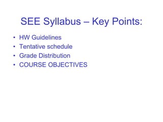
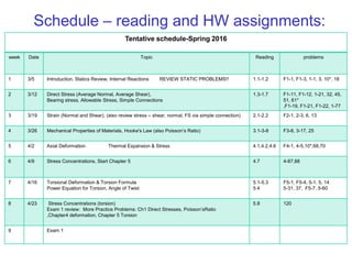
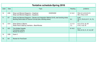
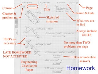
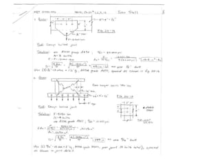
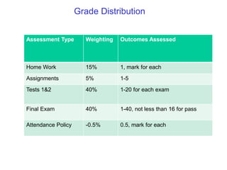
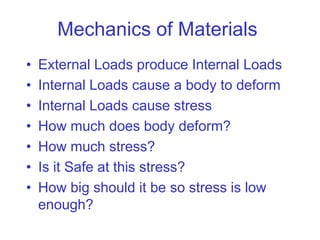
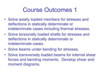


The document outlines the syllabus and structure of a strength of materials course taught by Dr. Hamed Abdulgader Dow, detailing the schedule, reading assignments, homework guidelines, and course objectives for Spring 2016. It covers fundamental concepts such as external loads, internal reactions, static equilibrium, stress analysis, and provides examples of free-body diagrams and internal force calculations. The document aims to prepare students for practical engineering applications while assessing their understanding through assignments and examinations.