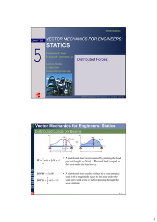
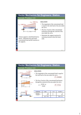
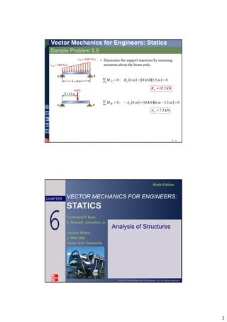
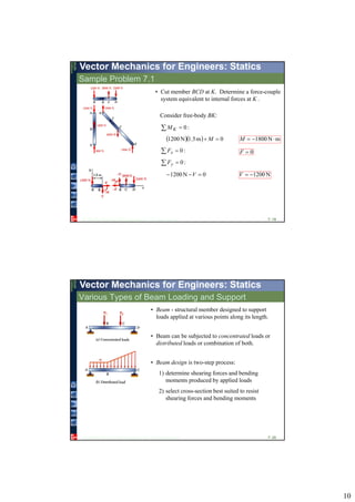
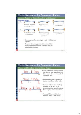
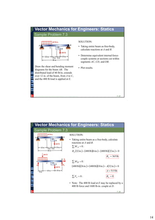
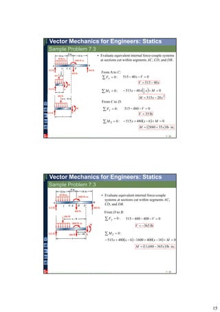
1
VECTOR MECHANICS FOR ENGINEERS:
STATICS
Ninth Edition
Ferdinand P. Beer
E. Russell Johnston, Jr.
Lecture Notes:
J. Walt Oler
Texas Tech University
CHAPTER
© 2010 The McGraw-Hill Companies, Inc. All rights reserved.
Distributed Forces:5
© 2010The McGraw-Hill Companies, Inc. All rights reserved.
Vector Mechanics for Engineers: Statics
Ninth
Edition
Distributed Loads on Beams
5 - 2
• A distributed load is represented by plotting the load
per unit length, w (N/m) . The total load is equal to
the area under the load curve.
  AdAdxwW
L
0
 
  AxdAxAOP
dWxWOP
L




0
• A distributed load can be replace by a concentrated
load with a magnitude equal to the area under the
load curve and a line of action passing through the
area centroid.
2
© 2010The McGraw-Hill Companies, Inc. All rights reserved.
Vector Mechanics for Engineers: StaticsNinth
Edition
Sample Problem 5.9
5 - 3
A beam supports a distributed load as
shown. Determine the equivalent
concentrated load and the reactions at
the supports.
SOLUTION:
• The magnitude of the concentrated load
is equal to the total load or the area under
the curve.
• The line of action of the concentrated
load passes through the centroid of the
area under the curve.
• Determine the support reactions by
summing moments about the beam
ends.
© 2010The McGraw-Hill Companies, Inc. All rights reserved.
Vector Mechanics for Engineers: Statics
Ninth
Edition
Sample Problem 5.9
5 - 4
SOLUTION:
• The magnitude of the concentrated load is equal to
the total load or the area under the curve.
kN0.18F
• The line of action of the concentrated load passes
through the centroid of the area under the curve.
kN18
mkN63 
X m5.3X
3
© 2010The McGraw-Hill Companies, Inc. All rights reserved.
Vector Mechanics for Engineers: StaticsNinth
Edition
Sample Problem 5.9
5 - 5
• Determine the support reactions by summing
moments about the beam ends.
     0m.53kN18m6:0  yA BM
kN5.10yB
     0m.53m6kN18m6:0  yB AM
kN5.7yA
VECTOR MECHANICS FOR ENGINEERS:
STATICS
Ninth Edition
Ferdinand P. Beer
E. Russell Johnston, Jr.
Lecture Notes:
J. Walt Oler
Texas Tech University
CHAPTER
© 2010 The McGraw-Hill Companies, Inc. All rights reserved.
Analysis of Structures6
4
© 2010The McGraw-Hill Companies, Inc. All rights reserved.
Vector Mechanics for Engineers: StaticsNinth
Edition
Analysis of Frames
6 - 7
• Frames and machines are structures with at least one
multiforce member. Frames are designed to support loads
and are usually stationary. Machines contain moving parts
and are designed to transmit and modify forces.
• A free body diagram of the complete frame is used to
determine the external forces acting on the frame.
• Internal forces are determined by dismembering the frame
and creating free-body diagrams for each component.
• Forces between connected components are equal, have the
same line of action, and opposite sense.
• Forces on two force members have known lines of action
but unknown magnitude and sense.
• Forces on multiforce members have unknown magnitude
and line of action. They must be represented with two
unknown components.
© 2010The McGraw-Hill Companies, Inc. All rights reserved.
Vector Mechanics for Engineers: Statics
Ninth
Edition
Frames Which Cease To Be Rigid When Detached From Their Supports
6 - 8
• Some frames may collapse if removed from
their supports. Such frames can not be treated
as rigid bodies.
• A free-body diagram of the complete frame
indicates four unknown force components which
can not be determined from the three equilibrium
conditions.
• The frame must be considered as two distinct, but
related, rigid bodies.
• With equal and opposite reactions at the contact
point between members, the two free-body
diagrams indicate 6 unknown force components.
• Equilibrium requirements for the two rigid
bodies yield 6 independent equations.
5
© 2010The McGraw-Hill Companies, Inc. All rights reserved.
Vector Mechanics for Engineers: StaticsNinth
Edition
Sample Problem 6.4
6 - 9
Members ACE and BCD are
connected by a pin at C and by the
link DE. For the loading shown,
determine the force in link DE and the
components of the force exerted at C
on member BCD.
SOLUTION:
• Create a free-body diagram for the
complete frame and solve for the support
reactions.
• Define a free-body diagram for member
BCD. The force exerted by the link DE
has a known line of action but unknown
magnitude. It is determined by summing
moments about C.
• With the force on the link DE known, the
sum of forces in the x and y directions
may be used to find the force
components at C.
• With member ACE as a free-body,
check the solution by summing
moments about A.
© 2010The McGraw-Hill Companies, Inc. All rights reserved.
Vector Mechanics for Engineers: Statics
Ninth
Edition
Sample Problem 6.4
6 - 10
SOLUTION:
• Create a free-body diagram for the complete frame
and solve for the support reactions.
N4800  yy AF  N480yA
    mm160mm100N4800 BM A 
 N300B
xx ABF  0  N300xA
 
07.28tan 150
801

Note:
6
© 2010The McGraw-Hill Companies, Inc. All rights reserved.
Vector Mechanics for Engineers: StaticsNinth
Edition
Sample Problem 6.4
6 - 11
• Define a free-body diagram for member
BCD. The force exerted by the link DE has a
known line of action but unknown
magnitude. It is determined by summing
moments about C.
        
N561
mm100N480mm06N300mm250sin0


DE
DEC
F
FM 
CFDE N561
• Sum of forces in the x and y directions may be used to find the force
components at C.
  N300cosN5610
N300cos0




x
DExx
C
FCF
N795xC
  N480sinN5610
N480sin0




y
DEyy
C
FCF
N216yC
© 2010The McGraw-Hill Companies, Inc. All rights reserved.
Vector Mechanics for Engineers: Statics
Ninth
Edition
Sample Problem 6.4
6 - 12
• With member ACE as a free-body, check
the solution by summing moments about A.
       
         0mm220795mm100sin561mm300cos561
mm220mm100sinmm300cos



 xDEDEA CFFM
(checks)
7
VECTOR MECHANICS FOR ENGINEERS:
STATICS
Ninth Edition
Ferdinand P. Beer
E. Russell Johnston, Jr.
Lecture Notes:
J. Walt Oler
Texas Tech University
CHAPTER
© 2010 The McGraw-Hill Companies, Inc. All rights reserved.
Forces in Beams and
Cables
7
© 2010The McGraw-Hill Companies, Inc. All rights reserved.
Vector Mechanics for Engineers: Statics
Ninth
Edition
Internal Forces in Members
7- 14
• Straight two-force member AB is in
equilibrium under application of F and
-F.
• Internal forces equivalent to F and -F are
required for equilibrium of free-bodies AC
and CB.
• Multiforce member ABCD is in equil-
ibrium under application of cable and
member contact forces.
• Internal forces equivalent to a force-
couple system are necessary for equil-
ibrium of free-bodies JD and ABCJ.
• An internal force-couple system is
required for equilibrium of two-force
members which are not straight.
8
© 2010The McGraw-Hill Companies, Inc. All rights reserved.
Vector Mechanics for Engineers: StaticsNinth
Edition
Sample Problem 7.1
7- 15
Determine the internal forces (a) in
member ACF at point J and (b) in
member BCD at K.
SOLUTION:
• Compute reactions and forces at
connections for each member.
• Cut member ACF at J. The internal
forces at J are represented by equivalent
force-couple system which is determined
by considering equilibrium of either part.
• Cut member BCD at K. Determine
force-couple system equivalent to
internal forces at K by applying
equilibrium conditions to either part.
© 2010The McGraw-Hill Companies, Inc. All rights reserved.
Vector Mechanics for Engineers: Statics
Ninth
Edition
Sample Problem 7.1
7- 16
:0 yF
0N1800N2400  yE NEy 600
:0 xF 0xE
SOLUTION:
• Compute reactions and connection forces.
:0 EM
     0m8.4m6.3N2400  F N1800F
Consider entire frame as a free-body:
9
© 2010The McGraw-Hill Companies, Inc. All rights reserved.
Vector Mechanics for Engineers: StaticsNinth
Edition
Sample Problem 7.1
7- 17
Consider member BCD as free-body:
:0 BM
     0m4.2m6.3N2400  yC N3600yC
:0 CM
     0m4.2m2.1N2400  yB N1200yB
:0 xF 0 xx CB
Consider member ABE as free-body:
:0 AM   0m4.2 xB 0xB
  :0xF 0 xx AB 0xA
  :0yF 0N600  yy BA N1800yA
From member BCD,
:0 xF 0 xx CB 0xC
© 2010The McGraw-Hill Companies, Inc. All rights reserved.
Vector Mechanics for Engineers: Statics
Ninth
Edition
Sample Problem 7.1
7- 18
• Cut member ACF at J. The internal forces at J are
represented by equivalent force-couple system.
Consider free-body AJ:
:0 JM
   0m2.1N1800  M mN2160 M
:0 xF
  07.41cosN1800 F N1344F
:0 yF
  07.41sinN1800 V N1197V
10
© 2010The McGraw-Hill Companies, Inc. All rights reserved.
Vector Mechanics for Engineers: StaticsNinth
Edition
Sample Problem 7.1
7- 19
• Cut member BCD at K. Determine a force-couple
system equivalent to internal forces at K .
Consider free-body BK:
:0 KM
   0m5.1N1200  M mN1800 M
:0 xF 0F
:0 yF
0N1200  V N1200V
© 2010The McGraw-Hill Companies, Inc. All rights reserved.
Vector Mechanics for Engineers: Statics
Ninth
Edition
Various Types of Beam Loading and Support
7- 20
• Beam - structural member designed to support
loads applied at various points along its length.
• Beam design is two-step process:
1) determine shearing forces and bending
moments produced by applied loads
2) select cross-section best suited to resist
shearing forces and bending moments
• Beam can be subjected to concentrated loads or
distributed loads or combination of both.
11
© 2010The McGraw-Hill Companies, Inc. All rights reserved.
Vector Mechanics for Engineers: StaticsNinth
Edition
Various Types of Beam Loading and Support
7- 21
• Beams are classified according to way in which they are
supported.
• Reactions at beam supports are determinate if they
involve only three unknowns. Otherwise, they are
statically indeterminate.
© 2010The McGraw-Hill Companies, Inc. All rights reserved.
Vector Mechanics for Engineers: Statics
Ninth
Edition
Shear and Bending Moment in a Beam
7- 22
• Wish to determine bending moment
and shearing force at any point in a
beam subjected to concentrated and
distributed loads.
• Determine reactions at supports by
treating whole beam as free-body.
• Cut beam at C and draw free-body
diagrams for AC and CB. By
definition, positive sense for internal
force-couple systems are as shown.
• From equilibrium considerations,
determine M and V or M’ and V’.
12
© 2010The McGraw-Hill Companies, Inc. All rights reserved.
Vector Mechanics for Engineers: StaticsNinth
Edition
Shear and Bending Moment Diagrams
7- 23
• Variation of shear and bending
moment along beam may be
plotted.
• Determine reactions at
supports.
• Cut beam at C and consider
member AC,
22 PxMPV 
• Cut beam at E and consider
member EB,
  22 xLPMPV 
• For a beam subjected to
concentrated loads, shear is
constant between loading points
and moment varies linearly.
© 2010The McGraw-Hill Companies, Inc. All rights reserved.
Vector Mechanics for Engineers: Statics
Ninth
Edition
Sample Problem 7.2
7- 24
Draw the shear and bending moment
diagrams for the beam and loading
shown.
SOLUTION:
• Taking entire beam as a free-body,
calculate reactions at B and D.
• Find equivalent internal force-couple
systems for free-bodies formed by
cutting beam on either side of load
application points.
• Plot results.
13
© 2010The McGraw-Hill Companies, Inc. All rights reserved.
Vector Mechanics for Engineers: StaticsNinth
Edition
Sample Problem 7.2
7- 25
SOLUTION:
• Taking entire beam as a free-body, calculate
reactions at B and D.
• Find equivalent internal force-couple systems at
sections on either side of load application points.
  :0yF 0kN20 1  V kN201 V
:02 M    0m0kN20 1  M 01 M
mkN50kN26
mkN50kN26
mkN50kN26
mkN50kN26
66
55
44
33




MV
MV
MV
MV
Similarly,
© 2010The McGraw-Hill Companies, Inc. All rights reserved.
Vector Mechanics for Engineers: Statics
Ninth
Edition
Sample Problem 7.2
7- 26
• Plot results.
Note that shear is of constant value
between concentrated loads and
bending moment varies linearly.
14
© 2010The McGraw-Hill Companies, Inc. All rights reserved.
Vector Mechanics for Engineers: StaticsNinth
Edition
Sample Problem 7.3
7- 27
Draw the shear and bending moment
diagrams for the beam AB. The
distributed load of 40 lb/in. extends
over 12 in. of the beam, from A to C,
and the 400 lb load is applied at E.
SOLUTION:
• Taking entire beam as free-body,
calculate reactions at A and B.
• Determine equivalent internal force-
couple systems at sections cut within
segments AC, CD, and DB.
• Plot results.
© 2010The McGraw-Hill Companies, Inc. All rights reserved.
Vector Mechanics for Engineers: Statics
Ninth
Edition
Sample Problem 7.3
7- 28
SOLUTION:
• Taking entire beam as a free-body, calculate
reactions at A and B.
:0 AM
        0in.22lb400in.6lb480in.32 yB
lb365yB
:0 BM
        0in.32in.10lb400in.26lb480  A
lb515A
:0 xF 0xB
• Note: The 400 lb load at E may be replaced by a
400 lb force and 1600 lb-in. couple at D.
15
© 2010The McGraw-Hill Companies, Inc. All rights reserved.
Vector Mechanics for Engineers: StaticsNinth
Edition
Sample Problem 7.3
7- 29
:01 M   040515 2
1  Mxxx
2
20515 xxM 
:02 M   06480515  Mxx
  in.lb352880  xM
From C to D:
  :0yF 0480515  V
lb35V
• Evaluate equivalent internal force-couple systems
at sections cut within segments AC, CD, and DB.
From A to C:
  :0yF 040515  Vx
xV 40515
© 2010The McGraw-Hill Companies, Inc. All rights reserved.
Vector Mechanics for Engineers: Statics
Ninth
Edition
Sample Problem 7.3
7- 30
:02 M
    01840016006480515  Mxxx
  in.lb365680,11  xM
• Evaluate equivalent internal force-couple
systems at sections cut within segments AC,
CD, and DB.
From D to B:
  :0yF 0400480515  V
lb365V
16
© 2010The McGraw-Hill Companies, Inc. All rights reserved.
Vector Mechanics for Engineers: StaticsNinth
Edition
Sample Problem 7.3
7- 31
• Plot results.
From A to C:
xV 40515
2
20515 xxM 
From C to D:
lb35V
  in.lb352880  xM
From D to B:
lb365V
  in.lb365680,11  xM
© 2010The McGraw-Hill Companies, Inc. All rights reserved.
Vector Mechanics for Engineers: Statics
Ninth
Edition
Relations Among Load, Shear, and Bending Moment
7- 32
• Relations between load and shear:
 
w
x
V
dx
dV
xwVVV
x





 0
lim
0
 curveloadunderarea 
D
C
x
x
CD dxwVV
• Relations between shear and bending moment:
 
  VxwV
x
M
dx
dM
x
xwxVMMM
xx







 2
1
00
limlim
0
2
 curveshearunderarea 
D
C
x
x
CD dxVMM
17
© 2010The McGraw-Hill Companies, Inc. All rights reserved.
Vector Mechanics for Engineers: StaticsNinth
Edition
Relations Among Load, Shear, and Bending Moment
7- 33
• Reactions at supports,
2
wL
RR BA 
• Shear curve,







 
x
L
wwx
wL
wxVV
wxdxwVV
A
x
A
22
0
• Moment curve,
 

















0at
8
22
2
max
2
0
0
V
dx
dM
M
wL
M
xxL
w
dxx
L
wM
VdxMM
x
x
A

00 statics review

  • 1.
    1 VECTOR MECHANICS FORENGINEERS: STATICS Ninth Edition Ferdinand P. Beer E. Russell Johnston, Jr. Lecture Notes: J. Walt Oler Texas Tech University CHAPTER © 2010 The McGraw-Hill Companies, Inc. All rights reserved. Distributed Forces:5 © 2010The McGraw-Hill Companies, Inc. All rights reserved. Vector Mechanics for Engineers: Statics Ninth Edition Distributed Loads on Beams 5 - 2 • A distributed load is represented by plotting the load per unit length, w (N/m) . The total load is equal to the area under the load curve.   AdAdxwW L 0     AxdAxAOP dWxWOP L     0 • A distributed load can be replace by a concentrated load with a magnitude equal to the area under the load curve and a line of action passing through the area centroid.
  • 2.
    2 © 2010The McGraw-HillCompanies, Inc. All rights reserved. Vector Mechanics for Engineers: StaticsNinth Edition Sample Problem 5.9 5 - 3 A beam supports a distributed load as shown. Determine the equivalent concentrated load and the reactions at the supports. SOLUTION: • The magnitude of the concentrated load is equal to the total load or the area under the curve. • The line of action of the concentrated load passes through the centroid of the area under the curve. • Determine the support reactions by summing moments about the beam ends. © 2010The McGraw-Hill Companies, Inc. All rights reserved. Vector Mechanics for Engineers: Statics Ninth Edition Sample Problem 5.9 5 - 4 SOLUTION: • The magnitude of the concentrated load is equal to the total load or the area under the curve. kN0.18F • The line of action of the concentrated load passes through the centroid of the area under the curve. kN18 mkN63  X m5.3X
  • 3.
    3 © 2010The McGraw-HillCompanies, Inc. All rights reserved. Vector Mechanics for Engineers: StaticsNinth Edition Sample Problem 5.9 5 - 5 • Determine the support reactions by summing moments about the beam ends.      0m.53kN18m6:0  yA BM kN5.10yB      0m.53m6kN18m6:0  yB AM kN5.7yA VECTOR MECHANICS FOR ENGINEERS: STATICS Ninth Edition Ferdinand P. Beer E. Russell Johnston, Jr. Lecture Notes: J. Walt Oler Texas Tech University CHAPTER © 2010 The McGraw-Hill Companies, Inc. All rights reserved. Analysis of Structures6
  • 4.
    4 © 2010The McGraw-HillCompanies, Inc. All rights reserved. Vector Mechanics for Engineers: StaticsNinth Edition Analysis of Frames 6 - 7 • Frames and machines are structures with at least one multiforce member. Frames are designed to support loads and are usually stationary. Machines contain moving parts and are designed to transmit and modify forces. • A free body diagram of the complete frame is used to determine the external forces acting on the frame. • Internal forces are determined by dismembering the frame and creating free-body diagrams for each component. • Forces between connected components are equal, have the same line of action, and opposite sense. • Forces on two force members have known lines of action but unknown magnitude and sense. • Forces on multiforce members have unknown magnitude and line of action. They must be represented with two unknown components. © 2010The McGraw-Hill Companies, Inc. All rights reserved. Vector Mechanics for Engineers: Statics Ninth Edition Frames Which Cease To Be Rigid When Detached From Their Supports 6 - 8 • Some frames may collapse if removed from their supports. Such frames can not be treated as rigid bodies. • A free-body diagram of the complete frame indicates four unknown force components which can not be determined from the three equilibrium conditions. • The frame must be considered as two distinct, but related, rigid bodies. • With equal and opposite reactions at the contact point between members, the two free-body diagrams indicate 6 unknown force components. • Equilibrium requirements for the two rigid bodies yield 6 independent equations.
  • 5.
    5 © 2010The McGraw-HillCompanies, Inc. All rights reserved. Vector Mechanics for Engineers: StaticsNinth Edition Sample Problem 6.4 6 - 9 Members ACE and BCD are connected by a pin at C and by the link DE. For the loading shown, determine the force in link DE and the components of the force exerted at C on member BCD. SOLUTION: • Create a free-body diagram for the complete frame and solve for the support reactions. • Define a free-body diagram for member BCD. The force exerted by the link DE has a known line of action but unknown magnitude. It is determined by summing moments about C. • With the force on the link DE known, the sum of forces in the x and y directions may be used to find the force components at C. • With member ACE as a free-body, check the solution by summing moments about A. © 2010The McGraw-Hill Companies, Inc. All rights reserved. Vector Mechanics for Engineers: Statics Ninth Edition Sample Problem 6.4 6 - 10 SOLUTION: • Create a free-body diagram for the complete frame and solve for the support reactions. N4800  yy AF  N480yA     mm160mm100N4800 BM A   N300B xx ABF  0  N300xA   07.28tan 150 801  Note:
  • 6.
    6 © 2010The McGraw-HillCompanies, Inc. All rights reserved. Vector Mechanics for Engineers: StaticsNinth Edition Sample Problem 6.4 6 - 11 • Define a free-body diagram for member BCD. The force exerted by the link DE has a known line of action but unknown magnitude. It is determined by summing moments about C.          N561 mm100N480mm06N300mm250sin0   DE DEC F FM  CFDE N561 • Sum of forces in the x and y directions may be used to find the force components at C.   N300cosN5610 N300cos0     x DExx C FCF N795xC   N480sinN5610 N480sin0     y DEyy C FCF N216yC © 2010The McGraw-Hill Companies, Inc. All rights reserved. Vector Mechanics for Engineers: Statics Ninth Edition Sample Problem 6.4 6 - 12 • With member ACE as a free-body, check the solution by summing moments about A.                  0mm220795mm100sin561mm300cos561 mm220mm100sinmm300cos     xDEDEA CFFM (checks)
  • 7.
    7 VECTOR MECHANICS FORENGINEERS: STATICS Ninth Edition Ferdinand P. Beer E. Russell Johnston, Jr. Lecture Notes: J. Walt Oler Texas Tech University CHAPTER © 2010 The McGraw-Hill Companies, Inc. All rights reserved. Forces in Beams and Cables 7 © 2010The McGraw-Hill Companies, Inc. All rights reserved. Vector Mechanics for Engineers: Statics Ninth Edition Internal Forces in Members 7- 14 • Straight two-force member AB is in equilibrium under application of F and -F. • Internal forces equivalent to F and -F are required for equilibrium of free-bodies AC and CB. • Multiforce member ABCD is in equil- ibrium under application of cable and member contact forces. • Internal forces equivalent to a force- couple system are necessary for equil- ibrium of free-bodies JD and ABCJ. • An internal force-couple system is required for equilibrium of two-force members which are not straight.
  • 8.
    8 © 2010The McGraw-HillCompanies, Inc. All rights reserved. Vector Mechanics for Engineers: StaticsNinth Edition Sample Problem 7.1 7- 15 Determine the internal forces (a) in member ACF at point J and (b) in member BCD at K. SOLUTION: • Compute reactions and forces at connections for each member. • Cut member ACF at J. The internal forces at J are represented by equivalent force-couple system which is determined by considering equilibrium of either part. • Cut member BCD at K. Determine force-couple system equivalent to internal forces at K by applying equilibrium conditions to either part. © 2010The McGraw-Hill Companies, Inc. All rights reserved. Vector Mechanics for Engineers: Statics Ninth Edition Sample Problem 7.1 7- 16 :0 yF 0N1800N2400  yE NEy 600 :0 xF 0xE SOLUTION: • Compute reactions and connection forces. :0 EM      0m8.4m6.3N2400  F N1800F Consider entire frame as a free-body:
  • 9.
    9 © 2010The McGraw-HillCompanies, Inc. All rights reserved. Vector Mechanics for Engineers: StaticsNinth Edition Sample Problem 7.1 7- 17 Consider member BCD as free-body: :0 BM      0m4.2m6.3N2400  yC N3600yC :0 CM      0m4.2m2.1N2400  yB N1200yB :0 xF 0 xx CB Consider member ABE as free-body: :0 AM   0m4.2 xB 0xB   :0xF 0 xx AB 0xA   :0yF 0N600  yy BA N1800yA From member BCD, :0 xF 0 xx CB 0xC © 2010The McGraw-Hill Companies, Inc. All rights reserved. Vector Mechanics for Engineers: Statics Ninth Edition Sample Problem 7.1 7- 18 • Cut member ACF at J. The internal forces at J are represented by equivalent force-couple system. Consider free-body AJ: :0 JM    0m2.1N1800  M mN2160 M :0 xF   07.41cosN1800 F N1344F :0 yF   07.41sinN1800 V N1197V
  • 10.
    10 © 2010The McGraw-HillCompanies, Inc. All rights reserved. Vector Mechanics for Engineers: StaticsNinth Edition Sample Problem 7.1 7- 19 • Cut member BCD at K. Determine a force-couple system equivalent to internal forces at K . Consider free-body BK: :0 KM    0m5.1N1200  M mN1800 M :0 xF 0F :0 yF 0N1200  V N1200V © 2010The McGraw-Hill Companies, Inc. All rights reserved. Vector Mechanics for Engineers: Statics Ninth Edition Various Types of Beam Loading and Support 7- 20 • Beam - structural member designed to support loads applied at various points along its length. • Beam design is two-step process: 1) determine shearing forces and bending moments produced by applied loads 2) select cross-section best suited to resist shearing forces and bending moments • Beam can be subjected to concentrated loads or distributed loads or combination of both.
  • 11.
    11 © 2010The McGraw-HillCompanies, Inc. All rights reserved. Vector Mechanics for Engineers: StaticsNinth Edition Various Types of Beam Loading and Support 7- 21 • Beams are classified according to way in which they are supported. • Reactions at beam supports are determinate if they involve only three unknowns. Otherwise, they are statically indeterminate. © 2010The McGraw-Hill Companies, Inc. All rights reserved. Vector Mechanics for Engineers: Statics Ninth Edition Shear and Bending Moment in a Beam 7- 22 • Wish to determine bending moment and shearing force at any point in a beam subjected to concentrated and distributed loads. • Determine reactions at supports by treating whole beam as free-body. • Cut beam at C and draw free-body diagrams for AC and CB. By definition, positive sense for internal force-couple systems are as shown. • From equilibrium considerations, determine M and V or M’ and V’.
  • 12.
    12 © 2010The McGraw-HillCompanies, Inc. All rights reserved. Vector Mechanics for Engineers: StaticsNinth Edition Shear and Bending Moment Diagrams 7- 23 • Variation of shear and bending moment along beam may be plotted. • Determine reactions at supports. • Cut beam at C and consider member AC, 22 PxMPV  • Cut beam at E and consider member EB,   22 xLPMPV  • For a beam subjected to concentrated loads, shear is constant between loading points and moment varies linearly. © 2010The McGraw-Hill Companies, Inc. All rights reserved. Vector Mechanics for Engineers: Statics Ninth Edition Sample Problem 7.2 7- 24 Draw the shear and bending moment diagrams for the beam and loading shown. SOLUTION: • Taking entire beam as a free-body, calculate reactions at B and D. • Find equivalent internal force-couple systems for free-bodies formed by cutting beam on either side of load application points. • Plot results.
  • 13.
    13 © 2010The McGraw-HillCompanies, Inc. All rights reserved. Vector Mechanics for Engineers: StaticsNinth Edition Sample Problem 7.2 7- 25 SOLUTION: • Taking entire beam as a free-body, calculate reactions at B and D. • Find equivalent internal force-couple systems at sections on either side of load application points.   :0yF 0kN20 1  V kN201 V :02 M    0m0kN20 1  M 01 M mkN50kN26 mkN50kN26 mkN50kN26 mkN50kN26 66 55 44 33     MV MV MV MV Similarly, © 2010The McGraw-Hill Companies, Inc. All rights reserved. Vector Mechanics for Engineers: Statics Ninth Edition Sample Problem 7.2 7- 26 • Plot results. Note that shear is of constant value between concentrated loads and bending moment varies linearly.
  • 14.
    14 © 2010The McGraw-HillCompanies, Inc. All rights reserved. Vector Mechanics for Engineers: StaticsNinth Edition Sample Problem 7.3 7- 27 Draw the shear and bending moment diagrams for the beam AB. The distributed load of 40 lb/in. extends over 12 in. of the beam, from A to C, and the 400 lb load is applied at E. SOLUTION: • Taking entire beam as free-body, calculate reactions at A and B. • Determine equivalent internal force- couple systems at sections cut within segments AC, CD, and DB. • Plot results. © 2010The McGraw-Hill Companies, Inc. All rights reserved. Vector Mechanics for Engineers: Statics Ninth Edition Sample Problem 7.3 7- 28 SOLUTION: • Taking entire beam as a free-body, calculate reactions at A and B. :0 AM         0in.22lb400in.6lb480in.32 yB lb365yB :0 BM         0in.32in.10lb400in.26lb480  A lb515A :0 xF 0xB • Note: The 400 lb load at E may be replaced by a 400 lb force and 1600 lb-in. couple at D.
  • 15.
    15 © 2010The McGraw-HillCompanies, Inc. All rights reserved. Vector Mechanics for Engineers: StaticsNinth Edition Sample Problem 7.3 7- 29 :01 M   040515 2 1  Mxxx 2 20515 xxM  :02 M   06480515  Mxx   in.lb352880  xM From C to D:   :0yF 0480515  V lb35V • Evaluate equivalent internal force-couple systems at sections cut within segments AC, CD, and DB. From A to C:   :0yF 040515  Vx xV 40515 © 2010The McGraw-Hill Companies, Inc. All rights reserved. Vector Mechanics for Engineers: Statics Ninth Edition Sample Problem 7.3 7- 30 :02 M     01840016006480515  Mxxx   in.lb365680,11  xM • Evaluate equivalent internal force-couple systems at sections cut within segments AC, CD, and DB. From D to B:   :0yF 0400480515  V lb365V
  • 16.
    16 © 2010The McGraw-HillCompanies, Inc. All rights reserved. Vector Mechanics for Engineers: StaticsNinth Edition Sample Problem 7.3 7- 31 • Plot results. From A to C: xV 40515 2 20515 xxM  From C to D: lb35V   in.lb352880  xM From D to B: lb365V   in.lb365680,11  xM © 2010The McGraw-Hill Companies, Inc. All rights reserved. Vector Mechanics for Engineers: Statics Ninth Edition Relations Among Load, Shear, and Bending Moment 7- 32 • Relations between load and shear:   w x V dx dV xwVVV x       0 lim 0  curveloadunderarea  D C x x CD dxwVV • Relations between shear and bending moment:     VxwV x M dx dM x xwxVMMM xx         2 1 00 limlim 0 2  curveshearunderarea  D C x x CD dxVMM
  • 17.
    17 © 2010The McGraw-HillCompanies, Inc. All rights reserved. Vector Mechanics for Engineers: StaticsNinth Edition Relations Among Load, Shear, and Bending Moment 7- 33 • Reactions at supports, 2 wL RR BA  • Shear curve,          x L wwx wL wxVV wxdxwVV A x A 22 0 • Moment curve,                    0at 8 22 2 max 2 0 0 V dx dM M wL M xxL w dxx L wM VdxMM x x A