Download as PDF, PPTX

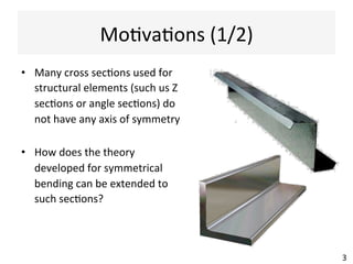
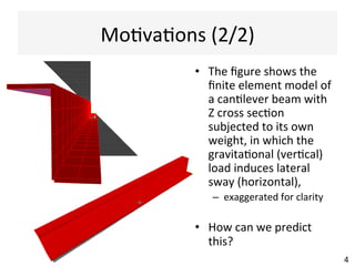
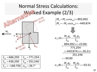
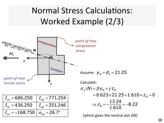
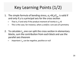

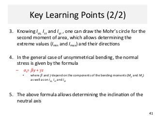

The document outlines a teaching schedule and key concepts related to unsymmetrical bending in structural mechanics, including methods for analyzing shear stresses and principal moments for asymmetric sections. It discusses the theoretical extension of symmetric bending theory to unsymmetrical cases, as well as tools like the Mohr's circle for stress analysis. Learning outcomes include determining principal directional moments and evaluating normal stresses in beams under unsymmetric bending conditions.