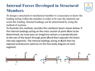
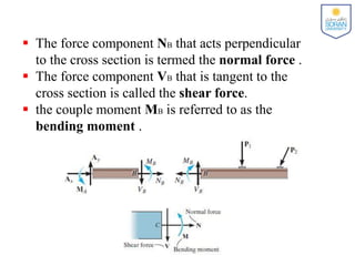
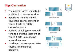
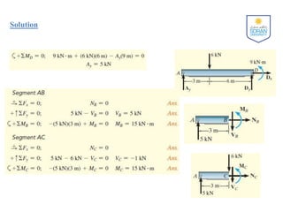
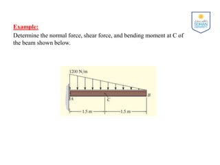
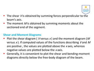
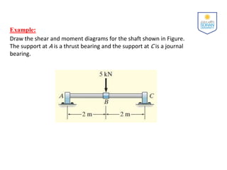
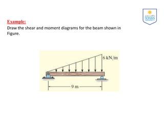
Engineering Mechanics
Statics
Soran University
Faculty of Engineering
Civil Engineering Department
Yousif J. Bas
(2022-2023)
CHAPTER OBJECTIVES
 To show how to use the method of sections to determine the
internal loadings in a member.
 To generalize this procedure by formulating equations that can
be plotted so that they describe the internal shear and moment
throughout a member.
Expected Outcomes
Able to determine the internal loadings.
Internal Forces
Hibbeler R. C., Engineering Mechanics , Statics, 13th edition, 2013
Chapter Outline
 Internal Forces Developed in Structural Members
 Shear and Moment Equations and Diagrams
Internal Forces Developed in Structural
Members
To design a structural or mechanical member it is necessary to know the
loading acting within the member in order to be sure the material can
resist this loading. Internal loadings can be determined by using the
method of sections .
To illustrate this method, consider the cantilever beam shown below. If
the internal loadings acting on the cross section at point B are to be
determined, we must pass an imaginary section a–a perpendicular
to the axis of the beam through point B and then separate the beam
into two segments. The internal loadings acting at B will then be
exposed and become external on the free-body diagram of each
segment.
 The force component NB that acts perpendicular
to the cross section is termed the normal force .
 The force component VB that is tangent to the
cross section is called the shear force.
 the couple moment MB is referred to as the
bending moment .
Sign Convention
 The normal force is said to be
positive if it creates tension.
 a positive shear force will
cause the beam segment on
which it acts to rotate
clockwise, and a
 positive bending moment will
tend to bend the segment on
which it acts in a concave
upward manner.
 Loadings that are opposite to
these are considered
negative.
Procedure for Analysis
Support Reactions.
 Before the member is sectioned, it may first be necessary to
determine its support reactions. Once obtained, the equilibrium
equations can then be used to solve for the internal loadings
after the member is sectioned.
Free-Body Diagram.
 It is important to keep all distributed loadings, couple moments,
and forces acting on the member in their exact locations , then
pass an imaginary section through the member, perpendicular
to its axis at the point where the internal loadings are to be
determined.
 After the section is made, draw a free-body diagram of the
segment that has the least number of loads on it, and indicate
the components of the internal force and couple moment
resultants at the cross section acting in their positive directions
in accordance with the established sign convention.
Procedure for Analysis
Equations of Equilibrium
 Moments should be summed at the section. This way the
normal and shear forces at the section are eliminated, and we
can obtain a direct solution for the moment.
 If the solution of the equilibrium equations yields a negative
scalar, the sense of the quantity is opposite to that shown on
the free-body diagram.
Example:
Determine the normal force, shear force, and bending moment acting
just to the left, point B , and just to the right, point C , of the 6-kN force
on the beam shown below.
Solution
Example:
Determine the normal force, shear force, and bending moment at C of
the beam shown below.
Solution:
Shear and Moment Equations and
Diagrams
Beams are structural members designed to support loadings applied
perpendicular to their axes. In general, they are long and straight and have a
constant cross-sectional area. They are often classified as to how they are
supported. For example, a simply supported beam is pinned at one end and
roller supported at the other, whereas a cantilevered beam is fixed at one
end and free at the other. The actual design of a beam requires a detailed
knowledge of the variation of the internal shear force V and bending
moment M acting at each point along the axis of the beam. These variations
of V and M along the beam’s axis can be obtained by using the method of
sections. In this case, however, it is necessary to section the beam at an
arbitrary distance x from one end and then apply the equations of
equilibrium to the segment having the length x . Doing this we can then
obtain V and M as functions of x .
Shear and Moment Equations and
Diagrams
In general, the internal shear and bending-moment functions will be
discontinuous, or their slopes will be discontinuous, at points where a distributed
load changes or where concentrated forces or couple moments are applied.
Because of this, these functions must be determined for each segment of the
beam located between any two discontinuities of loading. For example, segments
having lengths x1, x2, and x3 will have to be used to describe the variation of V
and M along the length of the beam in Fig. a . These functions will be valid only
within regions from 0 to a for x1, from a to b for x2, and from b to L for x3. If the
resulting functions of x are plotted, the graphs are termed the shear diagram and
bending-moment diagram , Fig. b and Fig. c , respectively.
Procedure for Analysis
Support Reactions
 Determine all the reactive forces and couple
moments acting on the beam and resolve all the
forces into components acting perpendicular and
parallel to the beam’s axis.
Shear and Moment Functions
 Specify separate coordinates x having an origin at
the beam’s left end and extending to regions of
the beam between concentrated forces and/or
couple moments, or where the distributed loading
is continuous.
 Section the beam at each distance x and draw the
free-body diagram of one of the segments. Be sure
V and M are shown acting in their positive sense ,
in accordance with the sign convention given in
Figure.
 The shear V is obtained by summing forces perpendicular to the
beam’s axis.
 The moment M is obtained by summing moments about the
sectioned end of the segment.
Shear and Moment Diagrams
 Plot the shear diagram ( V versus x ) and the moment diagram (M
versus x ). If computed values of the functions describing V and M
are positive , the values are plotted above the x axis, whereas
negative values are plotted below the x axis.
 Generally, it is convenient to plot the shear and bending-moment
diagrams directly below the free-body diagram of the beam.
Example:
Draw the shear and moment diagrams for the shaft shown in Figure.
The support at A is a thrust bearing and the support at C is a journal
bearing.
Solution:
Solution:
Example:
Draw the shear and moment diagrams for the beam shown in
Figure.
Solution:
Solution:

6- Internal Forces.pdf

  • 1.
    Engineering Mechanics Statics Soran University Facultyof Engineering Civil Engineering Department Yousif J. Bas (2022-2023)
  • 2.
    CHAPTER OBJECTIVES  Toshow how to use the method of sections to determine the internal loadings in a member.  To generalize this procedure by formulating equations that can be plotted so that they describe the internal shear and moment throughout a member. Expected Outcomes Able to determine the internal loadings. Internal Forces Hibbeler R. C., Engineering Mechanics , Statics, 13th edition, 2013
  • 3.
    Chapter Outline  InternalForces Developed in Structural Members  Shear and Moment Equations and Diagrams
  • 4.
    Internal Forces Developedin Structural Members To design a structural or mechanical member it is necessary to know the loading acting within the member in order to be sure the material can resist this loading. Internal loadings can be determined by using the method of sections . To illustrate this method, consider the cantilever beam shown below. If the internal loadings acting on the cross section at point B are to be determined, we must pass an imaginary section a–a perpendicular to the axis of the beam through point B and then separate the beam into two segments. The internal loadings acting at B will then be exposed and become external on the free-body diagram of each segment.
  • 5.
     The forcecomponent NB that acts perpendicular to the cross section is termed the normal force .  The force component VB that is tangent to the cross section is called the shear force.  the couple moment MB is referred to as the bending moment .
  • 6.
    Sign Convention  Thenormal force is said to be positive if it creates tension.  a positive shear force will cause the beam segment on which it acts to rotate clockwise, and a  positive bending moment will tend to bend the segment on which it acts in a concave upward manner.  Loadings that are opposite to these are considered negative.
  • 7.
    Procedure for Analysis SupportReactions.  Before the member is sectioned, it may first be necessary to determine its support reactions. Once obtained, the equilibrium equations can then be used to solve for the internal loadings after the member is sectioned. Free-Body Diagram.  It is important to keep all distributed loadings, couple moments, and forces acting on the member in their exact locations , then pass an imaginary section through the member, perpendicular to its axis at the point where the internal loadings are to be determined.  After the section is made, draw a free-body diagram of the segment that has the least number of loads on it, and indicate the components of the internal force and couple moment resultants at the cross section acting in their positive directions in accordance with the established sign convention.
  • 8.
    Procedure for Analysis Equationsof Equilibrium  Moments should be summed at the section. This way the normal and shear forces at the section are eliminated, and we can obtain a direct solution for the moment.  If the solution of the equilibrium equations yields a negative scalar, the sense of the quantity is opposite to that shown on the free-body diagram.
  • 9.
    Example: Determine the normalforce, shear force, and bending moment acting just to the left, point B , and just to the right, point C , of the 6-kN force on the beam shown below.
  • 10.
  • 11.
    Example: Determine the normalforce, shear force, and bending moment at C of the beam shown below.
  • 12.
  • 13.
    Shear and MomentEquations and Diagrams Beams are structural members designed to support loadings applied perpendicular to their axes. In general, they are long and straight and have a constant cross-sectional area. They are often classified as to how they are supported. For example, a simply supported beam is pinned at one end and roller supported at the other, whereas a cantilevered beam is fixed at one end and free at the other. The actual design of a beam requires a detailed knowledge of the variation of the internal shear force V and bending moment M acting at each point along the axis of the beam. These variations of V and M along the beam’s axis can be obtained by using the method of sections. In this case, however, it is necessary to section the beam at an arbitrary distance x from one end and then apply the equations of equilibrium to the segment having the length x . Doing this we can then obtain V and M as functions of x .
  • 14.
    Shear and MomentEquations and Diagrams In general, the internal shear and bending-moment functions will be discontinuous, or their slopes will be discontinuous, at points where a distributed load changes or where concentrated forces or couple moments are applied. Because of this, these functions must be determined for each segment of the beam located between any two discontinuities of loading. For example, segments having lengths x1, x2, and x3 will have to be used to describe the variation of V and M along the length of the beam in Fig. a . These functions will be valid only within regions from 0 to a for x1, from a to b for x2, and from b to L for x3. If the resulting functions of x are plotted, the graphs are termed the shear diagram and bending-moment diagram , Fig. b and Fig. c , respectively.
  • 15.
    Procedure for Analysis SupportReactions  Determine all the reactive forces and couple moments acting on the beam and resolve all the forces into components acting perpendicular and parallel to the beam’s axis. Shear and Moment Functions  Specify separate coordinates x having an origin at the beam’s left end and extending to regions of the beam between concentrated forces and/or couple moments, or where the distributed loading is continuous.  Section the beam at each distance x and draw the free-body diagram of one of the segments. Be sure V and M are shown acting in their positive sense , in accordance with the sign convention given in Figure.
  • 16.
     The shearV is obtained by summing forces perpendicular to the beam’s axis.  The moment M is obtained by summing moments about the sectioned end of the segment. Shear and Moment Diagrams  Plot the shear diagram ( V versus x ) and the moment diagram (M versus x ). If computed values of the functions describing V and M are positive , the values are plotted above the x axis, whereas negative values are plotted below the x axis.  Generally, it is convenient to plot the shear and bending-moment diagrams directly below the free-body diagram of the beam.
  • 17.
    Example: Draw the shearand moment diagrams for the shaft shown in Figure. The support at A is a thrust bearing and the support at C is a journal bearing.
  • 18.
  • 19.
  • 20.
    Example: Draw the shearand moment diagrams for the beam shown in Figure.
  • 21.
  • 22.