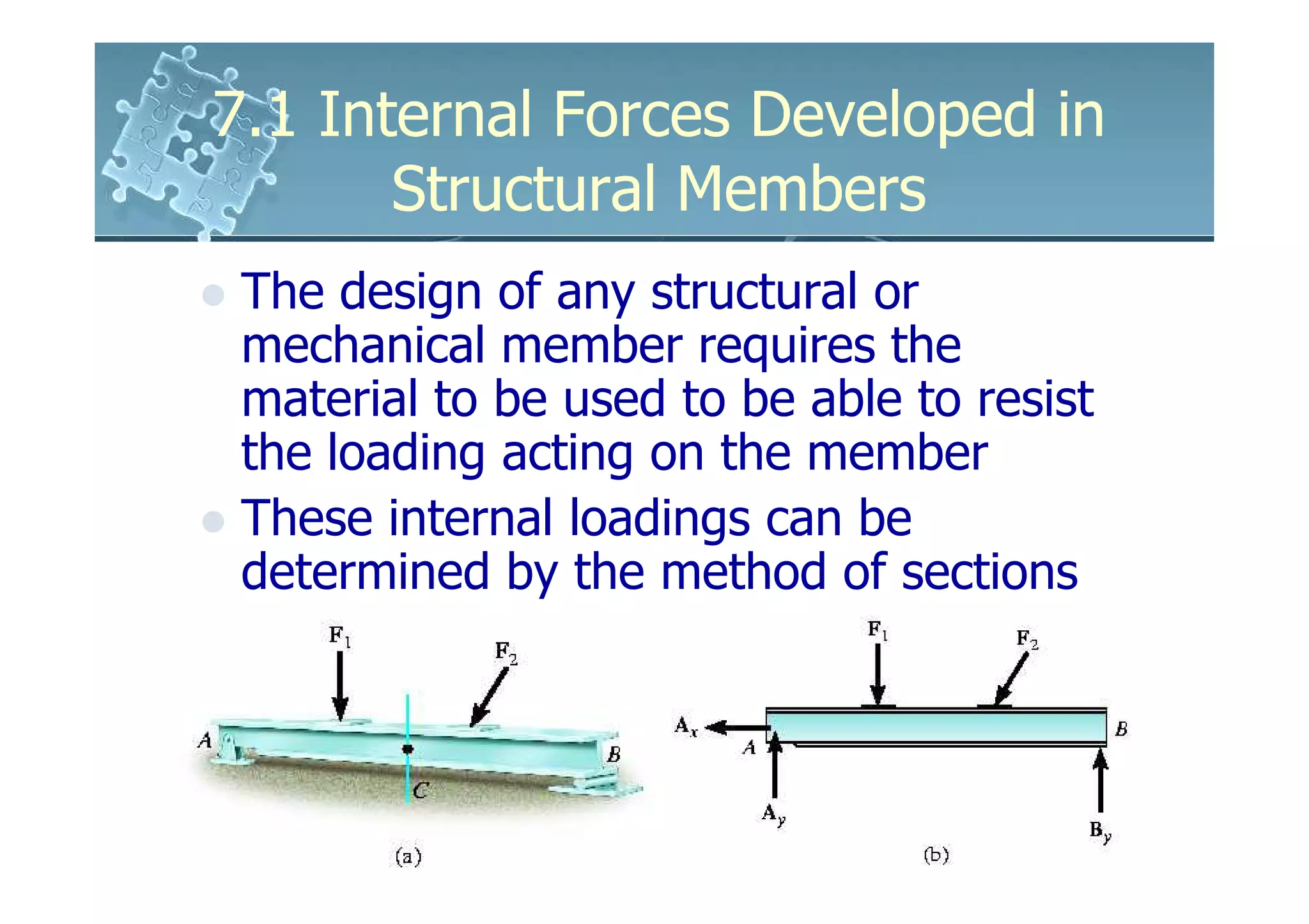
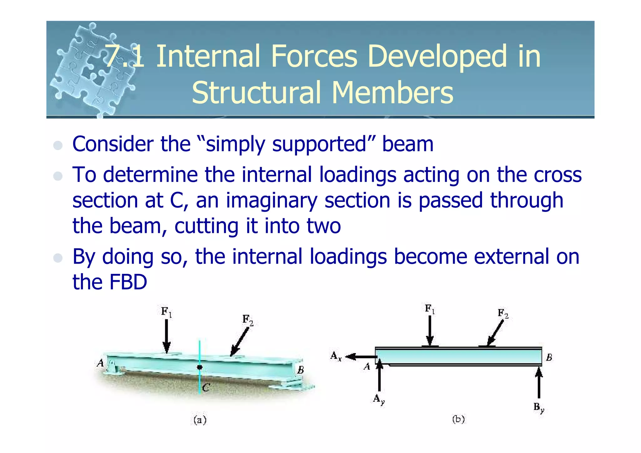
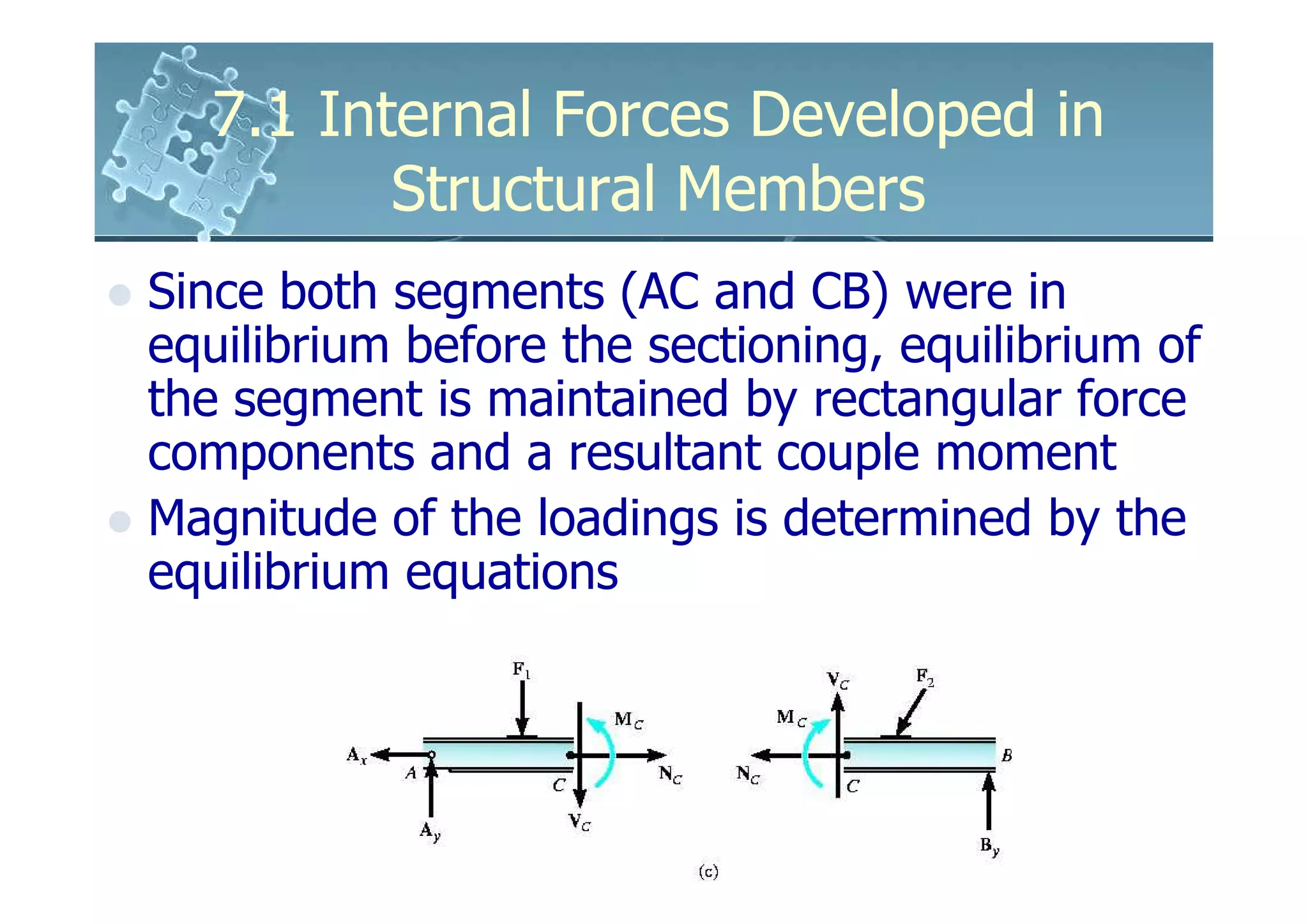
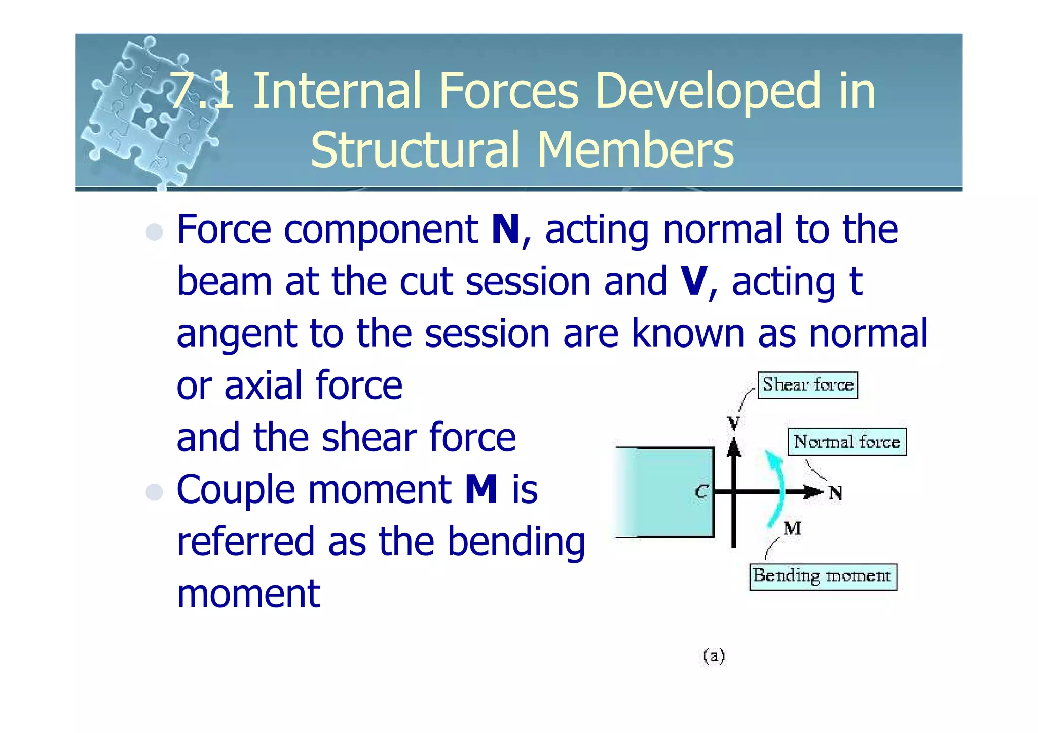
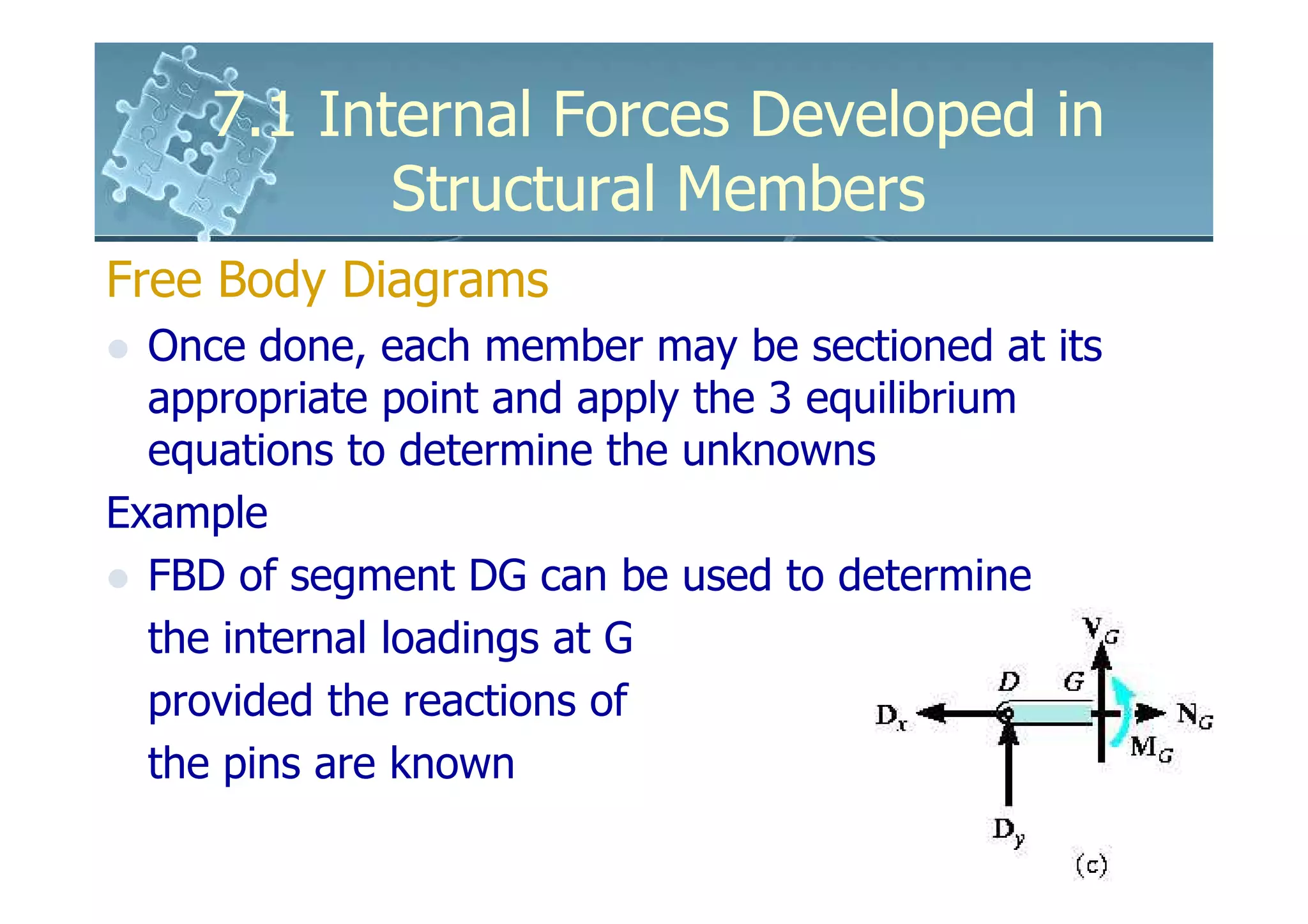
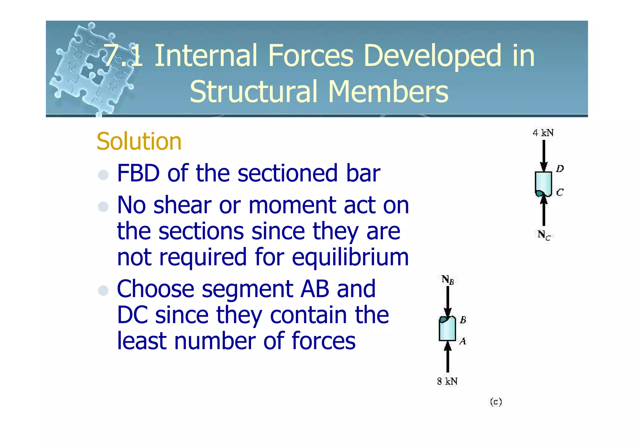
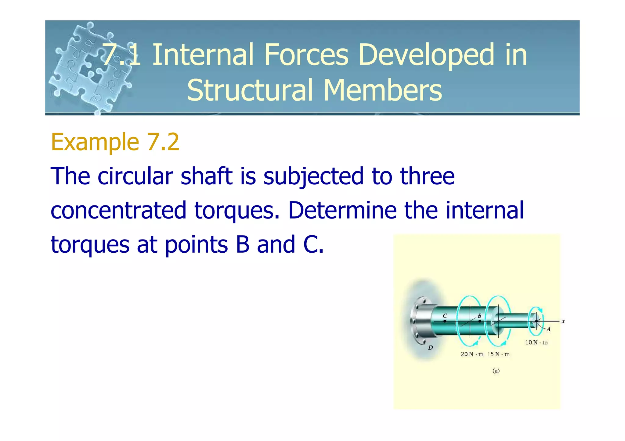
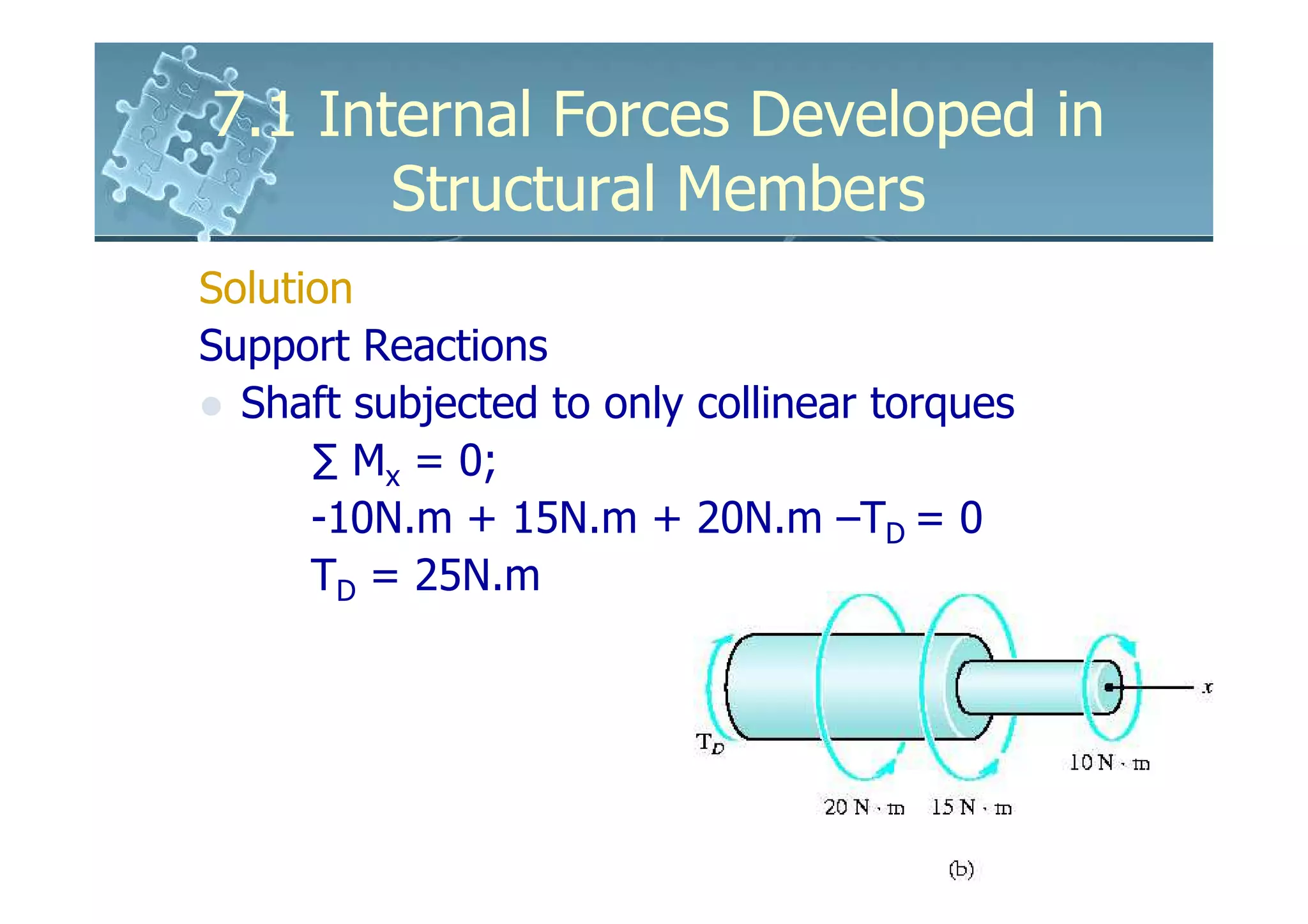
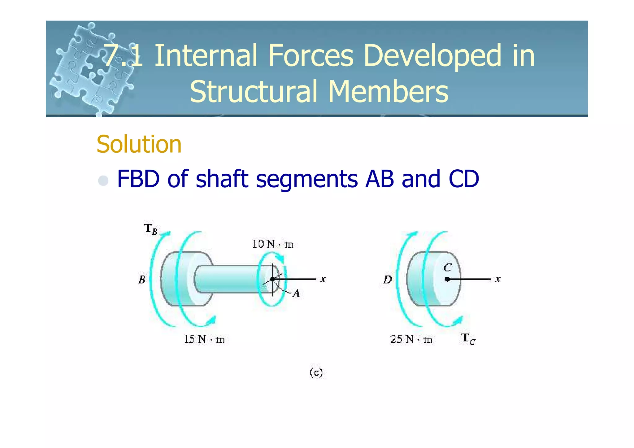
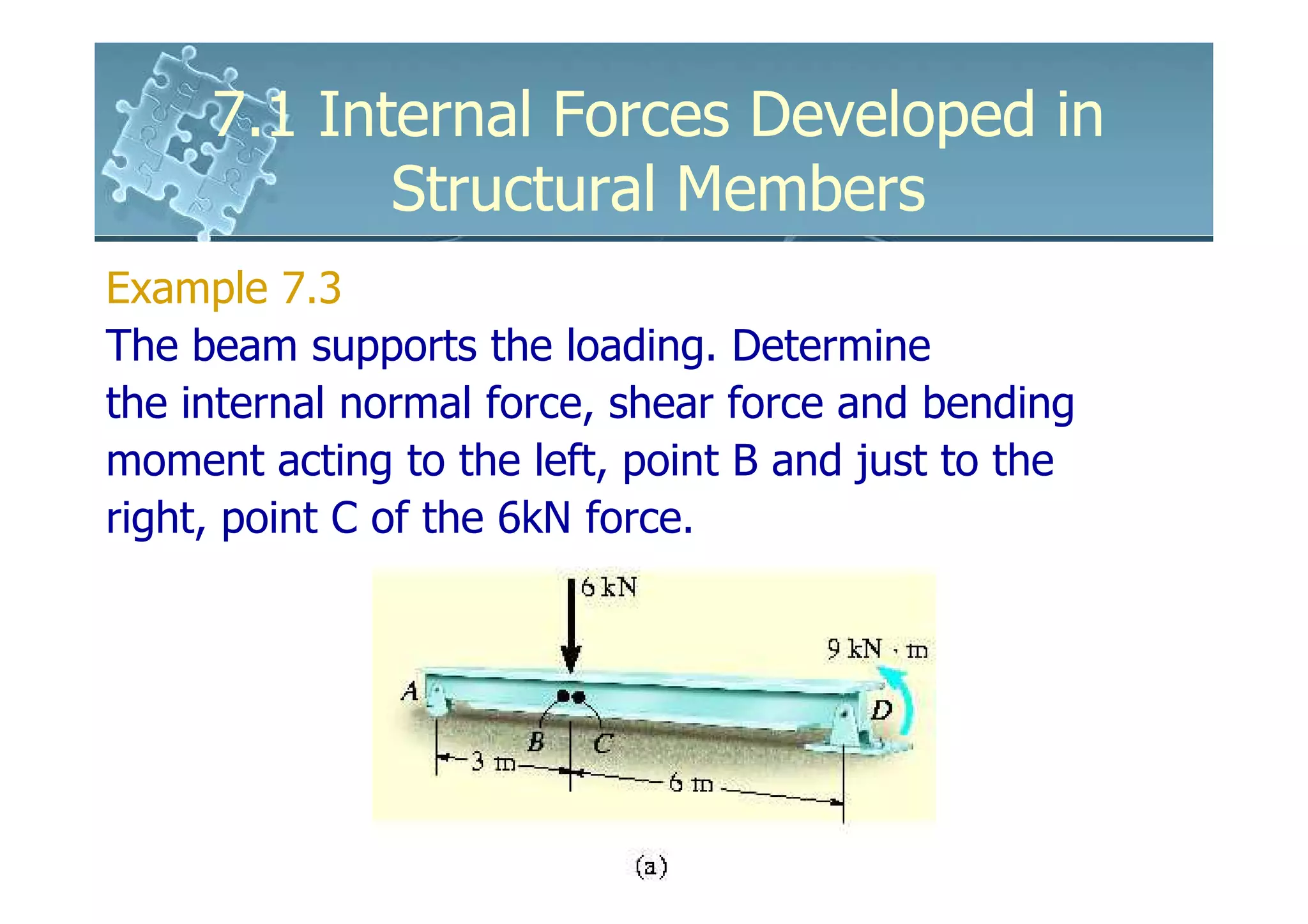
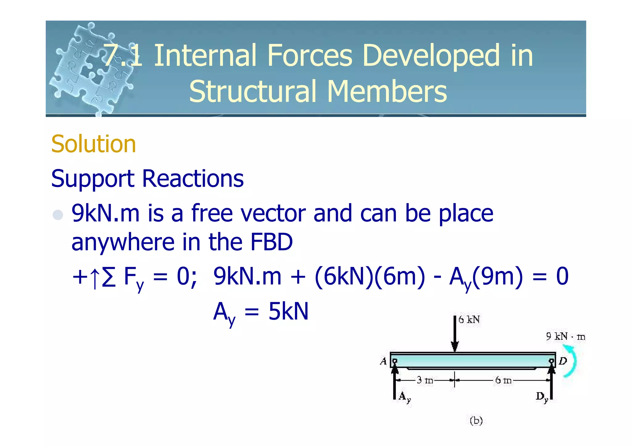
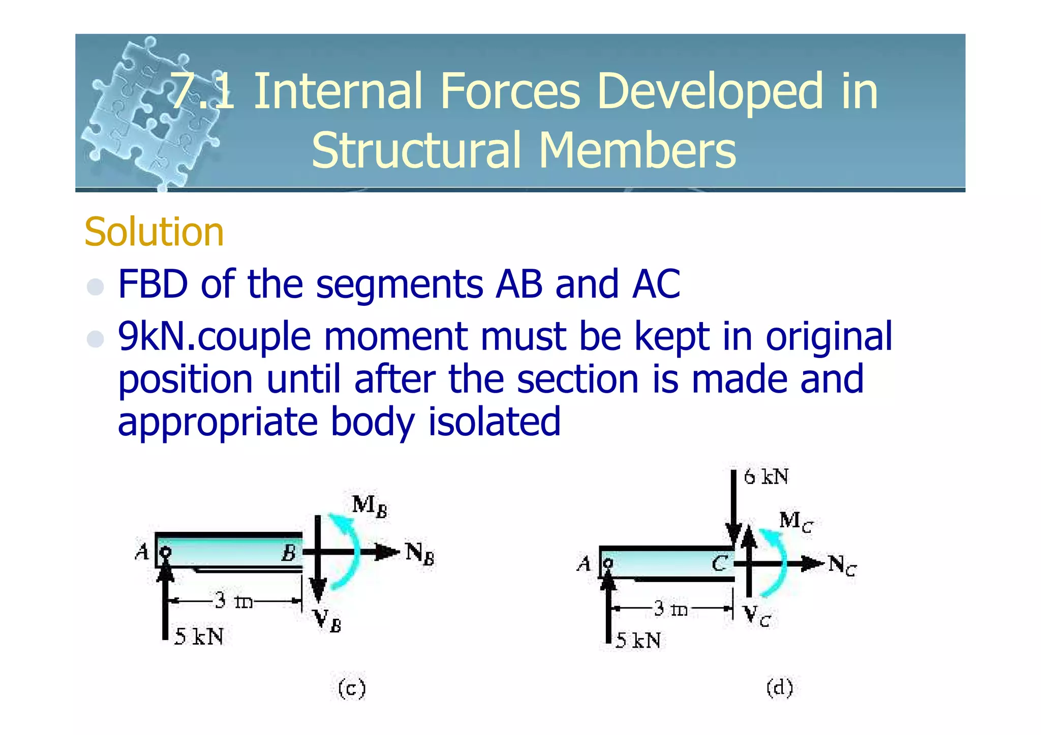
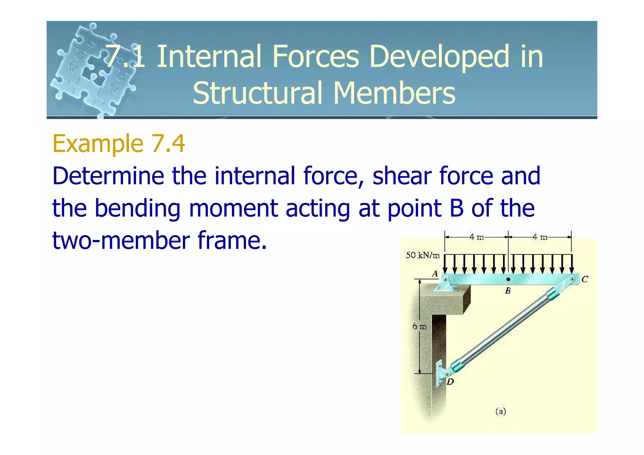
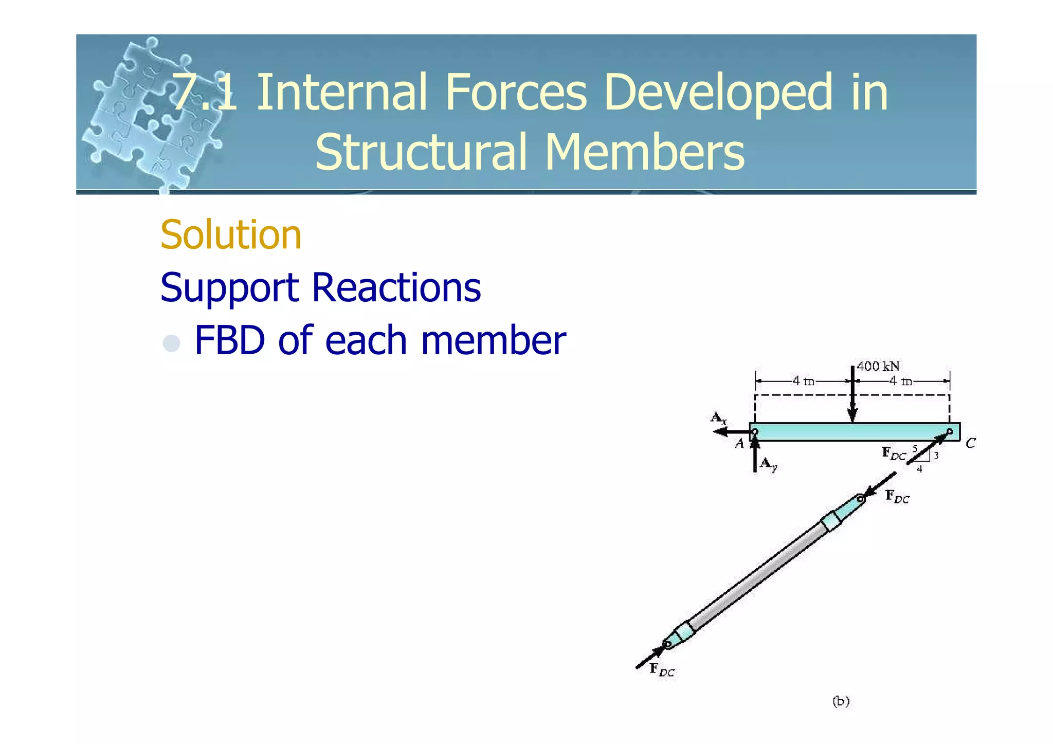
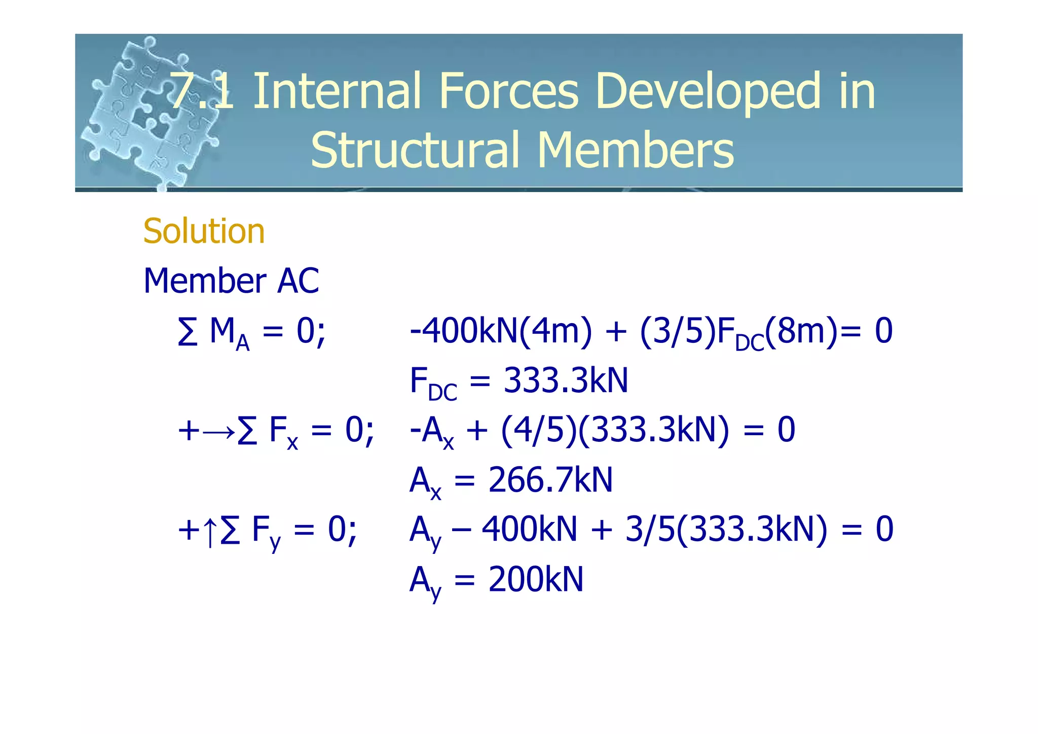
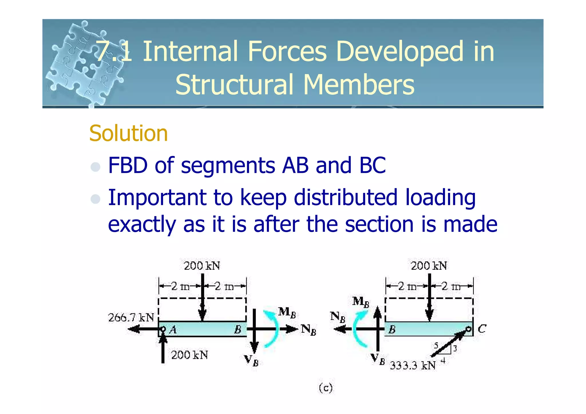
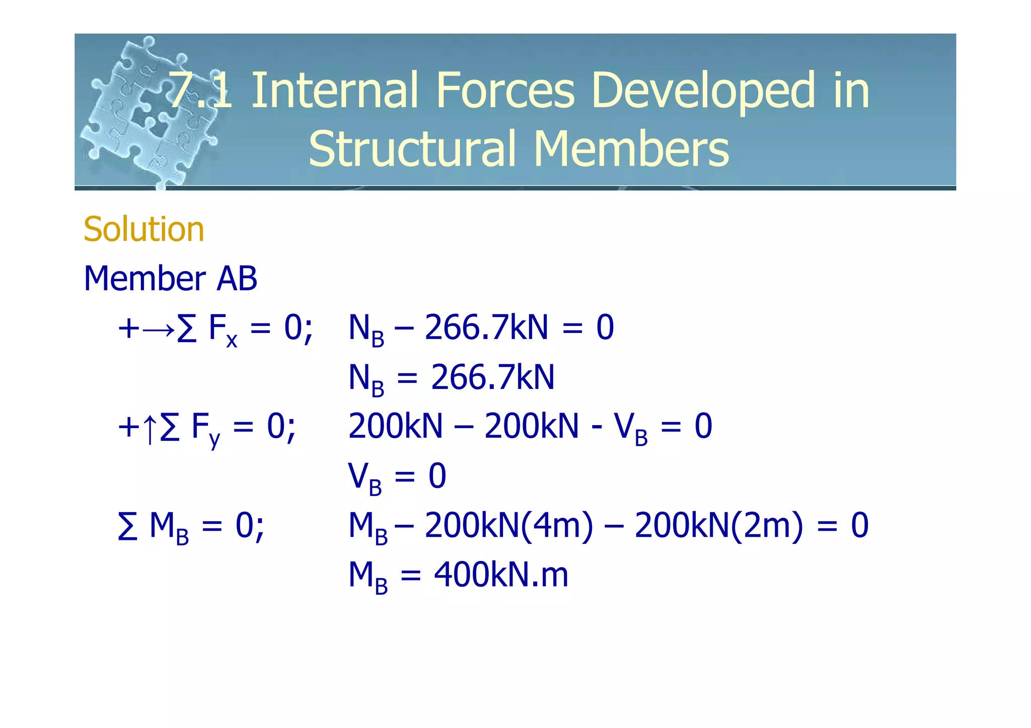
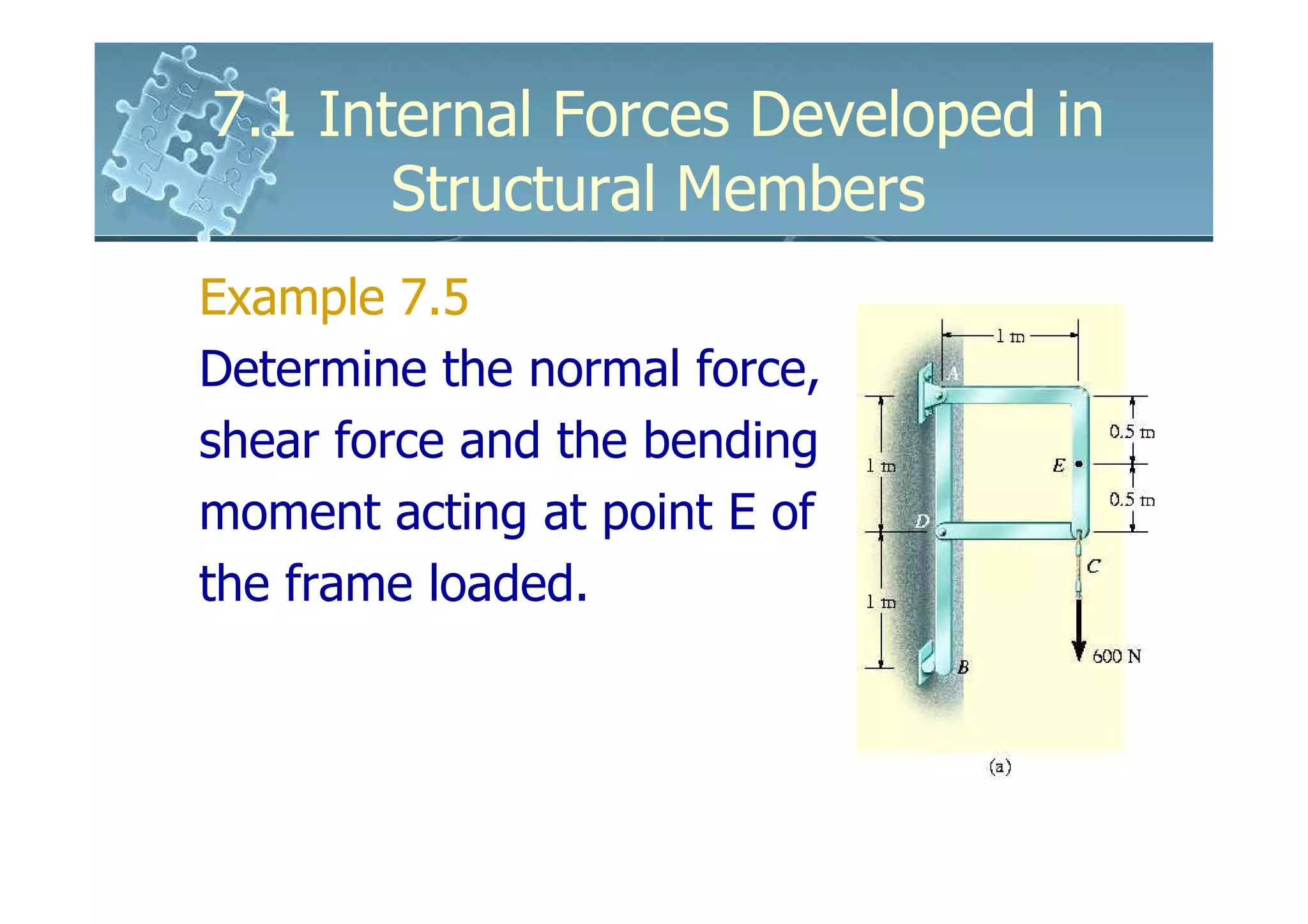
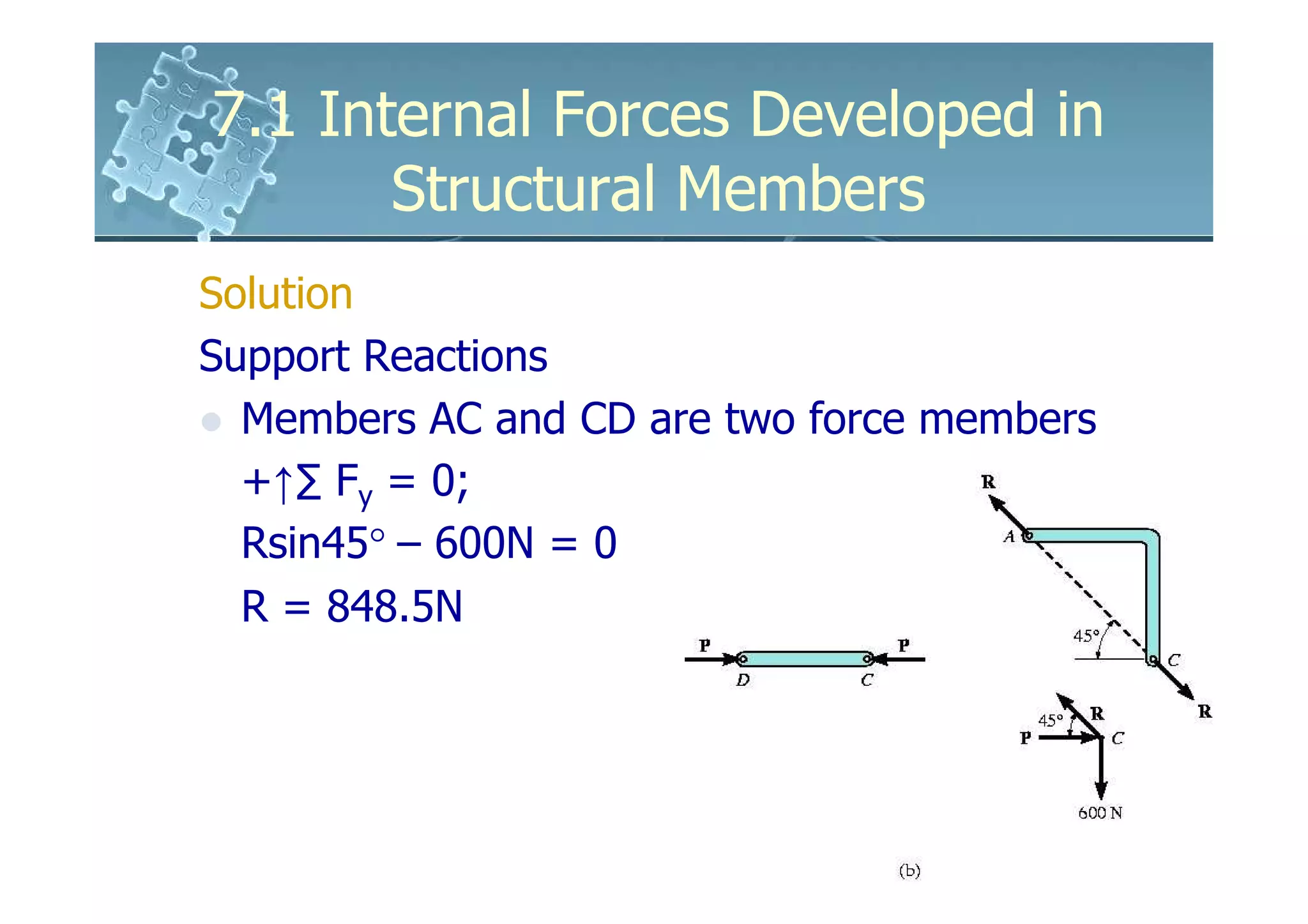
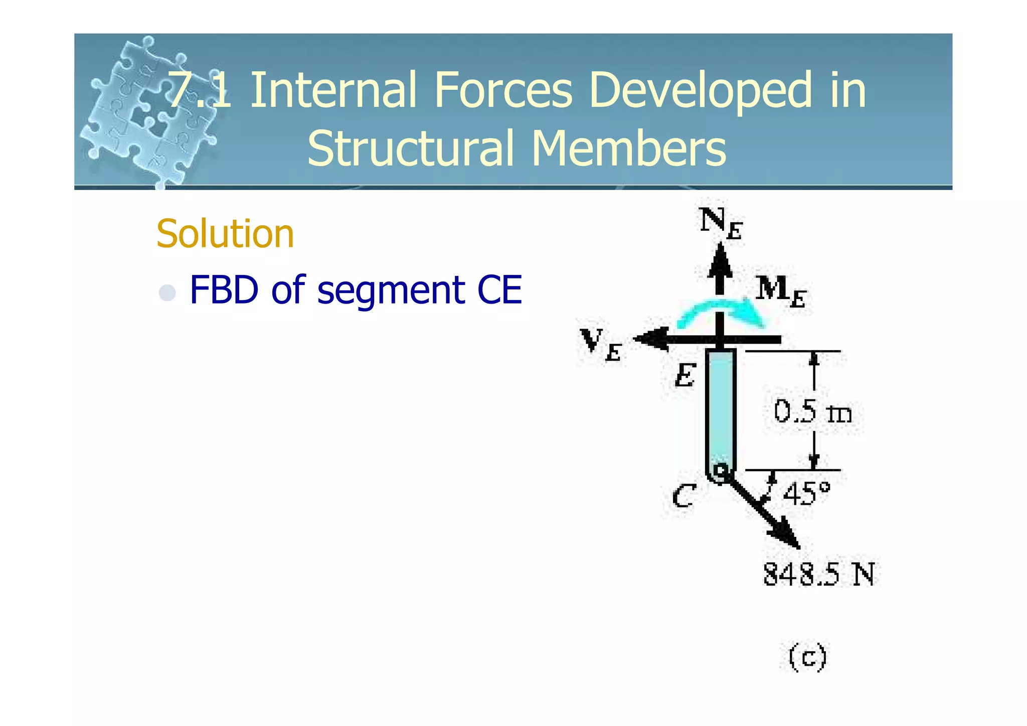
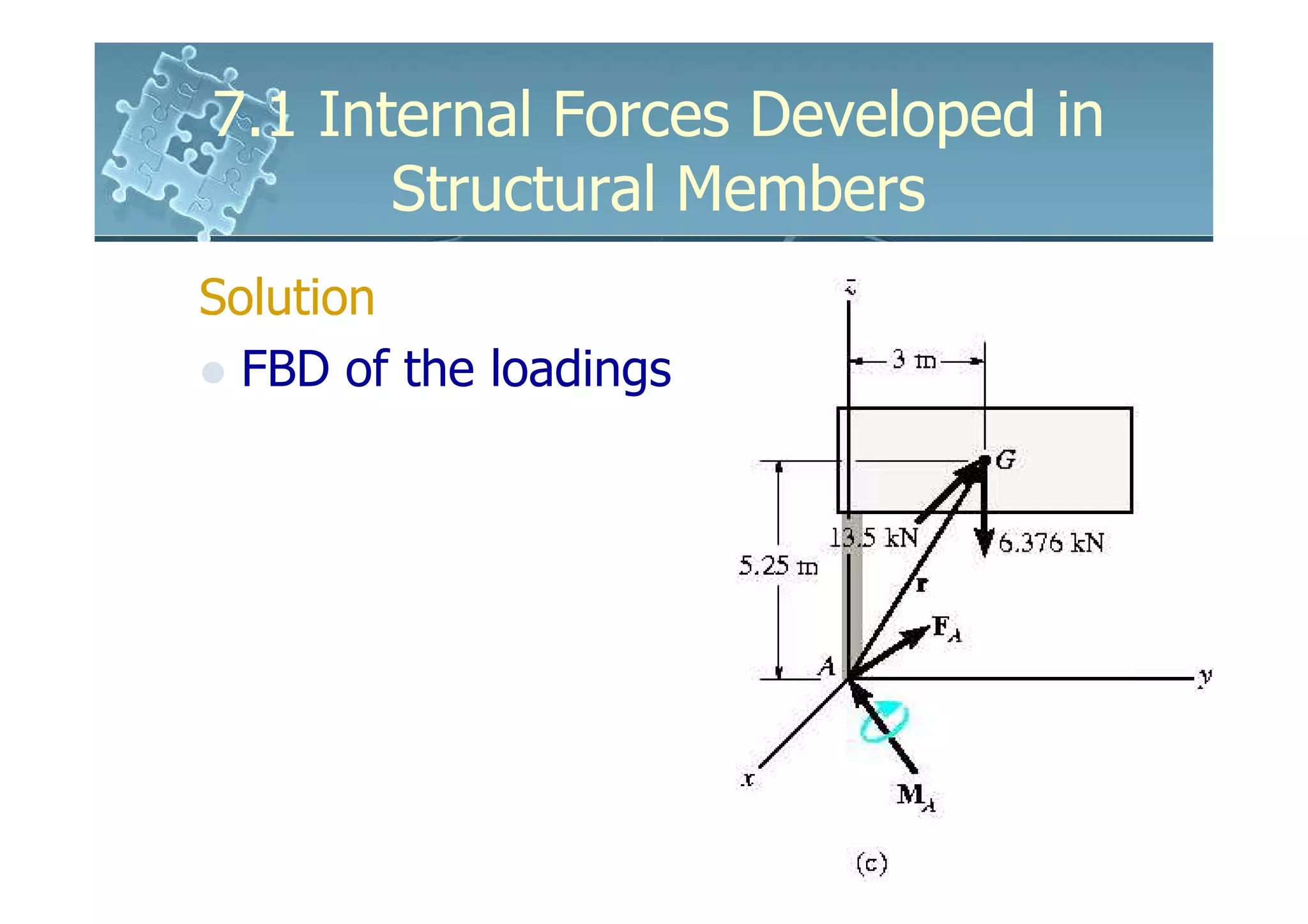
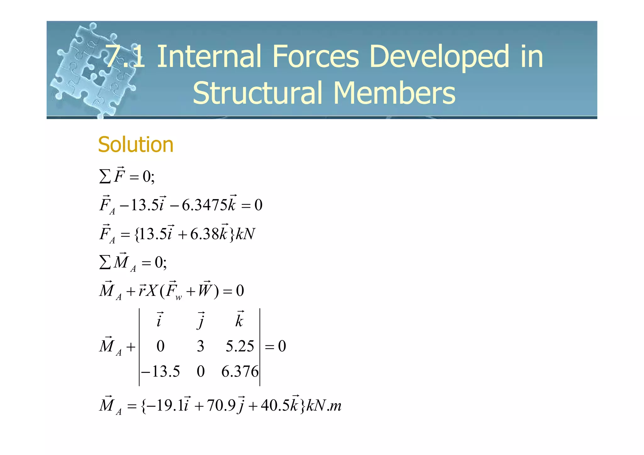
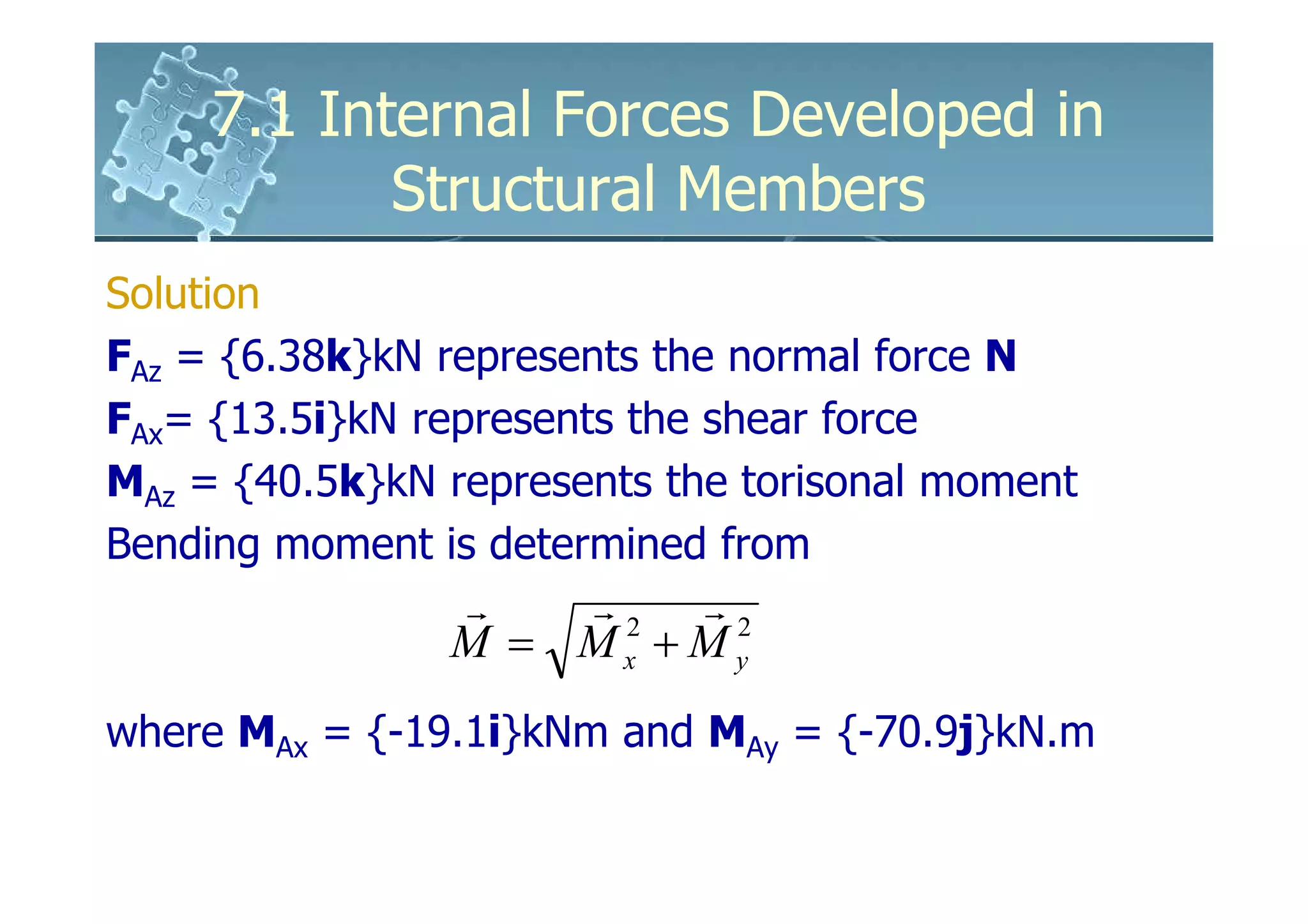
7.1 Internal Forces Developed in
       Structural Members
 The design of any structural or
 mechanical member requires the
 material to be used to be able to resist
 the loading acting on the member
 These internal loadings can be
 determined by the method of sections
7.1 Internal Forces Developed in
          Structural Members
Consider the “simply supported” beam
To determine the internal loadings acting on the cross
section at C, an imaginary section is passed through
the beam, cutting it into two
By doing so, the internal loadings become external on
the FBD
7.1 Internal Forces Developed in
         Structural Members
Since both segments (AC and CB) were in
equilibrium before the sectioning, equilibrium of
the segment is maintained by rectangular force
components and a resultant couple moment
Magnitude of the loadings is determined by the
equilibrium equations
7.1 Internal Forces Developed in
       Structural Members
Force component N, acting normal to the
beam at the cut session and V, acting t
angent to the session are known as normal
or axial force
and the shear force
Couple moment M is
referred as the bending
moment
7.1 Internal Forces Developed in
        Structural Members
For 3D, a general internal force and couple
moment resultant will act at the section
Ny is the normal force, and Vx and Vz are
the shear components
My is the torisonal or
twisting moment, and
Mx and Mz are the
bending moment
components
7.1 Internal Forces Developed in
       Structural Members
 For most applications, these resultant
 loadings will act at the geometric
 center or centroid (C) of the section’s
 cross sectional area
 Although the magnitude of each
 loading differs at different points along
 the axis of the member, the method of
 section can be used to determine the
 values
7.1 Internal Forces Developed in
          Structural Members
Free Body Diagrams
 Since frames and machines are composed of
 multi-force members, each of these members will
 generally be subjected to internal shear, normal
 and bending loadings
 Consider the frame with the blue
 section passed through to
 determine the internal loadings
 at points H, G and F
7.1 Internal Forces Developed in
           Structural Members
Free Body Diagrams
 FBD of the sectioned frame
 At each sectioned member, there is an unknown
 normal force, shear force and bending moment
 3 equilibrium equations cannot be used
 to find 9 unknowns, thus dismember
 the frame and determine
 reactions at each connection
7.1 Internal Forces Developed in
            Structural Members
Free Body Diagrams
  Once done, each member may be sectioned at its
  appropriate point and apply the 3 equilibrium
  equations to determine the unknowns
Example
  FBD of segment DG can be used to determine
  the internal loadings at G
  provided the reactions of
  the pins are known
7.1 Internal Forces Developed in
        Structural Members
Procedure for Analysis
Support Reactions
  Before the member is cut or sectioned,
  determine the member’s support reactions
  Equilibrium equations are used to solve for
  internal loadings during sectioning of the
  members
  If the member is part of a frame or machine, the
  reactions at its connections are determined by
  the methods used in 6.6
7.1 Internal Forces Developed in
       Structural Members
Procedure for Analysis
Free-Body Diagrams
  Keep all distributed loadings, couple
  moments and forces acting on the member
  in their exact locations, then pass an
  imaginary section through the member,
  perpendicular to its axis at the point the
  internal loading is to be determined
  After the session is made, draw the FBD of
  the segment having the least loads
7.1 Internal Forces Developed in
        Structural Members
Procedure for Analysis
Free-Body Diagrams
  Indicate the z, y, z components of the force and
  couple moments and the resultant couple
  moments on the FBD
  If the member is subjected to a coplanar system
  of forces, only N, V and M act at the section
  Determine the sense by inspection; if not,
  assume the sense of the unknown loadings
7.1 Internal Forces Developed in
        Structural Members
Procedure for Analysis
Equations of Equilibrium
  Moments should be summed at the section about
  the axes passing through the centroid or
  geometric center of the member’s cross-sectional
  area in order to eliminate the unknown normal
  and shear forces and thereby, obtain direct
  solutions for the moment components
  If the solution yields a negative result, the sense
  is opposite that assume of the unknown loadings
7.1 Internal Forces Developed in
       Structural Members
          The link on the backhoe is a
          two force member
          It is subjected to both
          bending and axial load at its
          center
          By making the member
          straight, only an axial force
          acts within the member
7.1 Internal Forces Developed in
           Structural Members
Example 7.1
The bar is fixed at its end and is
loaded. Determine the internal normal
force at points B and C.
7.1 Internal Forces Developed in
       Structural Members
Solution
Support Reactions
  FBD of the entire bar
  By inspection, only normal force Ay
  acts at the fixed support
  Ax = 0 and Az = 0
  +↑∑ Fy = 0; 8kN – NB = 0
                  NB = 8kN
7.1 Internal Forces Developed in
       Structural Members
Solution
  FBD of the sectioned bar
  No shear or moment act on
  the sections since they are
  not required for equilibrium
  Choose segment AB and
  DC since they contain the
  least number of forces
7.1 Internal Forces Developed in
       Structural Members
Solution
Segment AB
  +↑∑ Fy = 0;   8kN – NB = 0
                NB = 8kN

Segment DC
  +↑∑ Fy = 0;   NC – 4kN= 0
                NC = 4kN
7.1 Internal Forces Developed in
           Structural Members
Example 7.2
The circular shaft is subjected to three
concentrated torques. Determine the internal
torques at points B and C.
7.1 Internal Forces Developed in
       Structural Members
Solution
Support Reactions
  Shaft subjected to only collinear torques
      ∑ Mx = 0;
      -10N.m + 15N.m + 20N.m –TD = 0
      TD = 25N.m
7.1 Internal Forces Developed in
       Structural Members
Solution
  FBD of shaft segments AB and CD
7.1 Internal Forces Developed in
       Structural Members
Solution
Segment AB
  ∑ Mx = 0;        -10N.m + 15N.m – TB =
  0
              TB = 5N.m

Segment CD
  ∑ Mx = 0;        TC – 25N.m= 0
              TC = 25N.m
7.1 Internal Forces Developed in
            Structural Members
Example 7.3
The beam supports the loading. Determine
the internal normal force, shear force and bending
moment acting to the left, point B and just to the
right, point C of the 6kN force.
7.1 Internal Forces Developed in
           Structural Members
Solution
Support Reactions
  9kN.m is a free vector and can be place
  anywhere in the FBD
  +↑∑ Fy = 0; 9kN.m + (6kN)(6m) - Ay(9m) = 0
               Ay = 5kN
7.1 Internal Forces Developed in
           Structural Members
Solution
  FBD of the segments AB and AC
  9kN.couple moment must be kept in original
  position until after the section is made and
  appropriate body isolated
7.1 Internal Forces Developed in
        Structural Members
Solution
Segment AB
  +→∑ Fx = 0;   NB = 0
  +↑∑ Fy = 0;   5kN – VB = 0
                VB = 5kN
  ∑ MB = 0;     -(5kN)(3m) + MB = 0
                MB = 15kN.m
Segment AC
  +→∑ Fx = 0;   NC = 0
  +↑∑ Fy = 0;   5kN - 6kN + VC = 0
                VC = 1kN
  ∑ MC = 0;     -(5kN)(3m) + MC = 0
                MC = 15kN.m
7.1 Internal Forces Developed in
           Structural Members
Example 7.4
Determine the internal force, shear force and
the bending moment acting at point B of the
two-member frame.
7.1 Internal Forces Developed in
       Structural Members
Solution
Support Reactions
  FBD of each member
7.1 Internal Forces Developed in
        Structural Members
Solution
Member AC
  ∑ MA = 0;  -400kN(4m) + (3/5)FDC(8m)= 0
             FDC = 333.3kN
 +→∑ Fx = 0; -Ax + (4/5)(333.3kN) = 0
             Ax = 266.7kN
 +↑∑ Fy = 0; Ay – 400kN + 3/5(333.3kN) = 0
             Ay = 200kN
7.1 Internal Forces Developed in
       Structural Members
Solution
  FBD of segments AB and BC
  Important to keep distributed loading
  exactly as it is after the section is made
7.1 Internal Forces Developed in
           Structural Members
Solution
Member AB
  +→∑ Fx = 0; NB – 266.7kN = 0
              NB = 266.7kN
  +↑∑ Fy = 0; 200kN – 200kN - VB = 0
              VB = 0
  ∑ MB = 0;   MB – 200kN(4m) – 200kN(2m) = 0
              MB = 400kN.m
7.1 Internal Forces Developed in
       Structural Members
Example 7.5
Determine the normal force,
shear force and the bending
moment acting at point E of
the frame loaded.
7.1 Internal Forces Developed in
       Structural Members
Solution
Support Reactions
  Members AC and CD are two force members
  +↑∑ Fy = 0;
  Rsin45° – 600N = 0
  R = 848.5N
7.1 Internal Forces Developed in
       Structural Members
Solution
  FBD of segment CE
7.1 Internal Forces Developed in
        Structural Members
Solution
  +→∑ Fx = 0; 848.5cos45°N - VE = 0
              VE = 600 N
  +↑∑ Fy = 0; -848.5sin45°N + NE = 0
              NE = 600 N
  ∑ ME = 0;   848.5cos45°N(0.5m) - ME = 0
              ME = 300 N.m

 Results indicate a poor design
 Member AC should be straight to eliminate
 bending within the member
7.1 Internal Forces Developed in
        Structural Members
Example 7.6
The uniform sign has a mass of
650kg and is supported on the fixed
column. Design codes indicate that
the expected maximum uniform
wind loading that will occur in the
area where it is located is 900Pa.
Determine the internal loadings at A
7.1 Internal Forces Developed in
        Structural Members
Solution
  Idealized model for the sign
  Consider FBD of a section above
  A since it dies not involve the
  support reactions
  Sign has weight of
  W = 650(9.81) = 6.376kN
  Wind creates resultant force
  Fw = 900N/m2(6m)(2.5m)
      = 13.5kN
7.1 Internal Forces Developed in
       Structural Members
Solution
  FBD of the loadings
7.1 Internal Forces Developed in
       Structural Members
Solution
   r
∑ F = 0;
r         r            r
FA − 13.5i − 6.3475k = 0
r           r        r
FA = {13.5i + 6.38k }kN
   r
∑ M A = 0;
 r    r r         r
M A + r X ( Fw + W ) = 0
         r       r       r
         i       j      k
 r
MA + 0           3 5.25 = 0
      − 13.5 0 6.376
r           r        r       r
M A = {−19.1i + 70.9 j + 40.5k }kN .m
7.1 Internal Forces Developed in
            Structural Members
Solution
FAz = {6.38k}kN represents the normal force N
FAx= {13.5i}kN represents the shear force
MAz = {40.5k}kN represents the torisonal moment
Bending moment is determined from
                r   r2 r2
                M = Mx + My
where MAx = {-19.1i}kNm and MAy = {-70.9j}kN.m

6161103 7.1 internal forces developed in structural members

  • 1.
    7.1 Internal ForcesDeveloped in Structural Members The design of any structural or mechanical member requires the material to be used to be able to resist the loading acting on the member These internal loadings can be determined by the method of sections
  • 2.
    7.1 Internal ForcesDeveloped in Structural Members Consider the “simply supported” beam To determine the internal loadings acting on the cross section at C, an imaginary section is passed through the beam, cutting it into two By doing so, the internal loadings become external on the FBD
  • 3.
    7.1 Internal ForcesDeveloped in Structural Members Since both segments (AC and CB) were in equilibrium before the sectioning, equilibrium of the segment is maintained by rectangular force components and a resultant couple moment Magnitude of the loadings is determined by the equilibrium equations
  • 4.
    7.1 Internal ForcesDeveloped in Structural Members Force component N, acting normal to the beam at the cut session and V, acting t angent to the session are known as normal or axial force and the shear force Couple moment M is referred as the bending moment
  • 5.
    7.1 Internal ForcesDeveloped in Structural Members For 3D, a general internal force and couple moment resultant will act at the section Ny is the normal force, and Vx and Vz are the shear components My is the torisonal or twisting moment, and Mx and Mz are the bending moment components
  • 6.
    7.1 Internal ForcesDeveloped in Structural Members For most applications, these resultant loadings will act at the geometric center or centroid (C) of the section’s cross sectional area Although the magnitude of each loading differs at different points along the axis of the member, the method of section can be used to determine the values
  • 7.
    7.1 Internal ForcesDeveloped in Structural Members Free Body Diagrams Since frames and machines are composed of multi-force members, each of these members will generally be subjected to internal shear, normal and bending loadings Consider the frame with the blue section passed through to determine the internal loadings at points H, G and F
  • 8.
    7.1 Internal ForcesDeveloped in Structural Members Free Body Diagrams FBD of the sectioned frame At each sectioned member, there is an unknown normal force, shear force and bending moment 3 equilibrium equations cannot be used to find 9 unknowns, thus dismember the frame and determine reactions at each connection
  • 9.
    7.1 Internal ForcesDeveloped in Structural Members Free Body Diagrams Once done, each member may be sectioned at its appropriate point and apply the 3 equilibrium equations to determine the unknowns Example FBD of segment DG can be used to determine the internal loadings at G provided the reactions of the pins are known
  • 10.
    7.1 Internal ForcesDeveloped in Structural Members Procedure for Analysis Support Reactions Before the member is cut or sectioned, determine the member’s support reactions Equilibrium equations are used to solve for internal loadings during sectioning of the members If the member is part of a frame or machine, the reactions at its connections are determined by the methods used in 6.6
  • 11.
    7.1 Internal ForcesDeveloped in Structural Members Procedure for Analysis Free-Body Diagrams Keep all distributed loadings, couple moments and forces acting on the member in their exact locations, then pass an imaginary section through the member, perpendicular to its axis at the point the internal loading is to be determined After the session is made, draw the FBD of the segment having the least loads
  • 12.
    7.1 Internal ForcesDeveloped in Structural Members Procedure for Analysis Free-Body Diagrams Indicate the z, y, z components of the force and couple moments and the resultant couple moments on the FBD If the member is subjected to a coplanar system of forces, only N, V and M act at the section Determine the sense by inspection; if not, assume the sense of the unknown loadings
  • 13.
    7.1 Internal ForcesDeveloped in Structural Members Procedure for Analysis Equations of Equilibrium Moments should be summed at the section about the axes passing through the centroid or geometric center of the member’s cross-sectional area in order to eliminate the unknown normal and shear forces and thereby, obtain direct solutions for the moment components If the solution yields a negative result, the sense is opposite that assume of the unknown loadings
  • 14.
    7.1 Internal ForcesDeveloped in Structural Members The link on the backhoe is a two force member It is subjected to both bending and axial load at its center By making the member straight, only an axial force acts within the member
  • 15.
    7.1 Internal ForcesDeveloped in Structural Members Example 7.1 The bar is fixed at its end and is loaded. Determine the internal normal force at points B and C.
  • 16.
    7.1 Internal ForcesDeveloped in Structural Members Solution Support Reactions FBD of the entire bar By inspection, only normal force Ay acts at the fixed support Ax = 0 and Az = 0 +↑∑ Fy = 0; 8kN – NB = 0 NB = 8kN
  • 17.
    7.1 Internal ForcesDeveloped in Structural Members Solution FBD of the sectioned bar No shear or moment act on the sections since they are not required for equilibrium Choose segment AB and DC since they contain the least number of forces
  • 18.
    7.1 Internal ForcesDeveloped in Structural Members Solution Segment AB +↑∑ Fy = 0; 8kN – NB = 0 NB = 8kN Segment DC +↑∑ Fy = 0; NC – 4kN= 0 NC = 4kN
  • 19.
    7.1 Internal ForcesDeveloped in Structural Members Example 7.2 The circular shaft is subjected to three concentrated torques. Determine the internal torques at points B and C.
  • 20.
    7.1 Internal ForcesDeveloped in Structural Members Solution Support Reactions Shaft subjected to only collinear torques ∑ Mx = 0; -10N.m + 15N.m + 20N.m –TD = 0 TD = 25N.m
  • 21.
    7.1 Internal ForcesDeveloped in Structural Members Solution FBD of shaft segments AB and CD
  • 22.
    7.1 Internal ForcesDeveloped in Structural Members Solution Segment AB ∑ Mx = 0; -10N.m + 15N.m – TB = 0 TB = 5N.m Segment CD ∑ Mx = 0; TC – 25N.m= 0 TC = 25N.m
  • 23.
    7.1 Internal ForcesDeveloped in Structural Members Example 7.3 The beam supports the loading. Determine the internal normal force, shear force and bending moment acting to the left, point B and just to the right, point C of the 6kN force.
  • 24.
    7.1 Internal ForcesDeveloped in Structural Members Solution Support Reactions 9kN.m is a free vector and can be place anywhere in the FBD +↑∑ Fy = 0; 9kN.m + (6kN)(6m) - Ay(9m) = 0 Ay = 5kN
  • 25.
    7.1 Internal ForcesDeveloped in Structural Members Solution FBD of the segments AB and AC 9kN.couple moment must be kept in original position until after the section is made and appropriate body isolated
  • 26.
    7.1 Internal ForcesDeveloped in Structural Members Solution Segment AB +→∑ Fx = 0; NB = 0 +↑∑ Fy = 0; 5kN – VB = 0 VB = 5kN ∑ MB = 0; -(5kN)(3m) + MB = 0 MB = 15kN.m Segment AC +→∑ Fx = 0; NC = 0 +↑∑ Fy = 0; 5kN - 6kN + VC = 0 VC = 1kN ∑ MC = 0; -(5kN)(3m) + MC = 0 MC = 15kN.m
  • 27.
    7.1 Internal ForcesDeveloped in Structural Members Example 7.4 Determine the internal force, shear force and the bending moment acting at point B of the two-member frame.
  • 28.
    7.1 Internal ForcesDeveloped in Structural Members Solution Support Reactions FBD of each member
  • 29.
    7.1 Internal ForcesDeveloped in Structural Members Solution Member AC ∑ MA = 0; -400kN(4m) + (3/5)FDC(8m)= 0 FDC = 333.3kN +→∑ Fx = 0; -Ax + (4/5)(333.3kN) = 0 Ax = 266.7kN +↑∑ Fy = 0; Ay – 400kN + 3/5(333.3kN) = 0 Ay = 200kN
  • 30.
    7.1 Internal ForcesDeveloped in Structural Members Solution FBD of segments AB and BC Important to keep distributed loading exactly as it is after the section is made
  • 31.
    7.1 Internal ForcesDeveloped in Structural Members Solution Member AB +→∑ Fx = 0; NB – 266.7kN = 0 NB = 266.7kN +↑∑ Fy = 0; 200kN – 200kN - VB = 0 VB = 0 ∑ MB = 0; MB – 200kN(4m) – 200kN(2m) = 0 MB = 400kN.m
  • 32.
    7.1 Internal ForcesDeveloped in Structural Members Example 7.5 Determine the normal force, shear force and the bending moment acting at point E of the frame loaded.
  • 33.
    7.1 Internal ForcesDeveloped in Structural Members Solution Support Reactions Members AC and CD are two force members +↑∑ Fy = 0; Rsin45° – 600N = 0 R = 848.5N
  • 34.
    7.1 Internal ForcesDeveloped in Structural Members Solution FBD of segment CE
  • 35.
    7.1 Internal ForcesDeveloped in Structural Members Solution +→∑ Fx = 0; 848.5cos45°N - VE = 0 VE = 600 N +↑∑ Fy = 0; -848.5sin45°N + NE = 0 NE = 600 N ∑ ME = 0; 848.5cos45°N(0.5m) - ME = 0 ME = 300 N.m Results indicate a poor design Member AC should be straight to eliminate bending within the member
  • 36.
    7.1 Internal ForcesDeveloped in Structural Members Example 7.6 The uniform sign has a mass of 650kg and is supported on the fixed column. Design codes indicate that the expected maximum uniform wind loading that will occur in the area where it is located is 900Pa. Determine the internal loadings at A
  • 37.
    7.1 Internal ForcesDeveloped in Structural Members Solution Idealized model for the sign Consider FBD of a section above A since it dies not involve the support reactions Sign has weight of W = 650(9.81) = 6.376kN Wind creates resultant force Fw = 900N/m2(6m)(2.5m) = 13.5kN
  • 38.
    7.1 Internal ForcesDeveloped in Structural Members Solution FBD of the loadings
  • 39.
    7.1 Internal ForcesDeveloped in Structural Members Solution r ∑ F = 0; r r r FA − 13.5i − 6.3475k = 0 r r r FA = {13.5i + 6.38k }kN r ∑ M A = 0; r r r r M A + r X ( Fw + W ) = 0 r r r i j k r MA + 0 3 5.25 = 0 − 13.5 0 6.376 r r r r M A = {−19.1i + 70.9 j + 40.5k }kN .m
  • 40.
    7.1 Internal ForcesDeveloped in Structural Members Solution FAz = {6.38k}kN represents the normal force N FAx= {13.5i}kN represents the shear force MAz = {40.5k}kN represents the torisonal moment Bending moment is determined from r r2 r2 M = Mx + My where MAx = {-19.1i}kNm and MAy = {-70.9j}kN.m