Downloaded 417 times


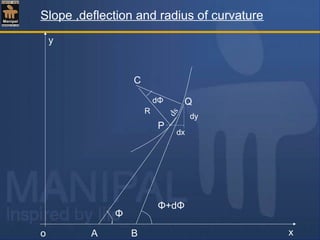
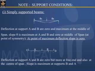
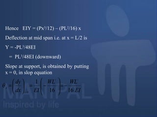
![From equation(1),
R= secφ /(dφ/dx) = sec
3
φ /(d
2
y/dx2
)
1/R=(d
2
y/dx
2
)/sec
3
φ =(d2
y/dx2
)/ (sec2
φ)3/2
= (d2
y/dx2
)/ (1+tan2
φ)3/2
=(d
2
y/dx
2
)/[1+(dy/dx)
2
]
3/2
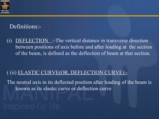
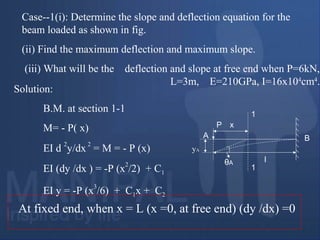
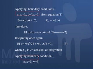
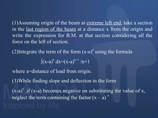
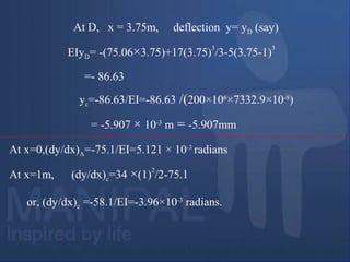
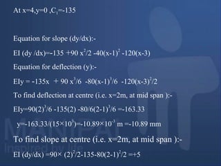
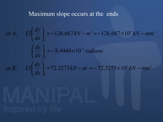
In any practical case of bending of beams, the slope (dy/dx) is
very small (because curve is almost flat); hence (dy/dx)2
can
be ignored
so, 1/R=d
2
y/dx
2
From relation ,M/I=E/R
1/R=M/EI=d2
y/dx2
M=EI(d2
y/dx2
)](https://image.slidesharecdn.com/deflection-180511185328/85/Deflection-11-320.jpg)

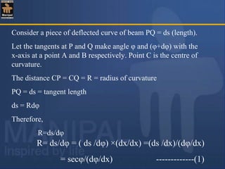
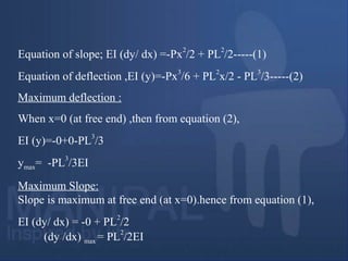
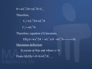
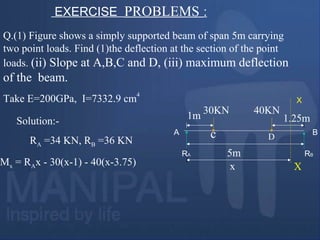
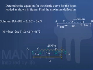
![Therefore,
- (PL
2
/2) + C1= 0
C1= PL
2
/2
At x = L, y = 0,
-PL
3
/6+(PL
2
/2) L+C2=0
or,C2= PL
3
/6 - PL
3
/2
= PL
3
/6[1-3]= - PL
3
/3
Therefore ,C2= - PL
3
/3](https://image.slidesharecdn.com/deflection-180511185328/85/Deflection-19-320.jpg)
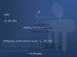
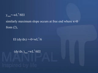
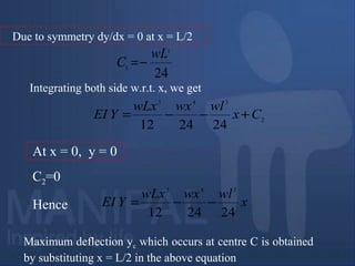


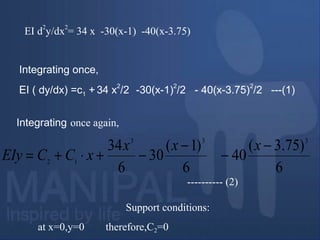
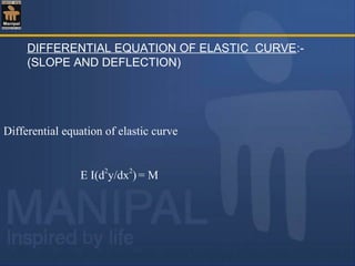
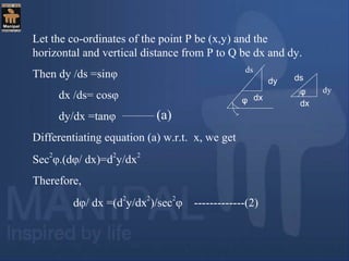
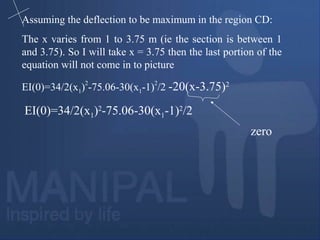
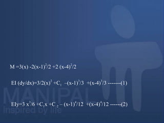
![(dy/dx)D =[17 ×(3.75)2-75.06-15 ×(2.75)2] × 1/EI
(when x=3.75m)
=50.525/EI=3.445 radians.
(dy/ dx) at B=1/EI[17 ×(5)2-75.06-15 ×(4)2-20 ×(1.25)2]
=78.65/EI=5.363 × 10-3
rad =0.197 degree
Assuming the deflection to be maximum in the region CD:
(at point of maximum deflection dy/dx = 0)](https://image.slidesharecdn.com/deflection-180511185328/85/Deflection-38-320.jpg)
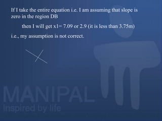
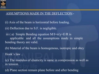
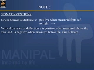
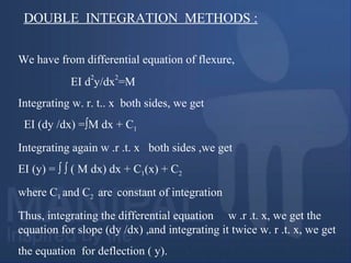
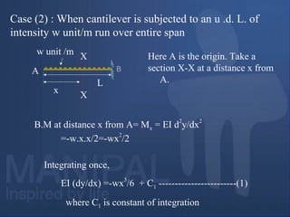
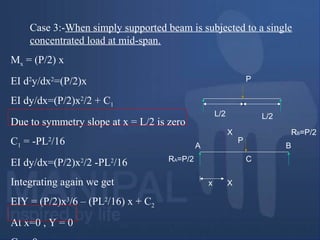
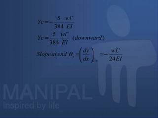
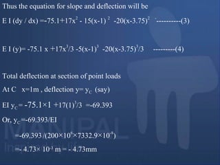
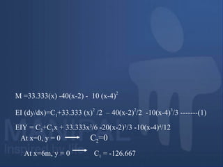
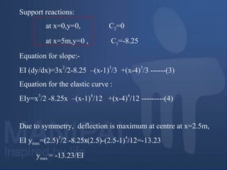
![(Q-2)
(A) Obtain the equation for slope and elastic curve for the beam
loaded as shown in figure and find the deflection and slope at mid-
point of beam.
Take EI=15× 103
kNm
2
(B) Find the slope at A,C and D
Solution:-
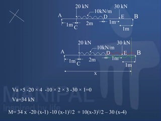
Reactions
RA=1/4[80×3+120]
=90KN( )
RB =80-90=-10kN=10( )
80KN
1m
120kNm
x
X
X
2m1m
A
c
D
B](https://image.slidesharecdn.com/deflection-180511185328/85/Deflection-42-320.jpg)
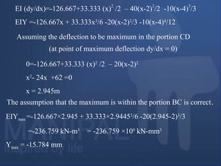
![Alternatively, RB =1/4[80×1-120]
=-10KN =10 KN( )
EI (dy /dx )= C1 + 90x
2
/2 - 80(x-1)
2
/2 –120 (x-3) -------(1)
EI(y)= C2+C1(x) + 90 x
3
/6 -80(x-1)
3
/6 -120(x-3)
2
/2 ------(2)
Support reactions
at x = 0 ,y = 0 ,
C = 0
MX= 90x - 80(x-1) -120(x-3)
0
Mx = 90 x – 80 (x-1) – 120 (x-3)0](https://image.slidesharecdn.com/deflection-180511185328/85/Deflection-43-320.jpg)
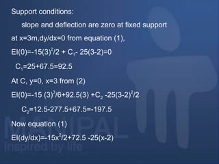
![dy/dx =5/(15×10
3
)=3.33×10
-4
radians~ 0.019°
=19.1×10
-3
degree ~ 0.02°
(b)θA(at x=0) =-135/EI=-135/(15×103
)
θC ( at x=1m ) =[45× (1)
2
-135 ×1)/15 × 10
3
=-90/15 × 10
3
radian
D (at x=3m )= [45 ×(3)
2
-135-40(2)
2
] =110/15 × 10
3
radian](https://image.slidesharecdn.com/deflection-180511185328/85/Deflection-45-320.jpg)

![[Ans (i)θA=WL
3
/48EI (ii)A =7wL
4
/384EI( ) (iii)P=7wL/128]
L/2 L/2
w/m
A B
46](https://image.slidesharecdn.com/deflection-180511185328/85/Deflection-59-320.jpg)
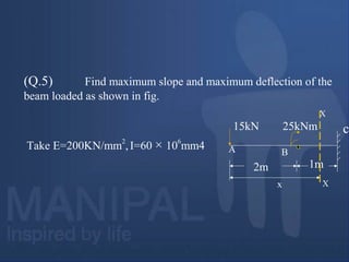
![Q- (2 ) Determine the values of deflections at points C,D and E in
the beam as shown in figure.Take E=2*10
5
MPa ; I= 60 *10
8
mm
4
1m 2m
10kN/m
1m 1m
20kN
30kN
A C D E B
[C=0.0603mm(downward), D=0.0953mm(downward)
E=0.0606mm(downward)]
47](https://image.slidesharecdn.com/deflection-180511185328/85/Deflection-60-320.jpg)
![.
Q-(3) Find the position and magnitude of maximum deflection for
the beam loaded as shown in fig.
Take E=200GPa ,I=7500cm4
.
3KN/m20 KN
A
D B
X
4m 4m 4m
C
X
X
[Ans:ymax at 3.7 m from A=-118/EI=7.99mm
yc=-32/EI=-2.13mm]
48](https://image.slidesharecdn.com/deflection-180511185328/85/Deflection-61-320.jpg)
![Q-(4) Determine the magnitude and position of maximum
deflection for the beam loaded as shown in fig.
Take EI=800Nm
2
E
B
D
A
C
1m1m 1m 1m
[Ans:ymax =80 mm at 1.59m from A , yE =73mm]
120kNm
80kN 20kN
49](https://image.slidesharecdn.com/deflection-180511185328/85/Deflection-62-320.jpg)
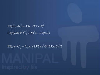
![Q-(5) Find the deflection and slope at free end for loaded
beam shown in fig.
4kN/m
10 KN
1m 2m 1m
DA
B
C
[Ans:θD=62.33/EI, y=-191/EI ]
Q-(6 ) Find the deflection at C and magnitude of
maximum deflection. Take EI=40MN-m
2
4m 2m
200KN1m
BA
C
[Ans:ymax=-13.45mm, yC=-13.33mm ]
50](https://image.slidesharecdn.com/deflection-180511185328/85/Deflection-63-320.jpg)


This document discusses beam design criteria and deflection behavior of beams. It covers two key criteria for beam design: 1) Strength criterion - the beam cross section must be strong enough to resist bending moments and shear forces. 2) Stiffness criterion - the maximum deflection of the beam cannot exceed a limit and the beam must be stiff enough to resist deflections from loading. It then defines deflection, slope, elastic curve, and flexural rigidity. It presents the differential equation that relates bending moment, slope, and deflection. Methods for calculating slope and deflection including double integration, Macaulay's method, and others are also summarized.


