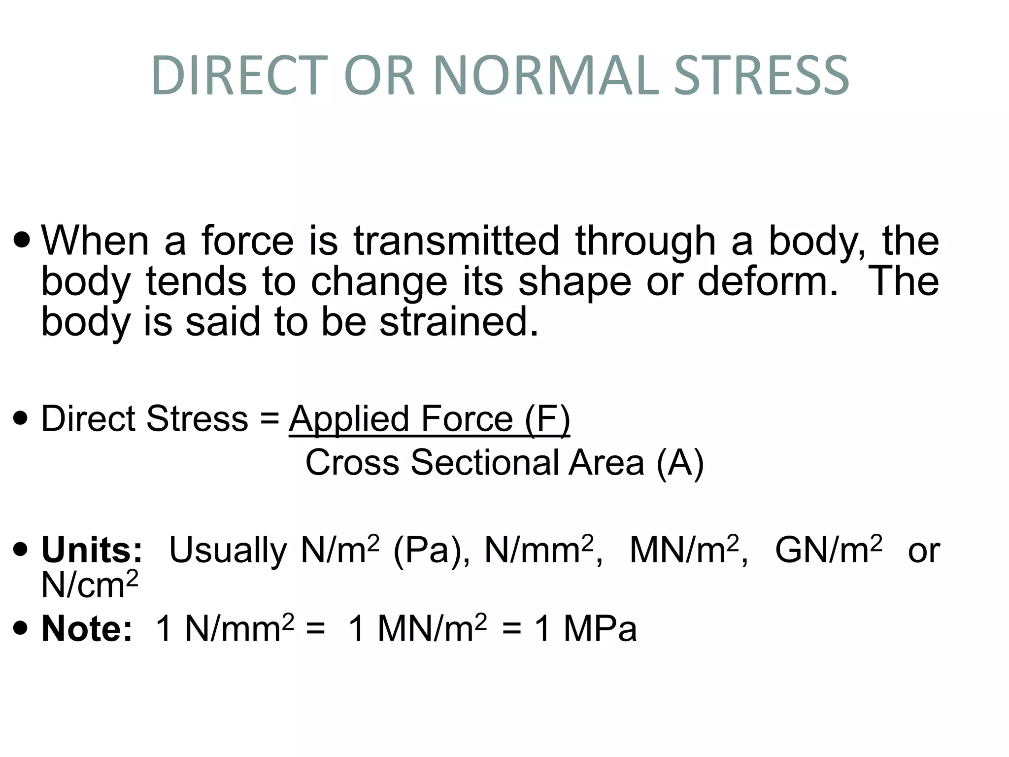
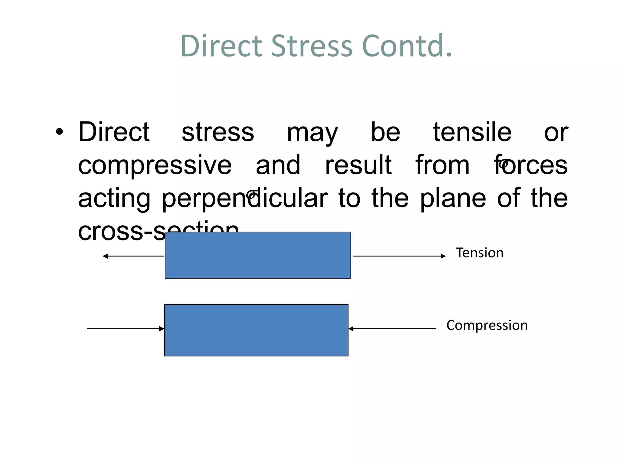
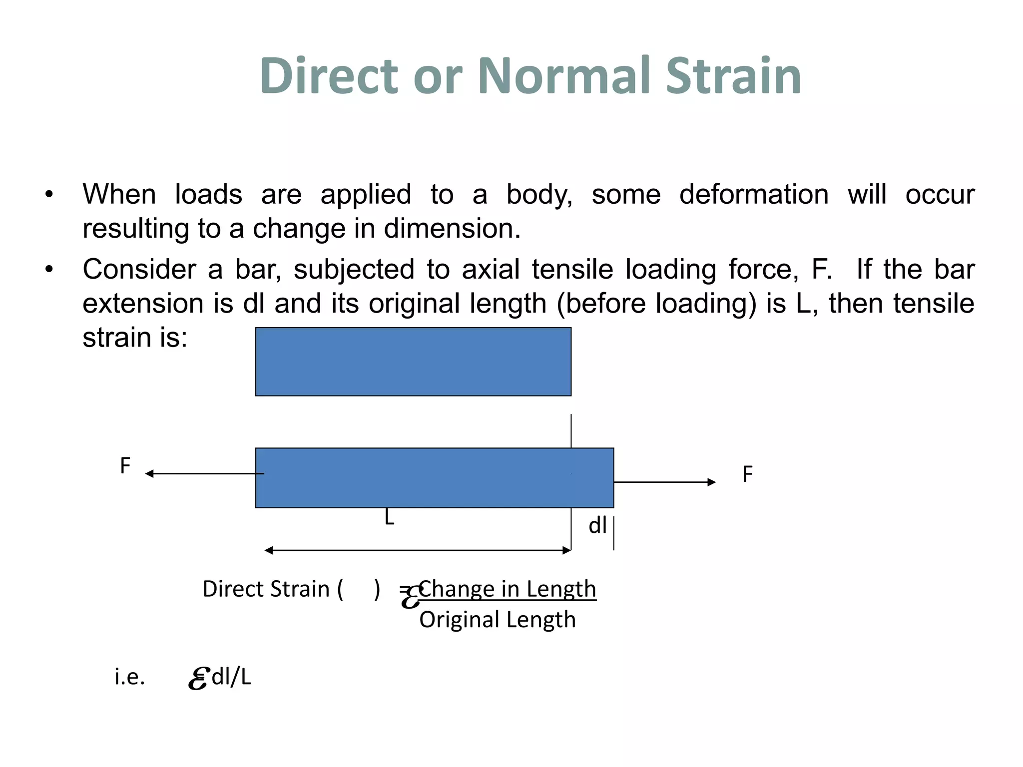
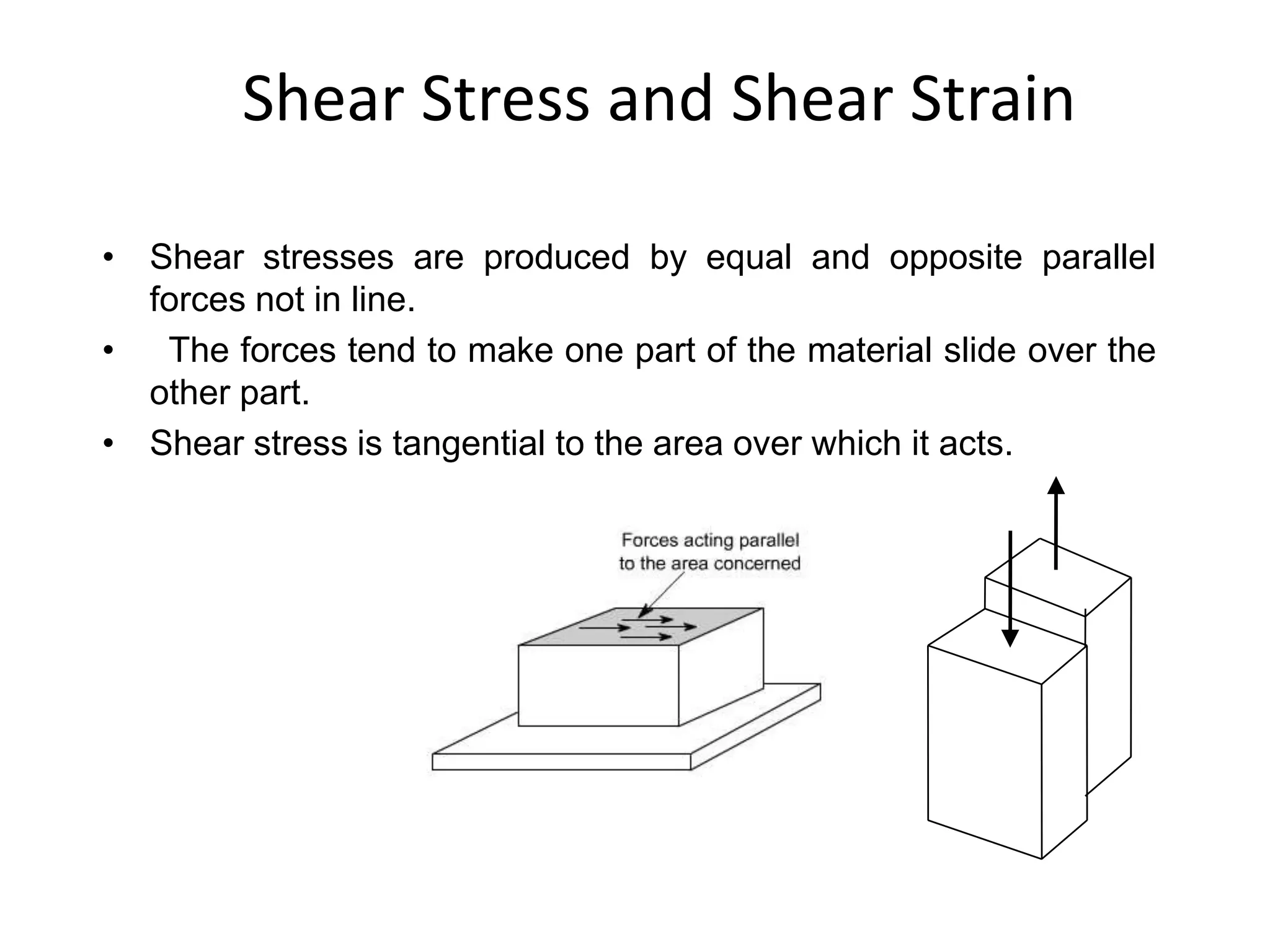
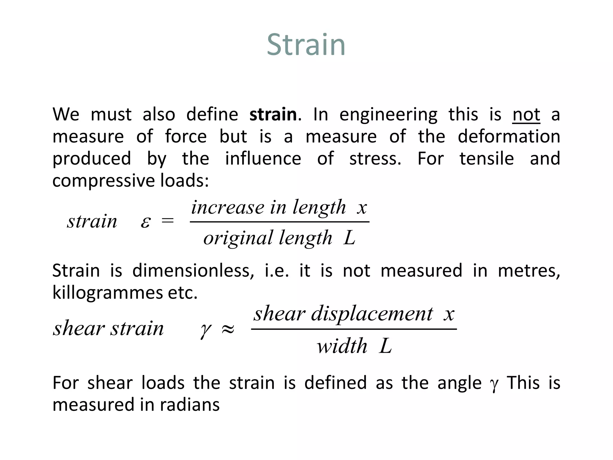
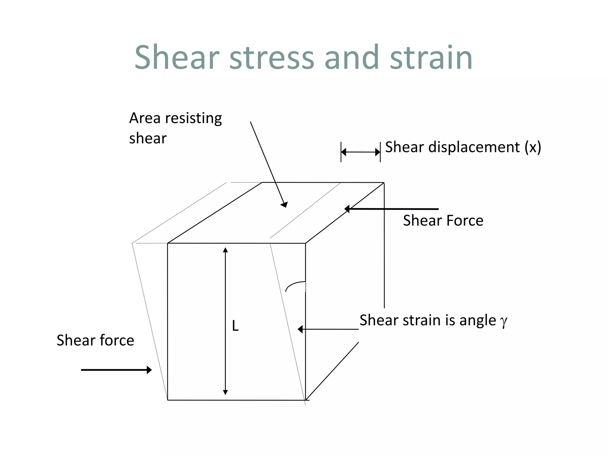
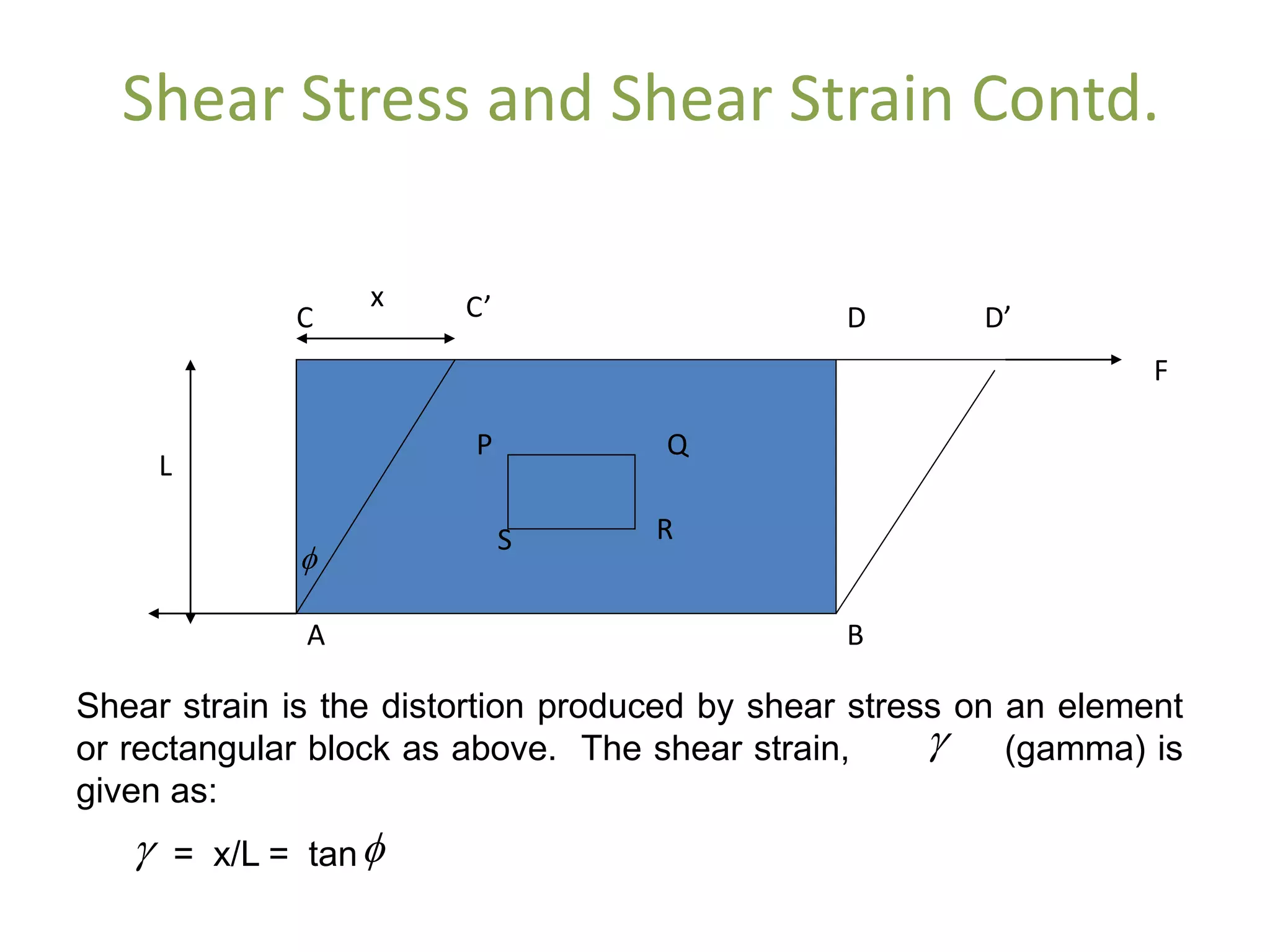
1. When a force is applied to a body, it causes the body to deform or change shape. This deformation is called strain. Direct stress is calculated as the applied force divided by the cross-sectional area.
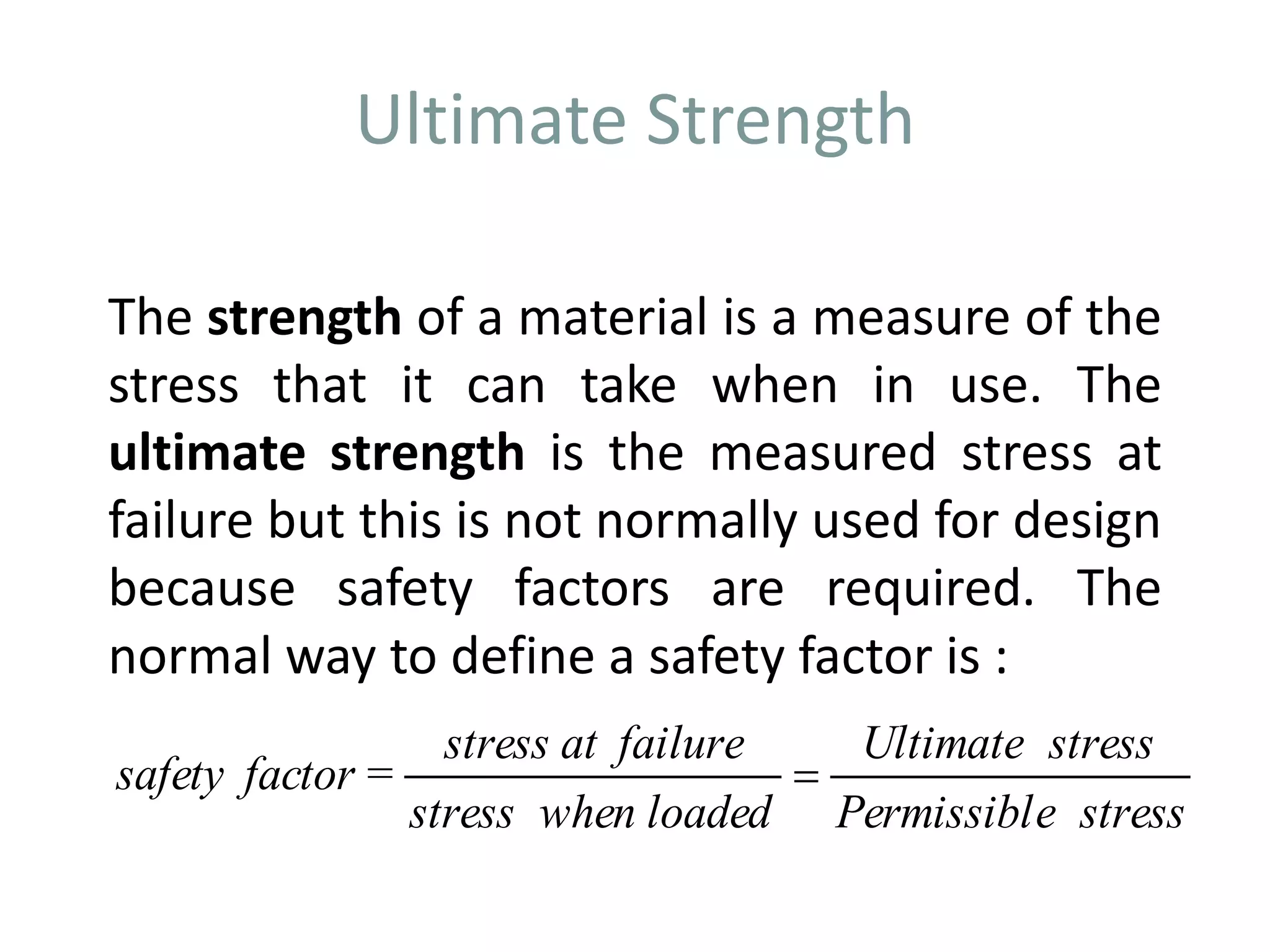
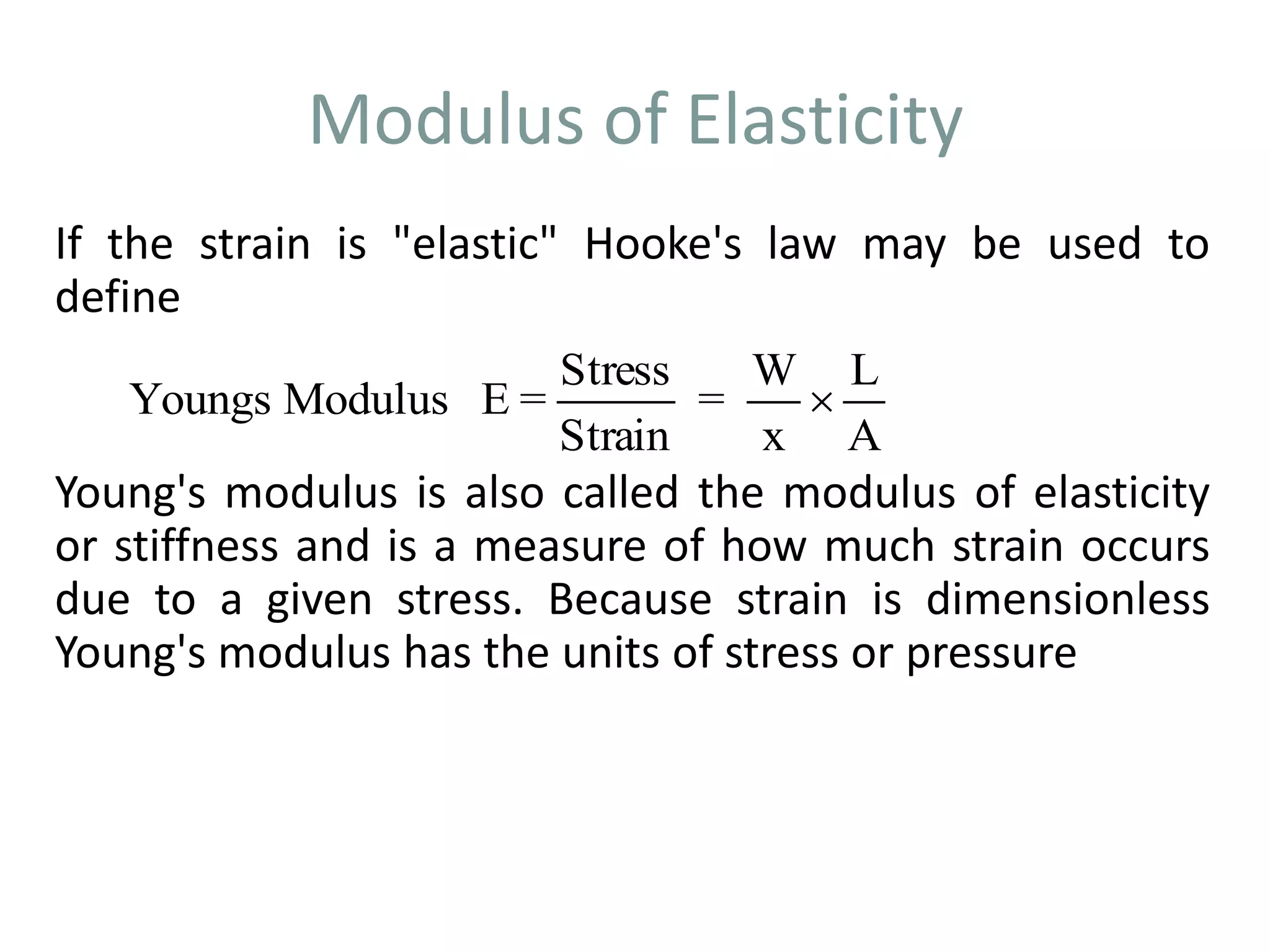
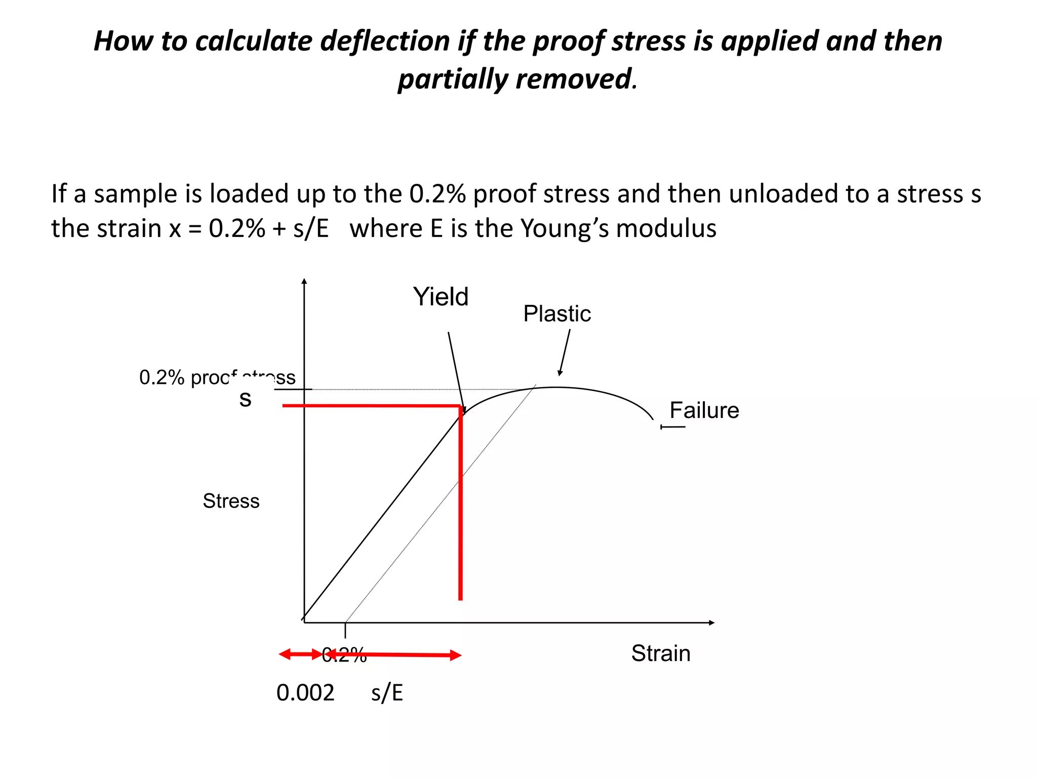
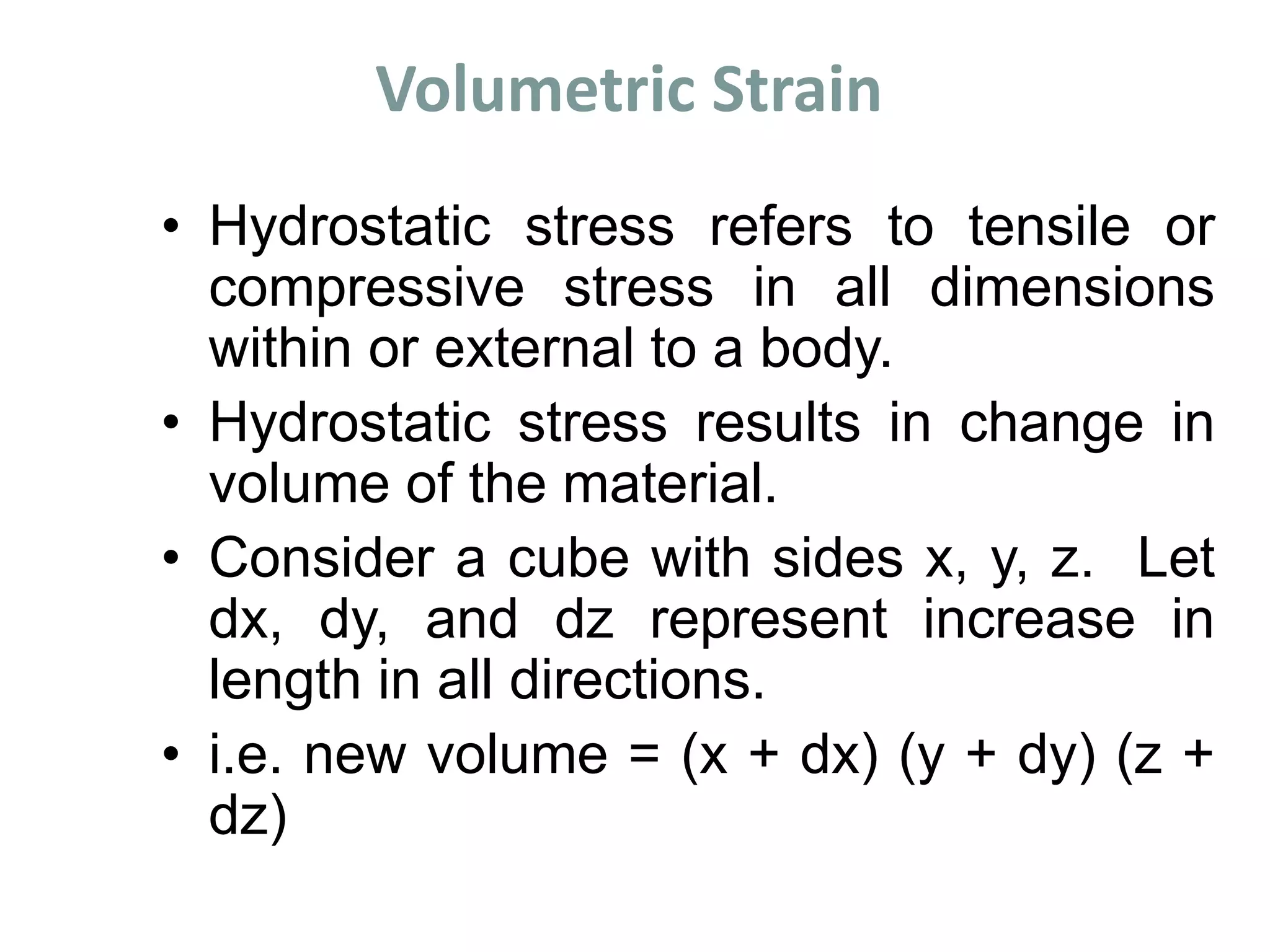
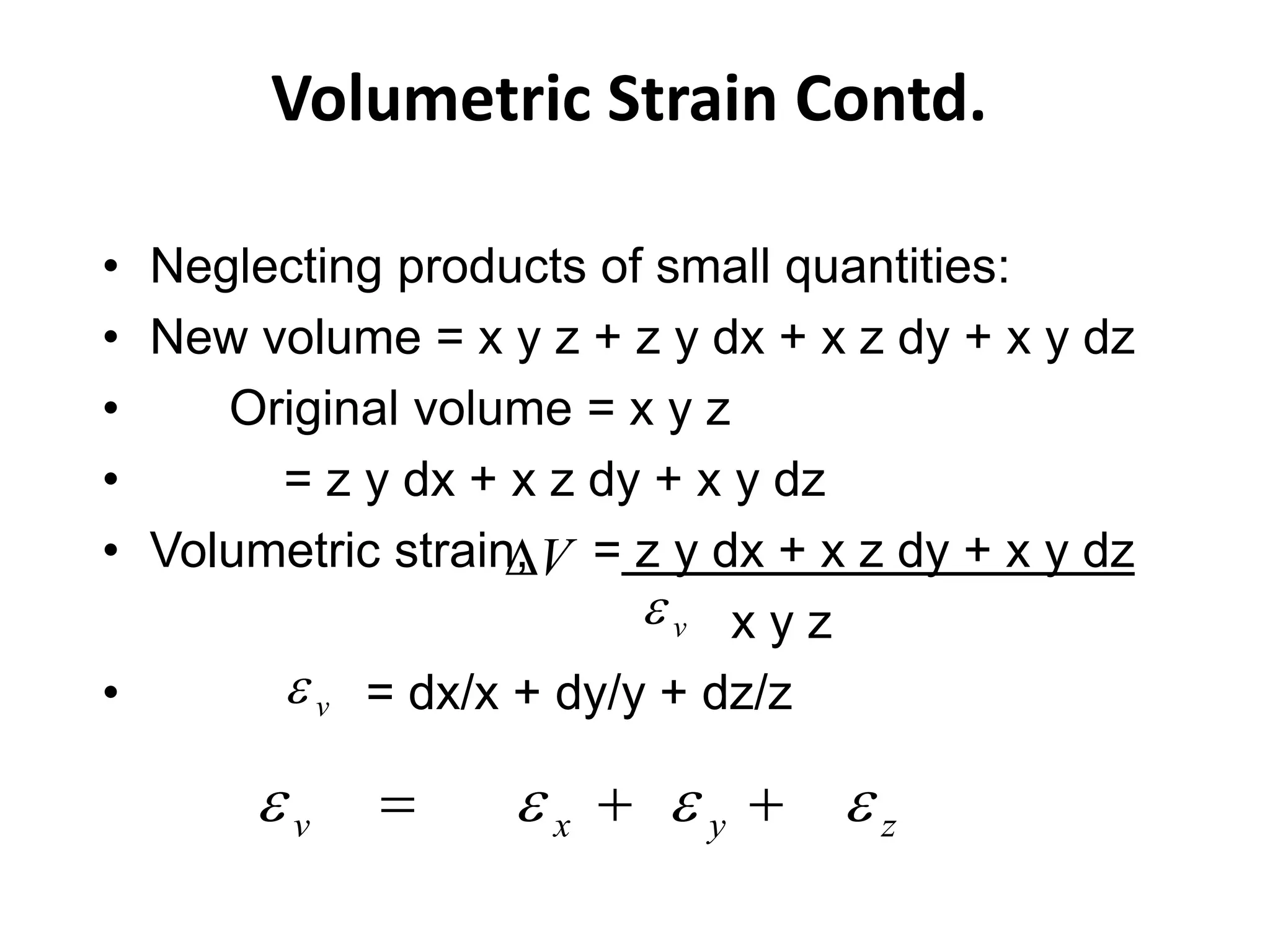
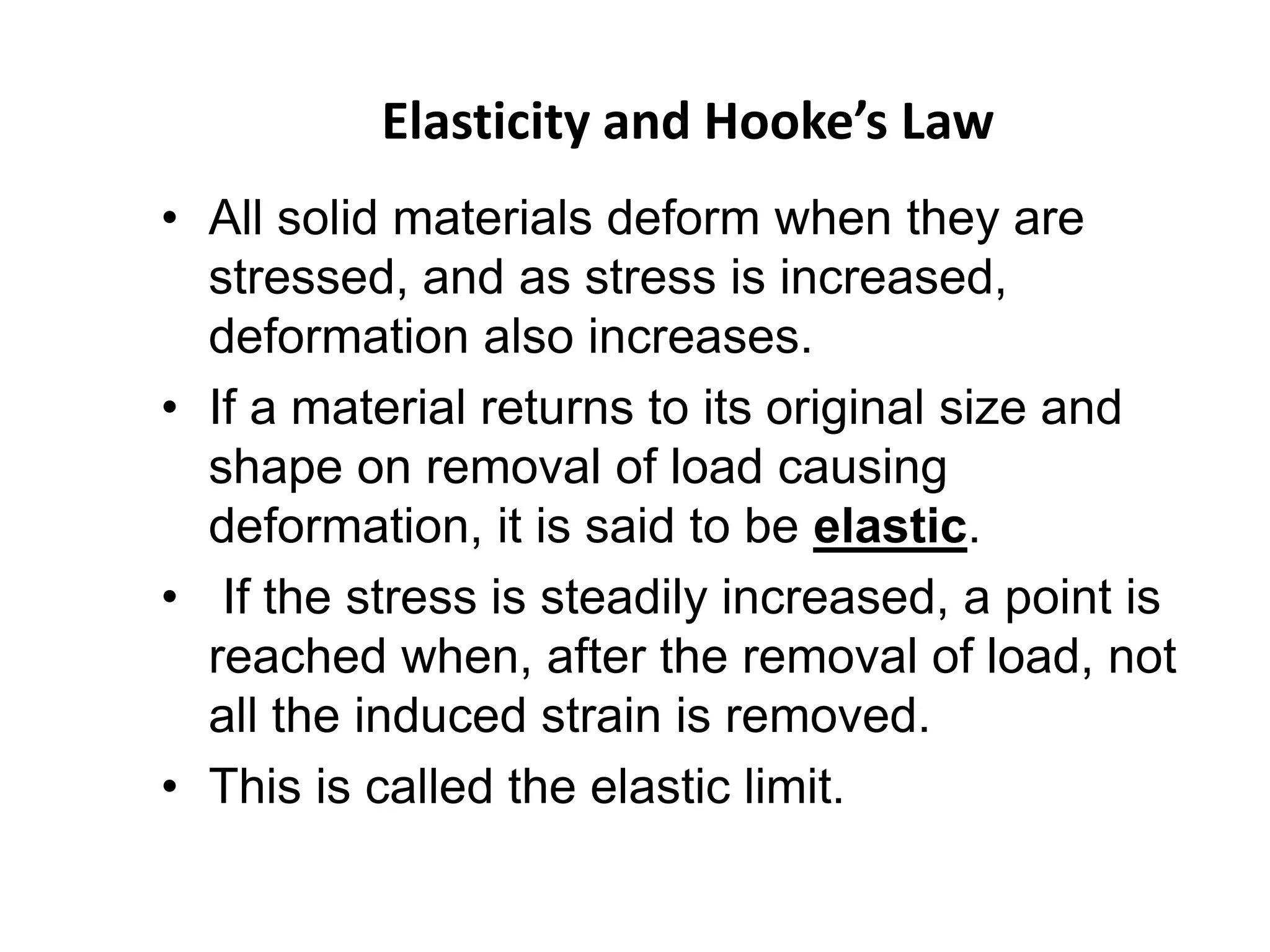
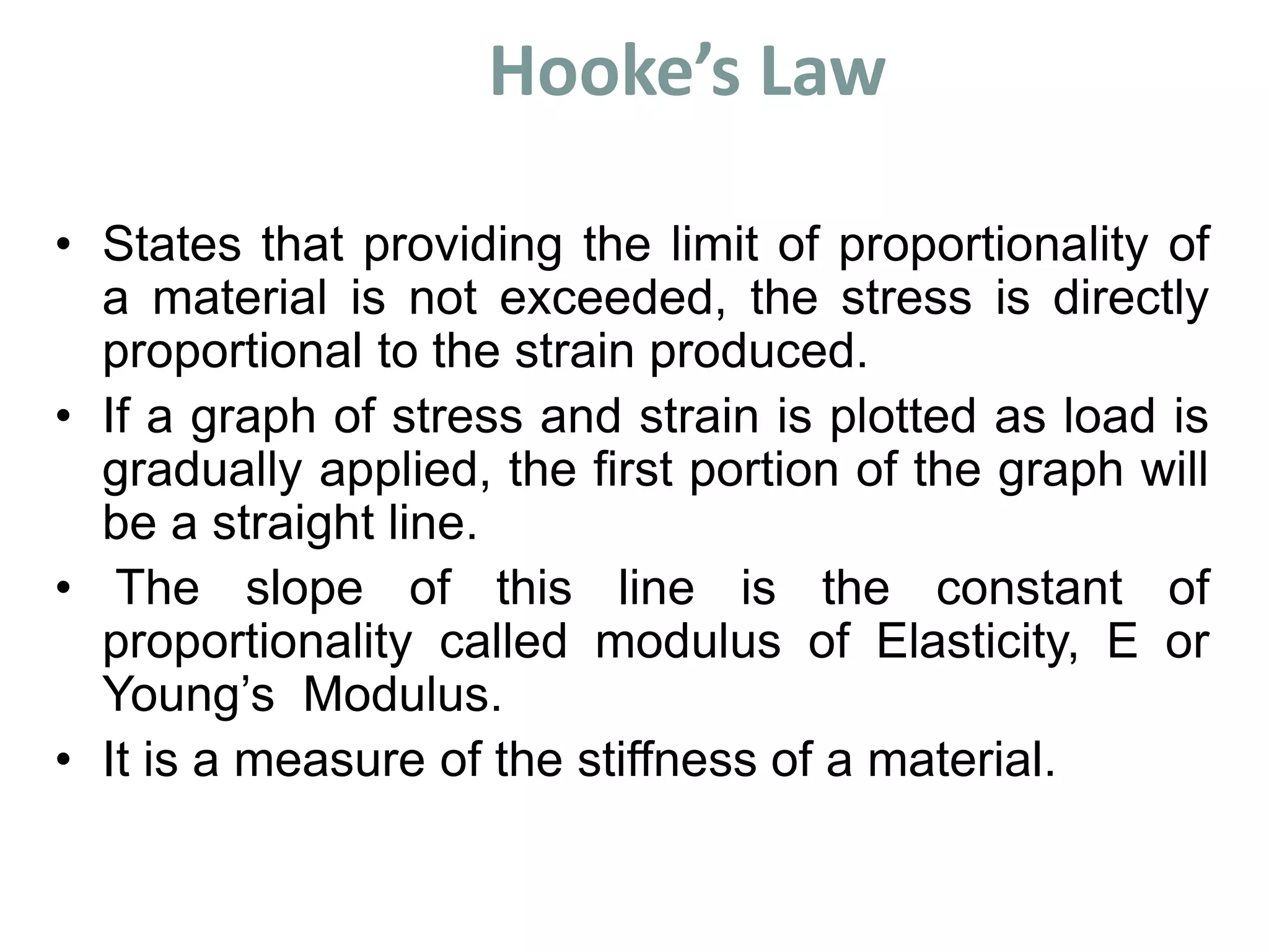
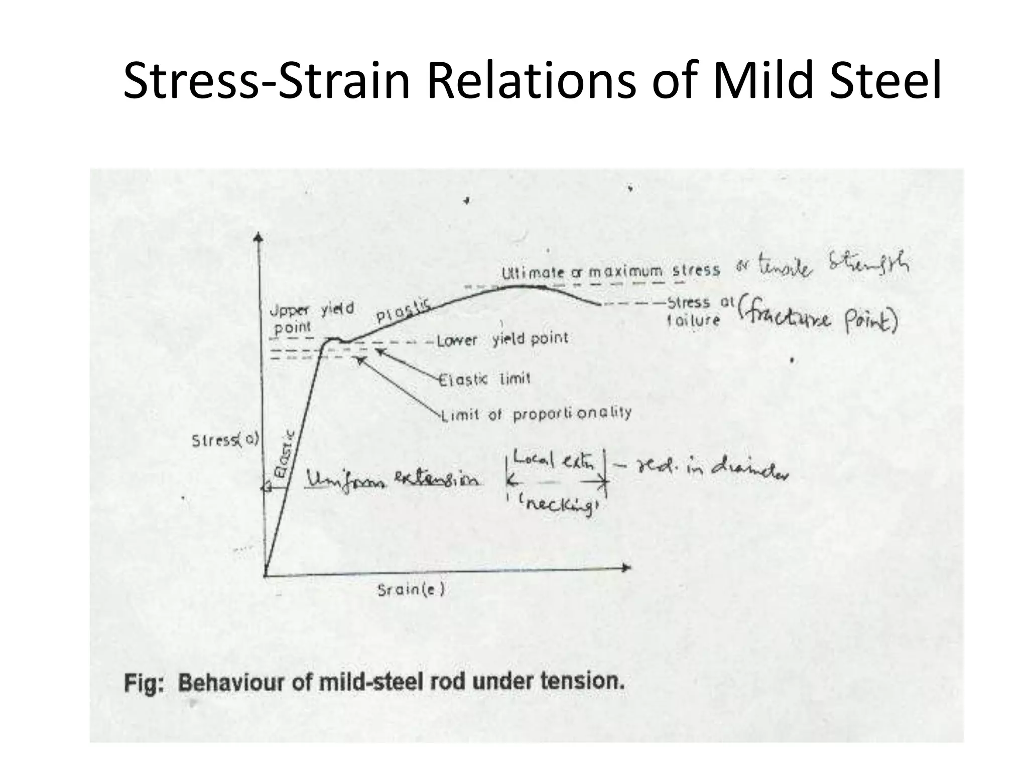
2. Materials deform both elastically and plastically when stressed. Elastic deformation is reversible but plastic deformation causes a permanent change in shape. Hooke's law describes the linear elastic behavior of many materials, where stress is directly proportional to strain up to the elastic limit.
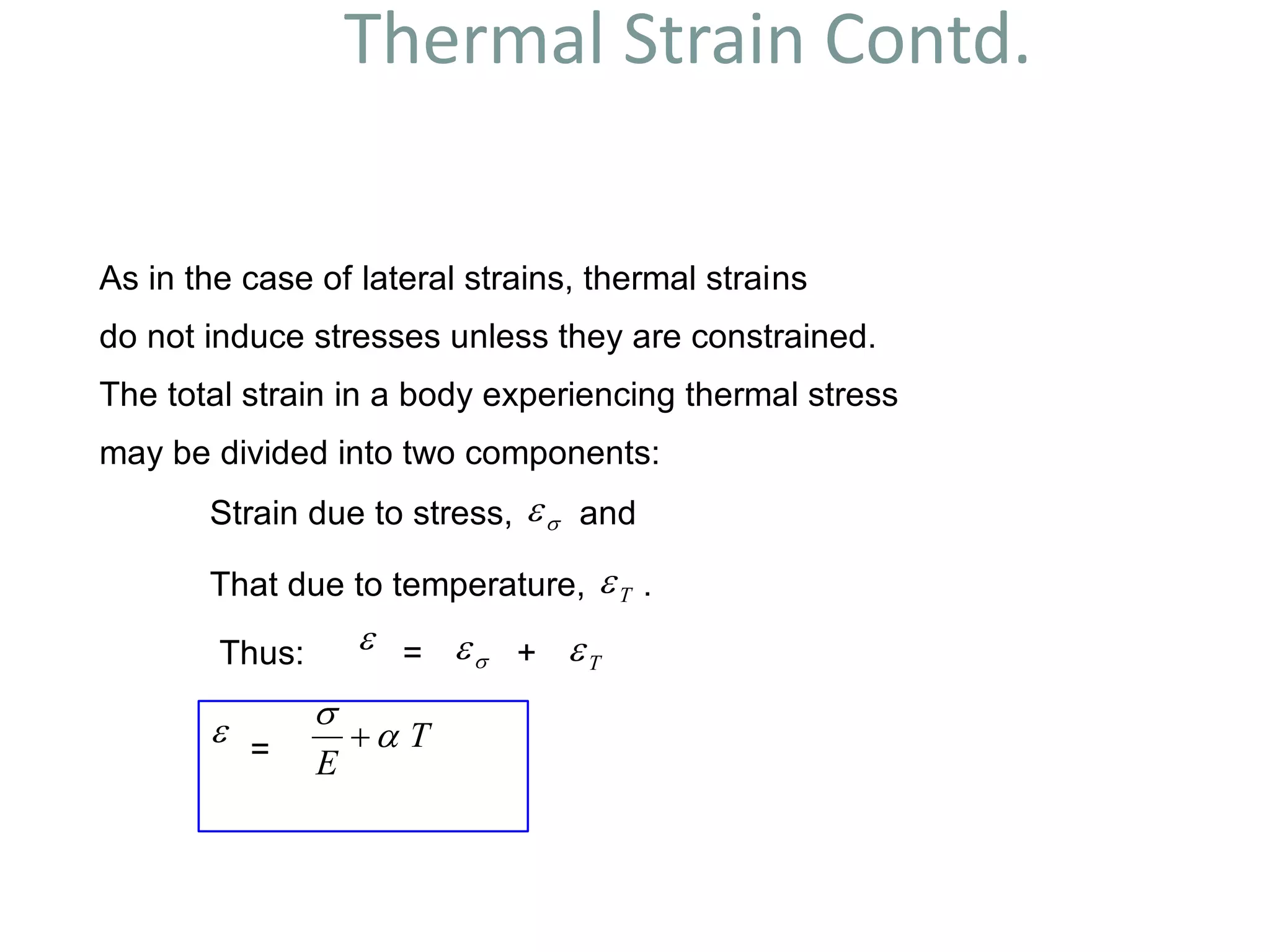
3. Thermal expansion and contraction can induce stress in materials as temperature changes unless deformation is unconstrained. The total strain is the sum of strain due to stress and strain due to temperature changes.


![Temperature Stresses Contd.
Free expansions in bars (1) and (2) are L T and L T 1 2 respectively.
Due to end fixing force, F: the decrease in length of bar (1) is
FL
A E1 1
and the increase in length of (2) is
FL
A E2 2
.
At Equilibrium:
L T
FL
A E
L T
FL
A E
i e F
A E A E
T
i e A
A E A E
E E A A
T
T A E E
A E A E
T A E E
A E A E
1
1 1
2
2 2
1 1 2 2
1 2
1 1
2 2 1 1
1 2 1 2
1 2
1
1 2 2 1 2
1 1 2 2
2
1 2 1 1 2
1 1 2 2
1 1
L
NM O
QP
. . [ ] ( )
. . ( )
( )
( )
Note: As a result of Force, F, bar (1) will be in compression while (2) will be in tension.
1 1
2 2
L
(a) L1 T
1
L2 T
2 {b}
FL
A E1 1
F 1 F
F 2 F
(c)
FL
A E2 2](https://image.slidesharecdn.com/somppt-150115230452-conversion-gate01/75/Som-ppt-26-2048.jpg)