Downloaded 106 times


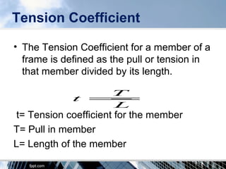
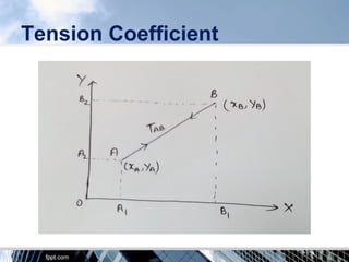

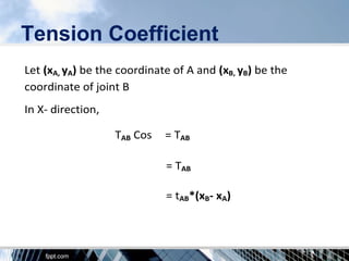
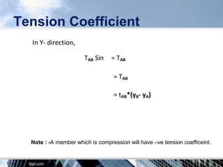
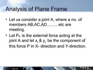
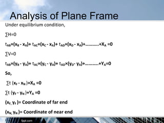
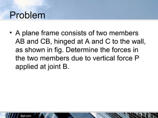
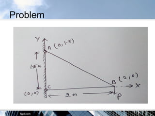
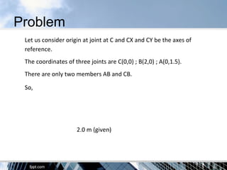
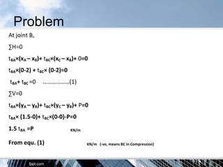
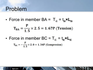
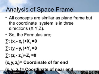
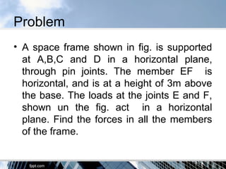
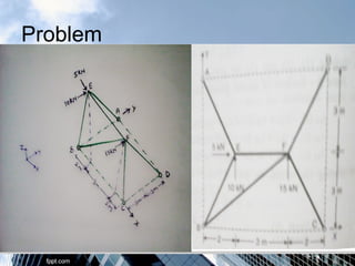
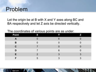

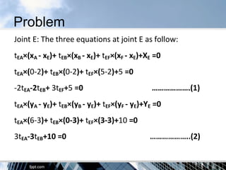
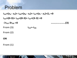
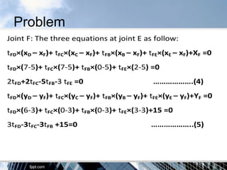
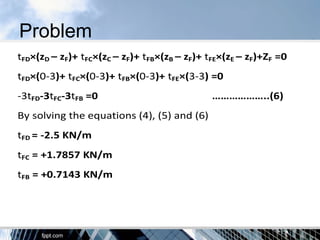
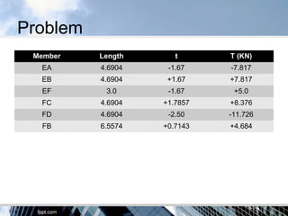


The document discusses the tension coefficient method for analyzing frames. The tension coefficient of a member is defined as the tension in the member divided by its length. Equilibrium equations are written at each joint using the tension coefficients and coordinates of the joints. Examples are provided to demonstrate how to set up and solve the equilibrium equations to determine the tension in each member for both plane and space frames under given loading conditions. Forces in all members of a sample space frame are calculated.


