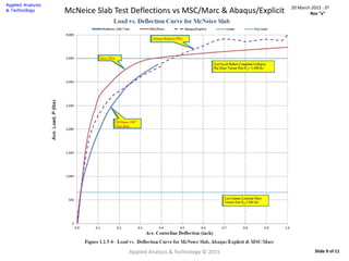
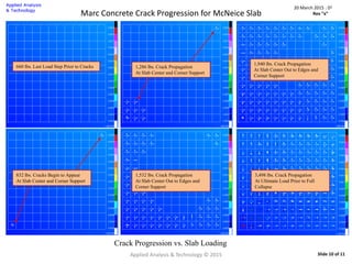
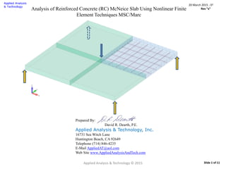
This document presents a nonlinear finite element analysis of a reinforced concrete slab tested by McNeice in 1967. A quarter-symmetric model of the slab was created in MSC/Marc using solid elements for the concrete and truss elements for the rebar. The concrete was modeled using damage plasticity to account for cracking and crushing. Load-deflection curves from the Marc analysis are compared to experimental test data and results from Abaqus. The analysis shows the slab initially cracking around 660 lbs and progressively cracking further until reaching ultimate load at 3,498 lbs. Crack patterns produced by Marc at different load levels are also presented.
![Applied Analysis & Technology © 2015
20 March 2015 : D2
Rev “x”
Slide 8 of 11
Concrete : Isotropic Properties
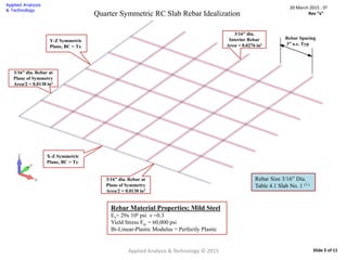
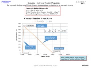
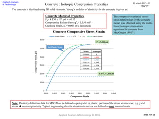
The concrete is idealized using 3D solid elements. Young’s modulus of elasticity for the concrete is given as:
Concrete Material Properties
Elastic : Ee= 4.15 x10⁶ psi ν = 0.15
Cracking : Critical Cracking Stress (Rupture Stress) fr = 460 psi
Softening Modulus, Es= 243,495 psi [Failure Strain = 0.002 in/in]
Crushing Strain, εc = 0.003 in/in, Shear Retention : 20%
Plasticity : Elastic-Plastic, Isotropic Hardening, Buyukozturk Concrete
Concrete Isotropic Material Input Dialog](https://image.slidesharecdn.com/4f9d621c-c684-4177-994c-fa9385c28802-151109184128-lva1-app6892/85/Analysis-McNeice-Slab-MSC-Marc-8-320.jpg)