LINEAR ACCELARATOR
INTROUDUCTION:
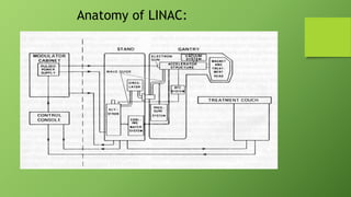
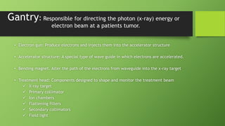
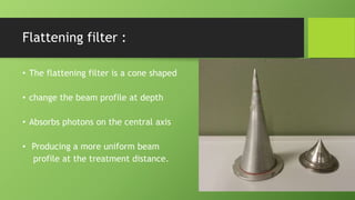
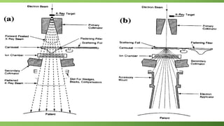
• A linear accelerator is a machine that accelerate the charge
particle to higher energy in to the linear path.
• LINAC therapy allows to deliver higher doses of radiation to the
tumor with limited damage to the surrounding healthy tissue
and/or organs
• Uses higher energies for the treatment of cancer patients.
Anatomy of LINAC:
Vertical mounting (LINAC 1 at AKUH)
Horizontal Mounting (LINAC 2 at AKUH)
Auxiliary system:
It consist of four system that are not involved in
electron acceleration.
• A vacuum pumping system producing a vacuum pressure in the
accelerating guide and the RF generator.
• A water cooling system to accelerating waveguide,RF generator. It
provides stable temperature.
• Air pressure system.
• Shielding against leakage radiation.
Components:
• Modulator cabinet
• Console control
• Drive stand
• Gantry
• Treatment couch
• Other accessories
Modulator cabinet:
• It distribute primary electrical power and high voltage to
magnetron and klystron
• it located in treatment room
• it major components
 The fan control: need arises for cooling the power distribution
 Auxiliary system: contains the emergency off button
 Primary power dist: Primary power-distribution system
Console control:
• Monitoring and controlling the LINAC
• All interlocks checks to allow beam started
• Provide digital display of monitor units
• Mechanical beam parameters
Drive Stand:
• Klystron/Magnetron: power source used to generate
electromagnetic waves for the accelerator guides
• Waveguide: hollow tube-like structure that guide the
electromagnetic waves from the magnetron to the accelerating guide
where electrons are accelerated
• Circulator: connects between the klystron/magnetron and
waveguide that prevents any reflected microwaves.
• Water-cooling system: allows many components in the gantry and
drive stand to operate at a constant temperature
Magnetron:
Device that
provides high-
frequency
microwave
Accelerate
the electrons
into the
accelerating
waveguide.
Preferred for
lower energies
<=6
Source of
microwave
about 3000
MHZ
Klystron:
• Source of microwave radio frequency RF
• Also microwave amplifier
• To accelerate the electron into waveguide
• For megavoltage energies >6MV
Electron gun:
• source of electrons; it is essentially a simple electrostatic
accelerator called an electron gun.
• Two types of electron gun are in use as sources of electrons in
medical linacs.
• — Diode type;
• — Triode type.
Beam transport system:
To transport electrons from accelerating waveguide to the x-ray
target.
• Bending magnet
90 degree bending
270 degree bending
• Steering coils
• Focusing coils
Diagram:
Gantry: Responsible for directing the photon (x-ray) energy or
electron beam at a patients tumor.
• Electron gun: Produce electrons and injects them into the accelerator structure
• Accelerator structure: A special type of wave guide in which electrons are accelerated.
• Bending magnet. Alter the path of the electrons from waveguide into the x-ray target
• Treatment head: Components designed to shape and monitor the treatment beam
 X-ray target
 Primary collimator
 Ion chambers
 Flattening filters
 Secondary collimators
 Field light
Treatment Head Diagram:
X-ray target:
• High z material tungsten
• It thickness maximize the x-ray output and minimize electron
contamination
Primary collimators Secondary collimators:
• Fixed just beyond the x-ray target
• Design to limit maximum field size
• It absorbs scatter from the target
• Place Away from the x-ray target
• Secondary collimators are
typically independent jaws
• It allow the field to be shaped into a
variety of rectangular shapes.
• There are two sets of jaws higher jaws
(y-axis) lower jaws (x-axis)
• independent jaws to perform dynamic
wedging.
Flattening filter :
• The flattening filter is a cone shaped
• change the beam profile at depth
• Absorbs photons on the central axis
• Producing a more uniform beam
profile at the treatment distance.
Scattering Foils:
• Typically consist of dual lead foils.
• To ensure minimize the bremsstrahlung x-rays
• narrow beam is usually spread by two scattering foils
• This converts the beam from a pencil beam to a usable wide beam
Ionization chambers:
• Ionization chambers embedded in linac clinical x-rays and
electrons for dose monitoring for safety of the patients
• Two separately ion chambers
• It position between the flattening filters or scattering foils and
secondary collimators
Dose monitoring:
• For patient safety, the linac have two electrodes to monitor beam
output and connected to the counter.
• If the primary chamber fails during patient treatment, the
secondary chamber will terminate the irradiation.
• only a few per cent above the prescribed dose has been delivered.
• The beam energy, flatness and symmetry.
Multi Leaf Collimator (MLC):
• Used to define any field shape for radiation
beams
• The number of leaves in commercial models
with 120 leaves (60 pairs) covering fields up to
40 × 40 cm2
• MLCs are becoming valuable in supplying
intensity modulated fields in conformal
radiotherapy, either in the step and shoot mode
or in a continuous dynamic mode.
Field light and lasers:
• It is a Field localizing device.
• Used to display the position of the radiation field on the patient
skin.
• The accuracy of the laser guides in determining isocentre position
• Tolerance of laser position is 2 mm
Other accessories:
• Custom Blocks:
 In the event that MLCs are unable to produce the desired field shape. They are
limited by their cost, weight, and time issues
• Electron Cone and Electron Cutout:
 The electron cone attenuates electrons that are scattered outside of the
required beam shape before they reach the cutout
• Electronic portal imaging:
 Electronic portal imaging refers to an electronic detector replacing the
radiographic film
 Provides feedback on single-event setup accuracy or observation of treatment
in near real-time
 the patient can be repositioned before treatment takes place.
Patients supports:
• Treatment couch: mounted on a rotational axis around the
isocenter Also called patient support assembly (PSA)
• Immobilization devices
THANK YOU ...

LINEAR ACCELARATOR

  • 1.
  • 2.
    INTROUDUCTION: • A linearaccelerator is a machine that accelerate the charge particle to higher energy in to the linear path. • LINAC therapy allows to deliver higher doses of radiation to the tumor with limited damage to the surrounding healthy tissue and/or organs • Uses higher energies for the treatment of cancer patients.
  • 3.
  • 4.
  • 5.
  • 6.
    Auxiliary system: It consistof four system that are not involved in electron acceleration. • A vacuum pumping system producing a vacuum pressure in the accelerating guide and the RF generator. • A water cooling system to accelerating waveguide,RF generator. It provides stable temperature. • Air pressure system. • Shielding against leakage radiation.
  • 7.
    Components: • Modulator cabinet •Console control • Drive stand • Gantry • Treatment couch • Other accessories
  • 8.
    Modulator cabinet: • Itdistribute primary electrical power and high voltage to magnetron and klystron • it located in treatment room • it major components  The fan control: need arises for cooling the power distribution  Auxiliary system: contains the emergency off button  Primary power dist: Primary power-distribution system
  • 9.
    Console control: • Monitoringand controlling the LINAC • All interlocks checks to allow beam started • Provide digital display of monitor units • Mechanical beam parameters
  • 10.
    Drive Stand: • Klystron/Magnetron:power source used to generate electromagnetic waves for the accelerator guides • Waveguide: hollow tube-like structure that guide the electromagnetic waves from the magnetron to the accelerating guide where electrons are accelerated • Circulator: connects between the klystron/magnetron and waveguide that prevents any reflected microwaves. • Water-cooling system: allows many components in the gantry and drive stand to operate at a constant temperature
  • 11.
    Magnetron: Device that provides high- frequency microwave Accelerate theelectrons into the accelerating waveguide. Preferred for lower energies <=6 Source of microwave about 3000 MHZ
  • 12.
    Klystron: • Source ofmicrowave radio frequency RF • Also microwave amplifier • To accelerate the electron into waveguide • For megavoltage energies >6MV
  • 13.
    Electron gun: • sourceof electrons; it is essentially a simple electrostatic accelerator called an electron gun. • Two types of electron gun are in use as sources of electrons in medical linacs. • — Diode type; • — Triode type.
  • 14.
    Beam transport system: Totransport electrons from accelerating waveguide to the x-ray target. • Bending magnet 90 degree bending 270 degree bending • Steering coils • Focusing coils
  • 15.
  • 16.
    Gantry: Responsible fordirecting the photon (x-ray) energy or electron beam at a patients tumor. • Electron gun: Produce electrons and injects them into the accelerator structure • Accelerator structure: A special type of wave guide in which electrons are accelerated. • Bending magnet. Alter the path of the electrons from waveguide into the x-ray target • Treatment head: Components designed to shape and monitor the treatment beam  X-ray target  Primary collimator  Ion chambers  Flattening filters  Secondary collimators  Field light
  • 17.
  • 18.
    X-ray target: • Highz material tungsten • It thickness maximize the x-ray output and minimize electron contamination
  • 19.
    Primary collimators Secondarycollimators: • Fixed just beyond the x-ray target • Design to limit maximum field size • It absorbs scatter from the target • Place Away from the x-ray target • Secondary collimators are typically independent jaws • It allow the field to be shaped into a variety of rectangular shapes. • There are two sets of jaws higher jaws (y-axis) lower jaws (x-axis) • independent jaws to perform dynamic wedging.
  • 20.
    Flattening filter : •The flattening filter is a cone shaped • change the beam profile at depth • Absorbs photons on the central axis • Producing a more uniform beam profile at the treatment distance.
  • 21.
    Scattering Foils: • Typicallyconsist of dual lead foils. • To ensure minimize the bremsstrahlung x-rays • narrow beam is usually spread by two scattering foils • This converts the beam from a pencil beam to a usable wide beam
  • 23.
    Ionization chambers: • Ionizationchambers embedded in linac clinical x-rays and electrons for dose monitoring for safety of the patients • Two separately ion chambers • It position between the flattening filters or scattering foils and secondary collimators
  • 24.
    Dose monitoring: • Forpatient safety, the linac have two electrodes to monitor beam output and connected to the counter. • If the primary chamber fails during patient treatment, the secondary chamber will terminate the irradiation. • only a few per cent above the prescribed dose has been delivered. • The beam energy, flatness and symmetry.
  • 25.
    Multi Leaf Collimator(MLC): • Used to define any field shape for radiation beams • The number of leaves in commercial models with 120 leaves (60 pairs) covering fields up to 40 × 40 cm2 • MLCs are becoming valuable in supplying intensity modulated fields in conformal radiotherapy, either in the step and shoot mode or in a continuous dynamic mode.
  • 26.
    Field light andlasers: • It is a Field localizing device. • Used to display the position of the radiation field on the patient skin. • The accuracy of the laser guides in determining isocentre position • Tolerance of laser position is 2 mm
  • 27.
    Other accessories: • CustomBlocks:  In the event that MLCs are unable to produce the desired field shape. They are limited by their cost, weight, and time issues • Electron Cone and Electron Cutout:  The electron cone attenuates electrons that are scattered outside of the required beam shape before they reach the cutout • Electronic portal imaging:  Electronic portal imaging refers to an electronic detector replacing the radiographic film  Provides feedback on single-event setup accuracy or observation of treatment in near real-time  the patient can be repositioned before treatment takes place.
  • 28.
    Patients supports: • Treatmentcouch: mounted on a rotational axis around the isocenter Also called patient support assembly (PSA) • Immobilization devices
  • 29.