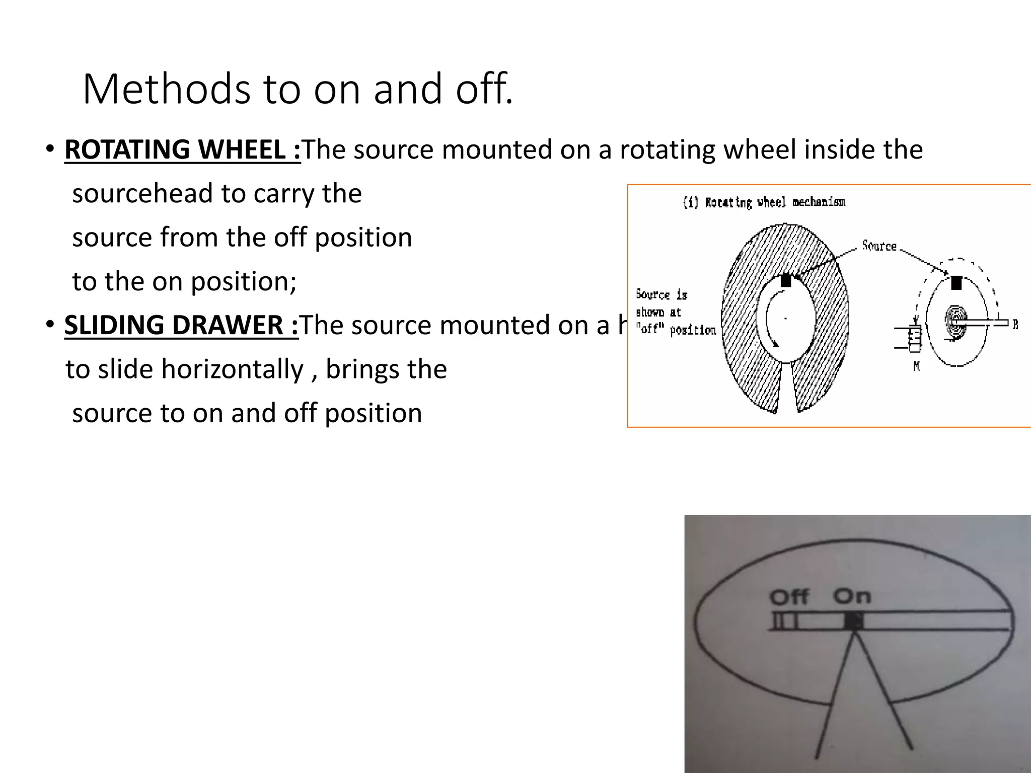
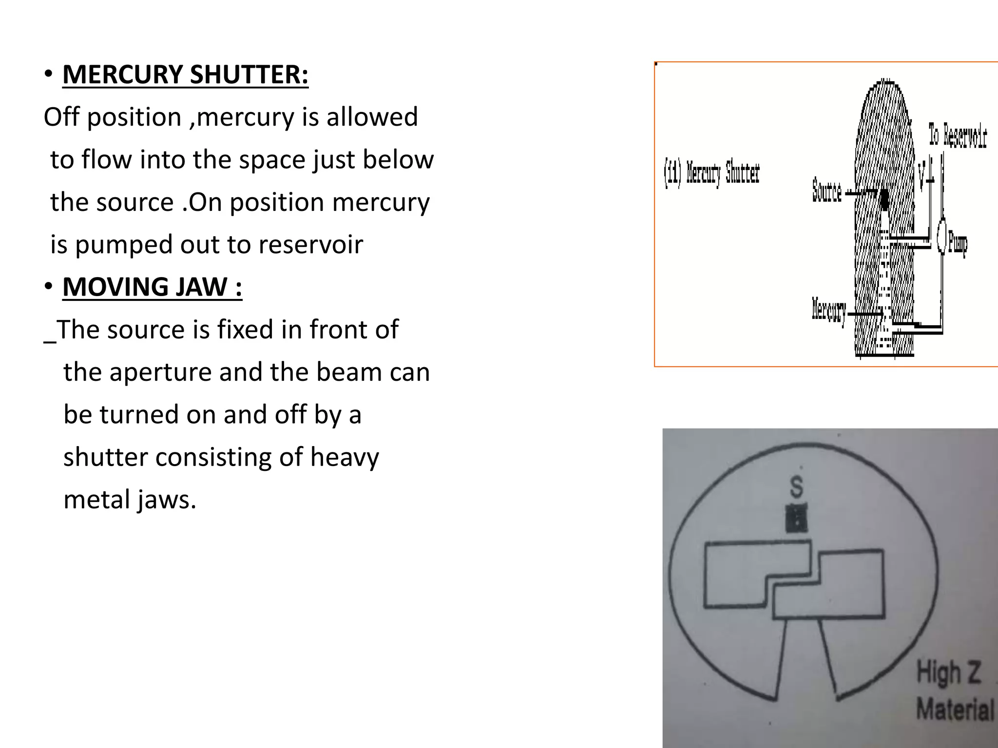
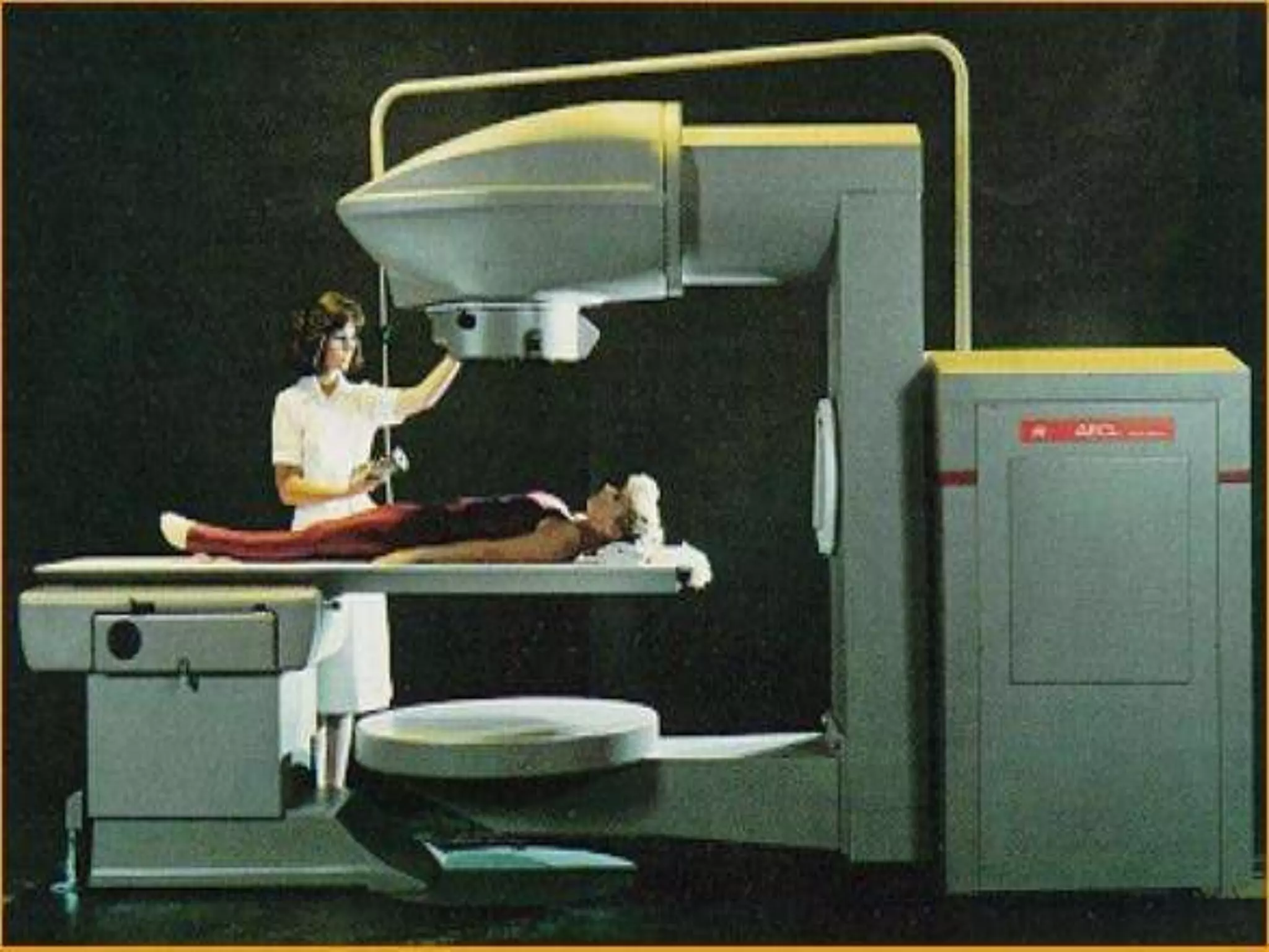
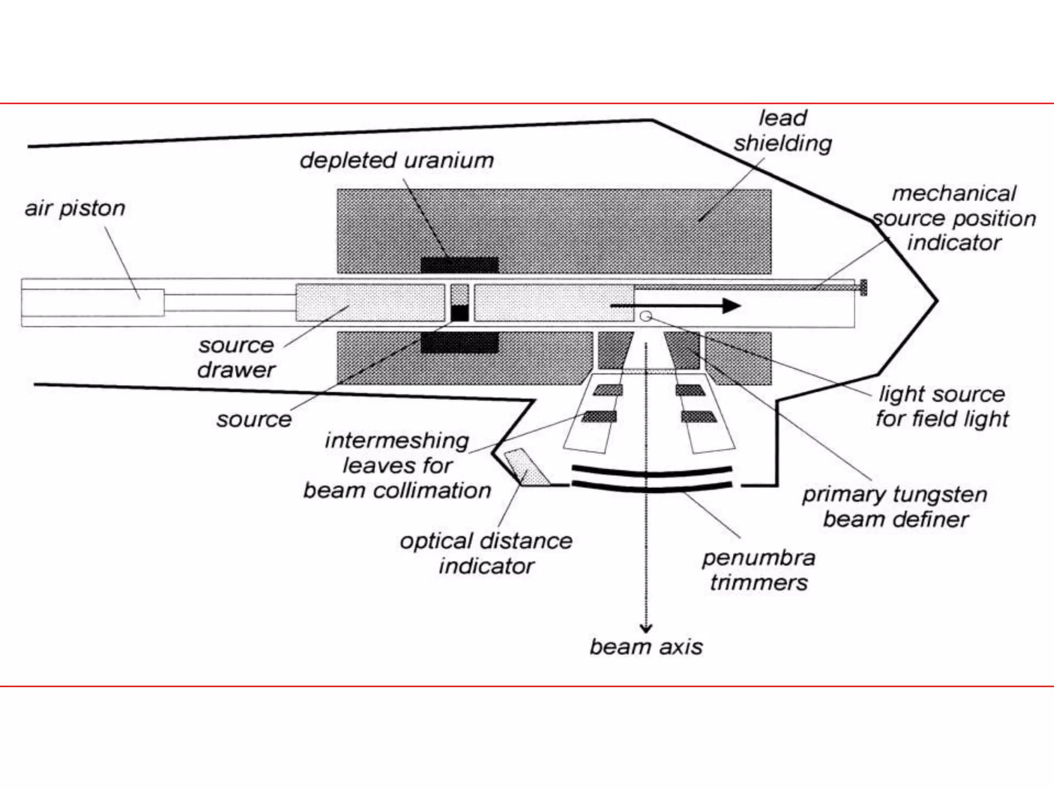
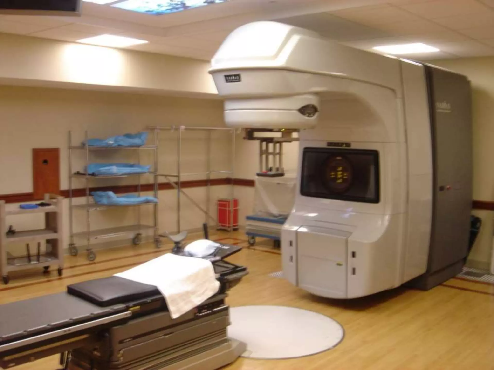
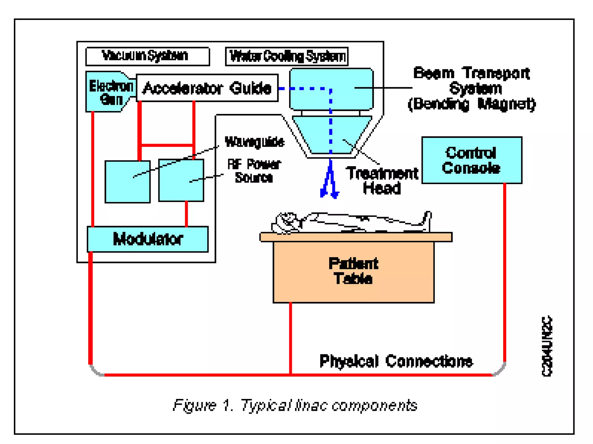
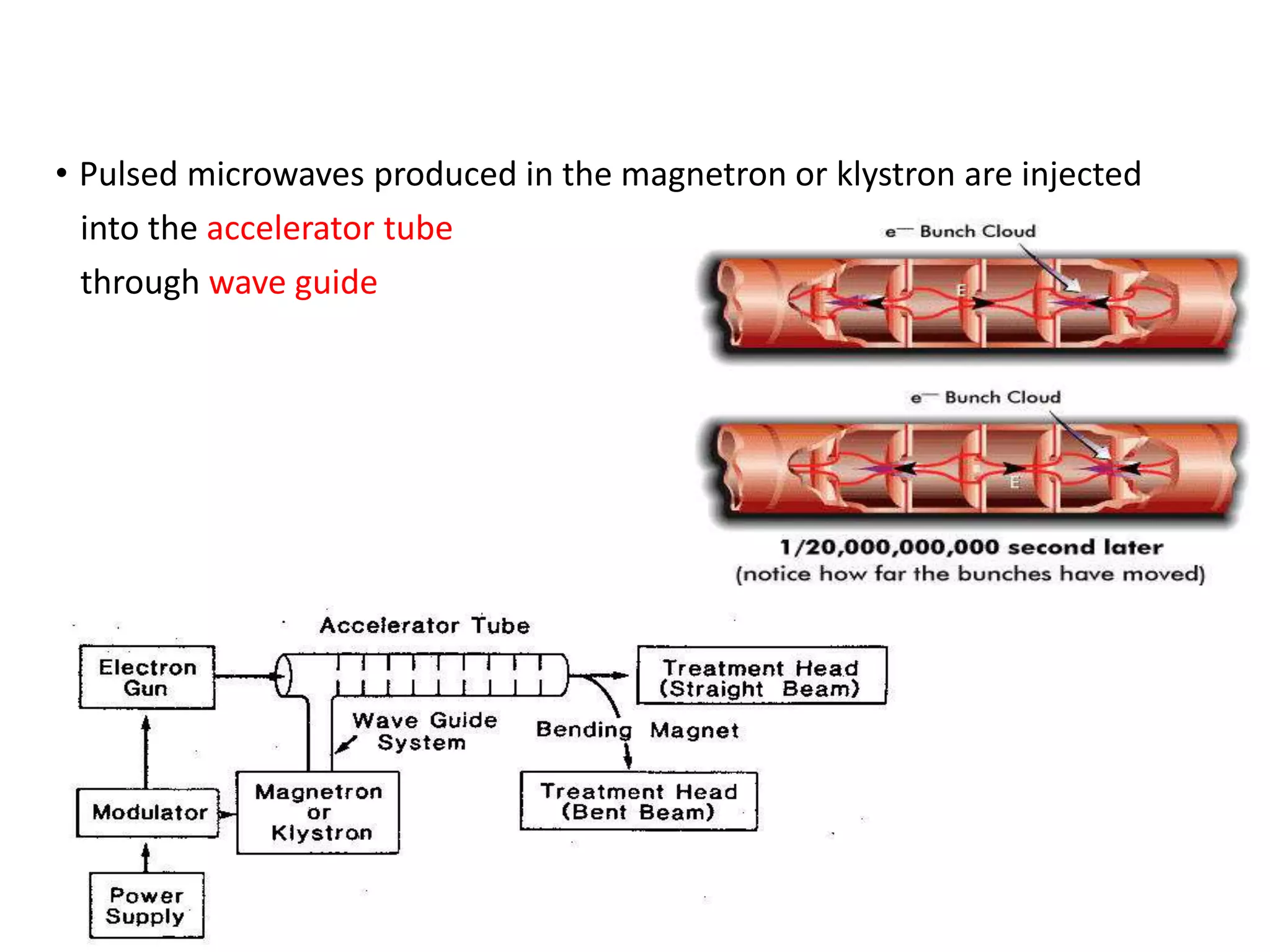
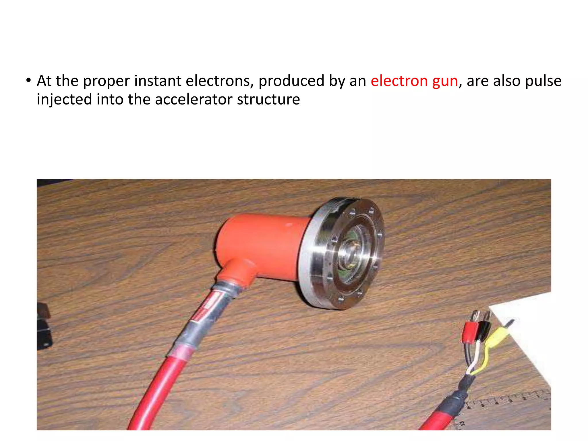
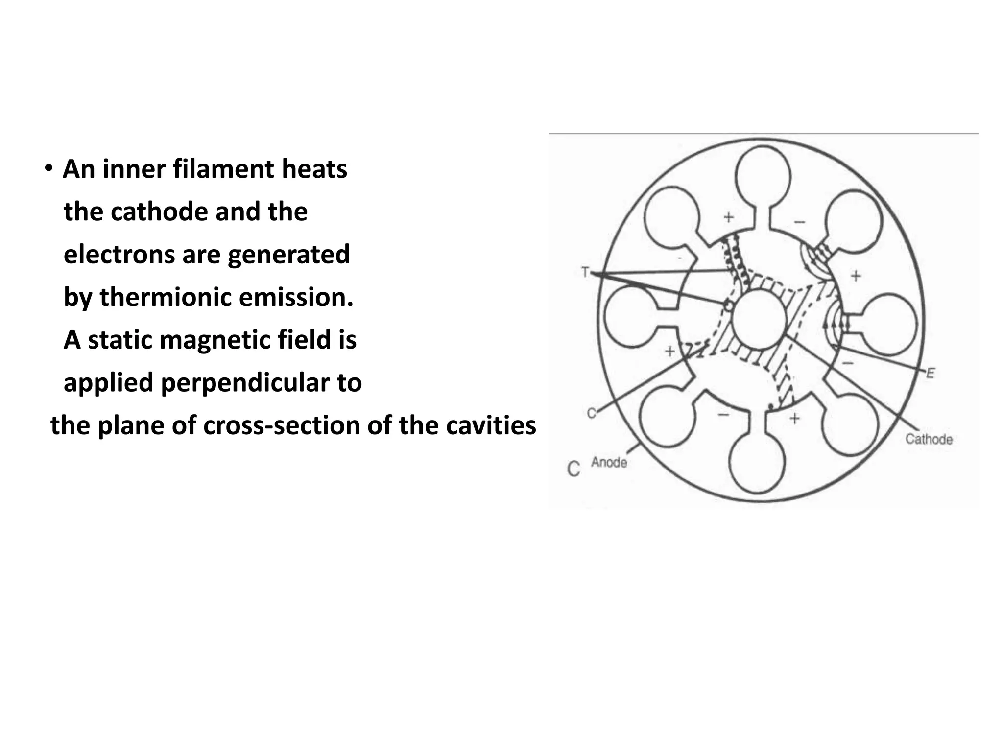
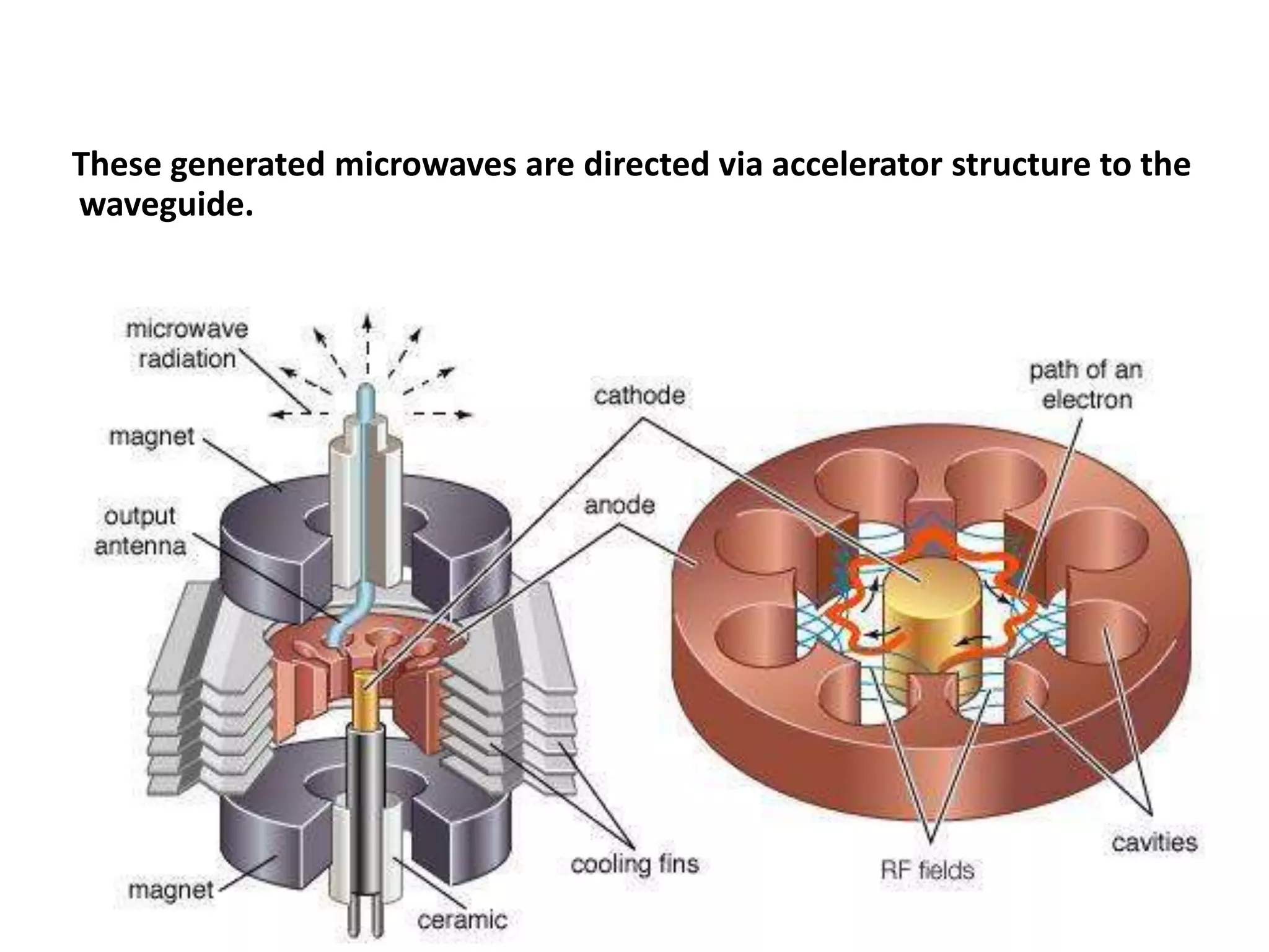
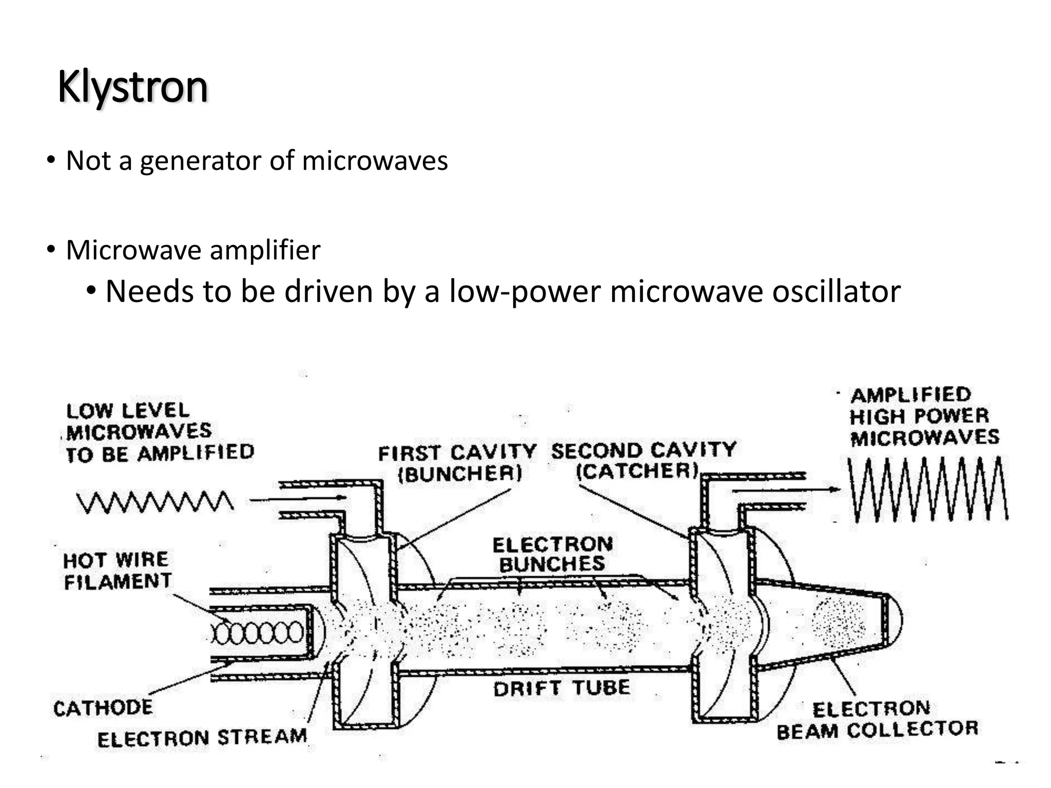
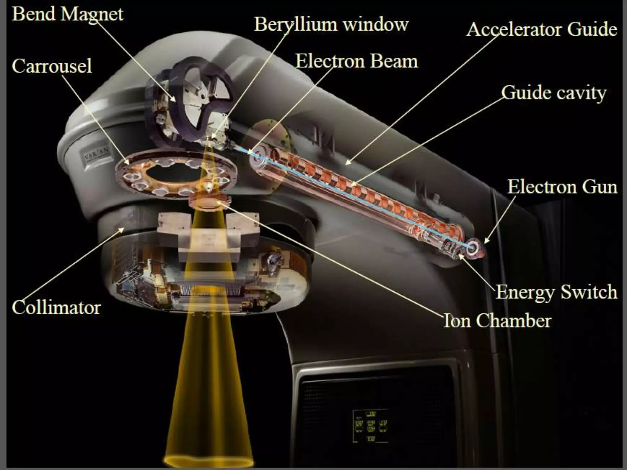
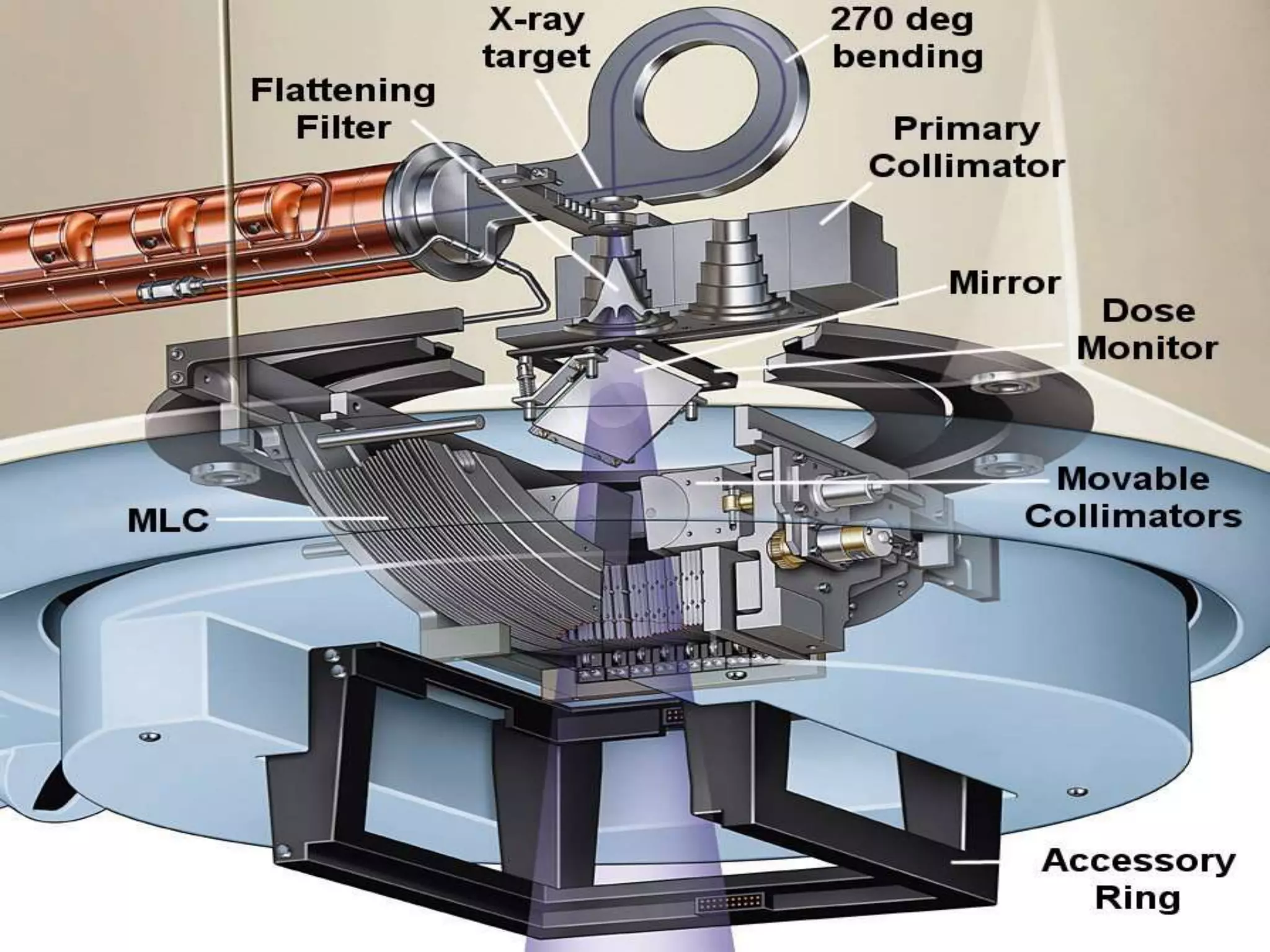
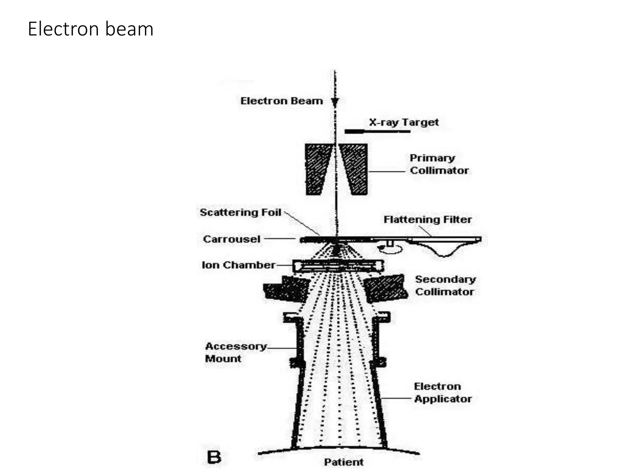
TElETHERAPY
MACHINES
LINAC &
TELECOBALT
KIRAN KUMAR BR
TELETHERAPY
TREATMENT IN WHICH THE SOURCE OF THE
THERAPEUTIC AGENT (SUCH AS RADIATION)
IS AT A DISTANCE FROM BODY
Tele-Distant Therapeia-Treatment
• Teletherapy, used to treat various form of cancer.
• This method uses focused beam of X-ray radiation or gamma rays generated
by such machines as linear accelarator, cobalt machine or gamma knife.
• Radiotherapy is one of the major modalities of cancer treatment and every
alternate cancer patient will require radiation during the course of
treatment.
• It is also well recognized that over 40% of
the course of cancer result directly from the use of radiotherapy.
• 2020, 70% of the global need for radiotherapy will be in the currently
defined developing world.
COBALT-60
• In 1951, Cobalt 60 teletherapy was first put to clinical use in London
The main reasons for its suitability for teletherapy
• Availability of relatively small
• High specific activity
• Sources that minimise the beam penumbra
• Relatively long half-life (5.27 years)
• Almost monochromatic high-energy photon emission(photons of 1.173 MeV
and 1.333 MeV in equal quantity).
•collimator
• gantry
• couch
SOURCE
• The 60Co source is produced by irradiating ordinary stable 59Co with neutrons
in a reactor.
• Nuclear reaction can be represented by 59Co(n,γ) 60Co.
• 60Co source, solid cylinder, discs, or pallets, contained inside a stainless-
steel capsule and sealed by welding.
• This capsule is placed into another steel capsule which is again sealed
by welding.
• The double-welded seal is necessary to prevent any leakage of the
radioactive material
• 60Co source decays to 60Ni with the emission of β particles (Emax = 0.32
MeV) and two photons per disintegration of energies 1.17 and 1.33 MeV .
• These γ rays constitute treatment beam.
• Cobalt-60 Gamma radiation typically has energy of about 1.2MV,
• D-max being 0.5 cm. and a percentage depth of 55% at 10 cm.
• The β particles are absorbed in the cobalt metal and the stainless-steel
capsules resulting in the emission of bremsstrahlung x-rays and a small
amount of characteristic x-rays.
• A typical teletherapy 60 CO source is a cylinder of diameter 1 to 2 cm, height
5 cm,
• positioned in the Cobalt Unit with the circular
end facing the patient.
• The fact that the radiation source is not a point source complicates the beam
geometry and gives rise to what is known as the geometric penumbra
SOURCE HOUSING
• The housing for the source is called the source head .
• It consists of a steel shell filled with lead for shielding purposes and a device
for bringing the source in front of an opening in the head from which the
useful beam emerges.
• A heavy metal alloy sleeve is provided to form an additional primary shield
when the source is in the off position.
Methods to on and off.
• ROTATING WHEEL :The source mounted on a rotating wheel inside the
sourcehead to carry the
source from the off position
to the on position;
• SLIDING DRAWER :The source mounted on a heavy metal drawer ,its ability
to slide horizontally , brings the
source to on and off position
• MERCURY SHUTTER:
Off position ,mercury is allowed
to flow into the space just below
the source .On position mercury
is pumped out to reservoir
• MOVING JAW :
The source is fixed in front of
the aperture and the beam can
be turned on and off by a
shutter consisting of heavy
metal jaws.
Picture of a Co source change
Beam Collimation
• A collimator system is designed to vary the size and shape of the
beam to meet the individual treatment requirements.
• The simplest form of a continuously adjustable diaphragm consists of
two pairs of heavy metal blocks. Each pair can be moved
independently to obtain a square or a rectangle-shaped field.
• If the inner surface of the blocks is made parallel to the central axis of
the beam, the radiation will pass through the edges of the collimating
blocks resulting in what is known as the transmission penumbra.
liMITATION OF TELECOBALT
• poorer geometrical precision
• larger penumbra
• greater mechanical inaccuracy.
• cobalt beams are less penetrating than those from linacs
• They are not adequate for treatment of deep seated tumours
• decreasing output with decay of source
Control area of a 60-Co unit
LINEAR ACCELERATOR
LINEAR ACCELERATOR
• From the technology of World War II,
radars came the ability to produce high energy microwaves.
• This field advanced with the development of high energy microwave tubes
known as
Klystrons or Magnetrons which are still at the heart of todays' modern Linear
Accelerators.
• The First medical Linear Accelerator was created and used in England
in 1953
• Varian, Siemens and Elekta are the Major Producers
• Varian is the first company introduced this product
• Use high frequency electromagnetic waves to acelerate charged
particles (e.g. electrons) to high energies through a linear tube
• High-energy electron beam – treating superficial tumors
• X-rays – treating deep-seated tumors
• Linacs are classified according to their energy levels.
• Low-energy units produce 4- or 6-megavolt (MV) photons
• medium-energy units produce photons of 8 to 10 MV
•
• electron beams of 9 to 15 million electron volts (MeV),
• High-energy linacs produce photons between 15 and 25 MV and
have electron energies ranging from 4 to 22 MeV.
Linear Component
a. The Magnetron or The Klystron
b. The Linac X-ray Beam
c. The Electron Beam
d. Treatment Head
e. Target and Flattening Filter& scattering foil
f. Beam Collimation and Monitoring
g. Gantry
A block diagram of typical medical linear accelerator
• A power supply provides direct current (DC) power to the modulator,
which includes the pulse-
forming network and a
switch tube known as
hydrogen thyratron
These pulses are delivered to the magnetron or klystron and simultaneously
to the electron gun.
• Pulsed microwaves produced in the magnetron or klystron are injected
into the accelerator tube
through wave guide
• At the proper instant electrons, produced by an electron gun, are also pulse
injected into the accelerator structure
• The accelerator structure (or accelerator waveguide) consists of a copper
tube with its interior divided by copper discs or diaphragms of varying
aperture and spacing. This section is evacuated to a high vacuum.
• As the electrons are injected into the accelerator structure with an initial
energy
• The electrons interact with the electromagnetic field of the microwaves
• The electrons gain energy from the sinusoidal electric field by an
acceleration process
• As the high-energy electrons emerge from the exit window of the
accelerator
• They are in the form of a pencil beam of about 3 mm in diameter.
• In low-energy linacs (up to 6 MV) with relatively short accelerator tubes, the
electrons are allowed to proceed straight on and strike a target for x-ray
production.
• In the higher-energy linacs, however, the accelerator structure is too long
• Therefore, is placed horizontally or at an angle with respect to the
horizontal.
• The electrons are then bent through a suitable angle (usually about 90 or
270 degrees) between the accelerator structure and the target.
• The bending of the electron beam is accomplished by a bending magnets,
focusing coils, and other components.
Bend Magnet Full Assembly inside the Collimator
Magnetron
• The magnetron is a device that produces microwaves.
• It functions as a high-power oscillator, generating microwave pulses
of several microseconds' duration
• The frequency of the microwaves within each pulse is about 3,000
MHz
• An inner filament heats
the cathode and the
electrons are generated
by thermionic emission.
A static magnetic field is
applied perpendicular to
the plane of cross-section of the cavities
• A pulse DC electric field is applied between the cathode and the anode.
• The electrons emitted from the cathode are accelerated towards the anode
by the pulse electric field.
• Due to the presence of electric and magnetic
field, the electron moves in complex spirals toward the resonant cavities
radiating energy in the form of microwaves.
These generated microwaves are directed via accelerator structure to the
waveguide.
Klystron
• Not a generator of microwaves
• Microwave amplifier
• Needs to be driven by a low-power microwave oscillator
• Low power microwave oscillator is used to supply power to the first cavity
of a klystron tube called buncher.
• Electrons produced from cathodes were accelerated into buncher
• Inside the cavity, the microwaves create electric field across this cavity.
• The influence of electric field cause the speed of the electrons to vary via a
process called velocity modulation.
• As result, some of the electrons speed up while some decelerate and
others are unaffected.
• This process result in bunching the electrons as the velocity-modulated
beam passes through a field-free space in the drift tubes
• As the electron exited from the drift tube, it enters into another cavity
called catcher
• Where they induce charges and thereby generate a retarding electric field.
• The electrons suffer deceleration and transformed its kinetic energy into
high power microwaves
Electron Beam
• The electron beam is a narrow pencil about 3 mm in diameter.
• electron beam strike an electron scattering foil to spread the beam as well
as get a uniform electron fluence across the treatment field
• The scattering foil consists of a thin metallic foil, usually of lead.
• A small fraction of the total energy is still converted into bremsstrahlung
and appears as x-ray contamination of the electron beam
• some x-rays are still produced by electrons striking the collimator
Treatment Head
The treatment head consists of
• Thick shell of high-density shielding material such as lead, tungsten, or lead-
tungsten alloy.
• X-ray target,
• scattering foil, flattening filter
• Ion chamber
• Fixed and movable collimator
• Light localizer system
Target
• X-rays produced by electrons of various energies incident on a target
FLATTENIG FILTER
To make the X-ray beam uniform across the field, a flattening filter is
inserted in the beam
This filter is usually made of lead, although tungsten, uranium, steel,
aluminum, or a combination has also been used or suggested.
Beam Collimation
• The treatment beam is first collimated by a fixed primary collimator located
beyond the x-ray target
• In the case of x-rays, the collimated beam then passes through the flattening
filter.
• In the electron mode, the filter is moved out of the way
• The flattened x-ray beam or the electron beam is incident on the dose
monitoring chambers.
The function of the ion chamber is
Monitor dose rate
Integrated dose
Field symmetry
• chambers in the treatment head are usually sealed so that their response is
not influenced by temperature and pressure of the outside air.
• The beam is further collimated by a continuously movable x-ray collimator.
• This collimator consists of two pairs of lead or tungsten blocks (jaws)
• That provide a rectangular opening from 0 × 0 to the maximum field size (40
× 40 cm2 ) projected at a standard distance such as 100cm
• The field size definition is provided by a light localizing system in the
treatment head.
• A combination of a mirror and a light source located in the space between
the chambers and the jaws projects a light beam as if emitting from the x-ray
focal spot.
Electron beam
X-ray
carrousel
advantages of Linear accelerators
• Very high energy beams can be created with a machine
• The edges of the beams are much more sharply defined than those of a
cobalt machine
• Electron beams can be created that is of particular value in treating
superficial lesions.
• The dose rate per minute is variable and can be turned up very high allowing
the patient.
• With cobalt, the rate is determined by the amount of cobalt source in the
machine and cannot be regulated.
Thank you

Cobalt & linac

  • 1.
  • 2.
    TELETHERAPY TREATMENT IN WHICHTHE SOURCE OF THE THERAPEUTIC AGENT (SUCH AS RADIATION) IS AT A DISTANCE FROM BODY Tele-Distant Therapeia-Treatment
  • 3.
    • Teletherapy, usedto treat various form of cancer. • This method uses focused beam of X-ray radiation or gamma rays generated by such machines as linear accelarator, cobalt machine or gamma knife.
  • 4.
    • Radiotherapy isone of the major modalities of cancer treatment and every alternate cancer patient will require radiation during the course of treatment. • It is also well recognized that over 40% of the course of cancer result directly from the use of radiotherapy. • 2020, 70% of the global need for radiotherapy will be in the currently defined developing world.
  • 5.
    COBALT-60 • In 1951,Cobalt 60 teletherapy was first put to clinical use in London
  • 6.
    The main reasonsfor its suitability for teletherapy • Availability of relatively small • High specific activity • Sources that minimise the beam penumbra • Relatively long half-life (5.27 years) • Almost monochromatic high-energy photon emission(photons of 1.173 MeV and 1.333 MeV in equal quantity).
  • 8.
  • 10.
    SOURCE • The 60Cosource is produced by irradiating ordinary stable 59Co with neutrons in a reactor. • Nuclear reaction can be represented by 59Co(n,γ) 60Co. • 60Co source, solid cylinder, discs, or pallets, contained inside a stainless- steel capsule and sealed by welding.
  • 11.
    • This capsuleis placed into another steel capsule which is again sealed by welding. • The double-welded seal is necessary to prevent any leakage of the radioactive material
  • 15.
    • 60Co sourcedecays to 60Ni with the emission of β particles (Emax = 0.32 MeV) and two photons per disintegration of energies 1.17 and 1.33 MeV . • These γ rays constitute treatment beam. • Cobalt-60 Gamma radiation typically has energy of about 1.2MV,
  • 16.
    • D-max being0.5 cm. and a percentage depth of 55% at 10 cm. • The β particles are absorbed in the cobalt metal and the stainless-steel capsules resulting in the emission of bremsstrahlung x-rays and a small amount of characteristic x-rays.
  • 17.
    • A typicalteletherapy 60 CO source is a cylinder of diameter 1 to 2 cm, height 5 cm, • positioned in the Cobalt Unit with the circular end facing the patient. • The fact that the radiation source is not a point source complicates the beam geometry and gives rise to what is known as the geometric penumbra
  • 18.
    SOURCE HOUSING • Thehousing for the source is called the source head . • It consists of a steel shell filled with lead for shielding purposes and a device for bringing the source in front of an opening in the head from which the useful beam emerges. • A heavy metal alloy sleeve is provided to form an additional primary shield when the source is in the off position.
  • 19.
    Methods to onand off. • ROTATING WHEEL :The source mounted on a rotating wheel inside the sourcehead to carry the source from the off position to the on position; • SLIDING DRAWER :The source mounted on a heavy metal drawer ,its ability to slide horizontally , brings the source to on and off position
  • 20.
    • MERCURY SHUTTER: Offposition ,mercury is allowed to flow into the space just below the source .On position mercury is pumped out to reservoir • MOVING JAW : The source is fixed in front of the aperture and the beam can be turned on and off by a shutter consisting of heavy metal jaws.
  • 21.
    Picture of aCo source change
  • 23.
    Beam Collimation • Acollimator system is designed to vary the size and shape of the beam to meet the individual treatment requirements. • The simplest form of a continuously adjustable diaphragm consists of two pairs of heavy metal blocks. Each pair can be moved independently to obtain a square or a rectangle-shaped field.
  • 24.
    • If theinner surface of the blocks is made parallel to the central axis of the beam, the radiation will pass through the edges of the collimating blocks resulting in what is known as the transmission penumbra.
  • 26.
    liMITATION OF TELECOBALT •poorer geometrical precision • larger penumbra • greater mechanical inaccuracy. • cobalt beams are less penetrating than those from linacs • They are not adequate for treatment of deep seated tumours • decreasing output with decay of source
  • 27.
    Control area ofa 60-Co unit
  • 29.
  • 31.
    LINEAR ACCELERATOR • Fromthe technology of World War II, radars came the ability to produce high energy microwaves. • This field advanced with the development of high energy microwave tubes known as Klystrons or Magnetrons which are still at the heart of todays' modern Linear Accelerators.
  • 32.
    • The Firstmedical Linear Accelerator was created and used in England in 1953 • Varian, Siemens and Elekta are the Major Producers • Varian is the first company introduced this product
  • 33.
    • Use highfrequency electromagnetic waves to acelerate charged particles (e.g. electrons) to high energies through a linear tube • High-energy electron beam – treating superficial tumors • X-rays – treating deep-seated tumors
  • 34.
    • Linacs areclassified according to their energy levels. • Low-energy units produce 4- or 6-megavolt (MV) photons • medium-energy units produce photons of 8 to 10 MV •
  • 35.
    • electron beamsof 9 to 15 million electron volts (MeV), • High-energy linacs produce photons between 15 and 25 MV and have electron energies ranging from 4 to 22 MeV.
  • 36.
    Linear Component a. TheMagnetron or The Klystron b. The Linac X-ray Beam c. The Electron Beam d. Treatment Head e. Target and Flattening Filter& scattering foil f. Beam Collimation and Monitoring g. Gantry
  • 37.
    A block diagramof typical medical linear accelerator
  • 40.
    • A powersupply provides direct current (DC) power to the modulator, which includes the pulse- forming network and a switch tube known as hydrogen thyratron These pulses are delivered to the magnetron or klystron and simultaneously to the electron gun.
  • 41.
    • Pulsed microwavesproduced in the magnetron or klystron are injected into the accelerator tube through wave guide
  • 42.
    • At theproper instant electrons, produced by an electron gun, are also pulse injected into the accelerator structure
  • 44.
    • The acceleratorstructure (or accelerator waveguide) consists of a copper tube with its interior divided by copper discs or diaphragms of varying aperture and spacing. This section is evacuated to a high vacuum.
  • 45.
    • As theelectrons are injected into the accelerator structure with an initial energy • The electrons interact with the electromagnetic field of the microwaves • The electrons gain energy from the sinusoidal electric field by an acceleration process
  • 46.
    • As thehigh-energy electrons emerge from the exit window of the accelerator • They are in the form of a pencil beam of about 3 mm in diameter. • In low-energy linacs (up to 6 MV) with relatively short accelerator tubes, the electrons are allowed to proceed straight on and strike a target for x-ray production.
  • 47.
    • In thehigher-energy linacs, however, the accelerator structure is too long • Therefore, is placed horizontally or at an angle with respect to the horizontal. • The electrons are then bent through a suitable angle (usually about 90 or 270 degrees) between the accelerator structure and the target.
  • 48.
    • The bendingof the electron beam is accomplished by a bending magnets, focusing coils, and other components.
  • 49.
    Bend Magnet FullAssembly inside the Collimator
  • 50.
    Magnetron • The magnetronis a device that produces microwaves. • It functions as a high-power oscillator, generating microwave pulses of several microseconds' duration • The frequency of the microwaves within each pulse is about 3,000 MHz
  • 51.
    • An innerfilament heats the cathode and the electrons are generated by thermionic emission. A static magnetic field is applied perpendicular to the plane of cross-section of the cavities
  • 52.
    • A pulseDC electric field is applied between the cathode and the anode. • The electrons emitted from the cathode are accelerated towards the anode by the pulse electric field. • Due to the presence of electric and magnetic field, the electron moves in complex spirals toward the resonant cavities radiating energy in the form of microwaves.
  • 53.
    These generated microwavesare directed via accelerator structure to the waveguide.
  • 54.
    Klystron • Not agenerator of microwaves • Microwave amplifier • Needs to be driven by a low-power microwave oscillator
  • 55.
    • Low powermicrowave oscillator is used to supply power to the first cavity of a klystron tube called buncher. • Electrons produced from cathodes were accelerated into buncher
  • 56.
    • Inside thecavity, the microwaves create electric field across this cavity. • The influence of electric field cause the speed of the electrons to vary via a process called velocity modulation. • As result, some of the electrons speed up while some decelerate and others are unaffected.
  • 57.
    • This processresult in bunching the electrons as the velocity-modulated beam passes through a field-free space in the drift tubes • As the electron exited from the drift tube, it enters into another cavity called catcher
  • 58.
    • Where theyinduce charges and thereby generate a retarding electric field. • The electrons suffer deceleration and transformed its kinetic energy into high power microwaves
  • 59.
    Electron Beam • Theelectron beam is a narrow pencil about 3 mm in diameter. • electron beam strike an electron scattering foil to spread the beam as well as get a uniform electron fluence across the treatment field
  • 62.
    • The scatteringfoil consists of a thin metallic foil, usually of lead. • A small fraction of the total energy is still converted into bremsstrahlung and appears as x-ray contamination of the electron beam • some x-rays are still produced by electrons striking the collimator
  • 63.
    Treatment Head The treatmenthead consists of • Thick shell of high-density shielding material such as lead, tungsten, or lead- tungsten alloy. • X-ray target, • scattering foil, flattening filter • Ion chamber • Fixed and movable collimator • Light localizer system
  • 66.
    Target • X-rays producedby electrons of various energies incident on a target FLATTENIG FILTER To make the X-ray beam uniform across the field, a flattening filter is inserted in the beam This filter is usually made of lead, although tungsten, uranium, steel, aluminum, or a combination has also been used or suggested.
  • 68.
    Beam Collimation • Thetreatment beam is first collimated by a fixed primary collimator located beyond the x-ray target • In the case of x-rays, the collimated beam then passes through the flattening filter. • In the electron mode, the filter is moved out of the way
  • 69.
    • The flattenedx-ray beam or the electron beam is incident on the dose monitoring chambers. The function of the ion chamber is Monitor dose rate Integrated dose Field symmetry
  • 70.
    • chambers inthe treatment head are usually sealed so that their response is not influenced by temperature and pressure of the outside air.
  • 71.
    • The beamis further collimated by a continuously movable x-ray collimator. • This collimator consists of two pairs of lead or tungsten blocks (jaws) • That provide a rectangular opening from 0 × 0 to the maximum field size (40 × 40 cm2 ) projected at a standard distance such as 100cm
  • 72.
    • The fieldsize definition is provided by a light localizing system in the treatment head. • A combination of a mirror and a light source located in the space between the chambers and the jaws projects a light beam as if emitting from the x-ray focal spot.
  • 73.
  • 74.
  • 75.
  • 76.
    advantages of Linearaccelerators • Very high energy beams can be created with a machine • The edges of the beams are much more sharply defined than those of a cobalt machine • Electron beams can be created that is of particular value in treating superficial lesions.
  • 77.
    • The doserate per minute is variable and can be turned up very high allowing the patient. • With cobalt, the rate is determined by the amount of cobalt source in the machine and cannot be regulated.
  • 78.