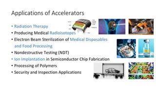
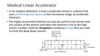
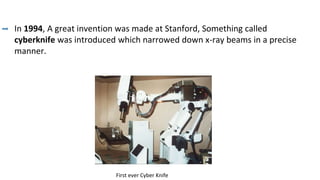
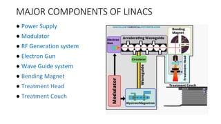
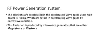
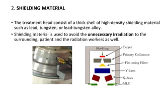
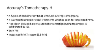
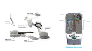
2. What is an Accelerator ??
▪ Accelerator is a device which used to speed up a beam of charged
particles to near the speed of light before they collide with a target or
with another beam of particles.
• The sub-nucleus particles created by the collision as well as the
radiation emitted are detected and analyzed. Some of these machines
accelerate particles in a straight line, and we call them linear
accelerators.
Other high-energy machines are based on rotating the
accelerated particles in a circular path, such as the cyclotrons and the
synchrotrons.
3. Applications of Accelerators
• Radiation Therapy
• Producing Medical Radioisotopes
• Electron Beam Sterilization of Medical Disposables
and Food Processing
• Nondestructive Testing (NDT)
• Ion Implantation in Semiconductor Chip Fabrication
• Processing of Polymers
• Security and Inspection Applications
4. Medical Linear Accelerator
• In its simplest definition, a linear accelerator (linac) is a device that
uses electromagnetic waves, in the microwave range, to accelerate
electrons.
• The highly accelerated electron can also be used to treat tumor near
the surface of the patient and when the electron is hit to the high
atomic number material (Tungsten) it produces X-rays that are used
to treat the deep down tumors.
5. History
In 1952, two innately talented physicists,
Namely Henry Kaplan and Ed Ginzton began
working on the concept of a linear accelerator.
In 1956, in the Stanford hospital in San Francisco,
the first linear accelerator was installed.
In 1962, a series of experiments began to see
if radiation works best with chemotherapy. Kaplan and Saul Rosenberg
worked together to improve the chances of patients' survival.
6. This patient, a 2-year-old boy
suffering from
retinoblastoma, was the first
to undergo X-ray treatment
from a medical linear
accelerator that Kaplan
developed with campus
physicists.
7. In 1994, A great invention was made at Stanford, Something called
cyberknife was introduced which narrowed down x-ray beams in a precise
manner.
First ever Cyber Knife
8. In 1997, A further step was taken to advance the use of
linear accelerators by combining with intensity modulation
radiation therapy.
The result was that many thin beams of radiation
could be achieved from any desired angle.
In 2004, four-dimensional radiotherapy was implemented.
In 2007,Volumetric Modulated Arc Therapy (VMAT) was introduced.
9. MAJOR COMPONENTS OF LINACS
● Power Supply
● Modulator
● RF Generation system
● Electron Gun
● Wave Guide system
● Bending Magnet
● Treatment Head
● Treatment Couch
10. Power Supply
• A Power supply provides Direct current (DC) power to the
modulator,which includes the pulse forming network and a switch
tube known as Hydrogen thyratron.
• High voltage pulses from the modulator section are flat-topped DC
pulses of a few microseconds in duration.
• These pulses are delivered to the magnetron and klystron
simultaneously.
11. Modulator
• This vital component of the Linear accelerator is usually located in the
treatment room In some Units.
• This modulator cabinet contains three major components,
1. Fan control (cooling the power-distribution system)
2.Auxiliary power distribution system (contains the emergency off
button that shuts off the power to the treatment unit)
3.Primary power-distribution system.
12. RF Power Generation system
• The electrons are accelerated in the accelerating wave guide using high
power RF fields. Which are set up in accelerating wave guide by
microwave radiation.
• This Radiation is produced by microwave generators that are either
Magnetrons or Klystrons
13. Magnetron
• It produces microwave required for electron
Acceleration
• Functions as a high frequency oscillator.
• Peak power up to 5MV can be produced by Magnetrons
• Typical high voltage pulse of about 50kVp is a few
microseconds long and is repeated a few hundred times
per second.
• Pulse repetition frequency (PRF) differs according to
manufacturer, PRF determins the X-ray Energy from Linac.
14. Klystron
• It is not a generator of microwaves but acts
as a RF power amplifier.
• Driven by low power microwave oscillator.
• Peak power on the order of 7MV or higher.
• Mainly using in high energy linacs.
• It uses High DC voltage.
15. Injection System
• Injection system or the source of the electrons is importantly a simple electrostatic
accelerator known as an Electron gun.
• When a high voltage is given to the cathode it gets heated up under vacuum which provides
sufficient thermal energy to the electrons to draw itself out from the material and get
ejected by thermionic emission.
• The number of electrons produced depends upon the temperature of the filament which is
controlled.
16. The electron gun and waveguide system are evacuated to a low
pressure to make the mean free path of electrons between atomic
collisions long compared to path in the system.
Electron
GUN
17. WAVEGUIDE
• The waveguide is a channel directing the microwave power of the
klystron/magnetron to the Accelerating wave guide.
• Waveguides are evacuated or gas filled (Sulfur Hexaflouride)metallic
structures.
• Two types of waveguides are used in linac :
1. Radiofrequency power transmission wave guide (usually gas filled)
2. Accelerating wave guides (usually evacuated)
• For electron transmission Accelerating waveguides are used.
19. Accelerating Waveguide
• Electrons are accelerated through the holes in the discs using an
oscillating electric field supplied by the radio-frequency generator
(magnetron or klystron) and modulator.
• Accelerating waveguides may be either of the traveling-wave or
standing-wave based on the time dependent variation of their electric
field
20. Accelerating Waveguide
Travelling Waveguide
• Waveguide length will be greater
• At the end of the waveguide microwaves
are absorbed without any reflection or fed
back to the input
• It requires low microwave peak power
• Requires lower mean RF power
Standing Waveguide
• Side coupling will reduce waveguide length
• At the end of the waveguide microwaves
are reflected back to the input
• It requires high microwave peak power
than travelling wave guide
• Requires higher mean RF power (25%
more)
21. Electron Beam Transport
• It consist of the evacuated drift tubes and bending magnets,which
are used in transporting the electron beam from the accelerating
waveguide to the X-ray target or the exit window for electron beam
therapy.
• Steering and focusing coils installed on the accelerating waveguide
are usually linked with electron transport system
Bending
magnet
Electron Gun
Electron Beam
22. Steering Coils :
• The steering coils keep the accelerated electron pencil beam as close as
possible to the axis of the cylindrical accelerating waveguide.
• It will steer the beam towards the opening which connects the accelerating
waveguide to the target.
23. Focusing Coils :
• Focusing coil is to focus the accelerated pencil beam in order to minimize the
beam divergence and cross section.
• Divergence results from a small radial component of the electric field in the
accelerating waveguide and from the repulsion among electrons in the pensil
beam.
• The focusing solenoid coils are coaxial
with the accelerating waveguide.
24. Treatment Head
➢ Bending magnet.
➢Shielding material.
➢X-ray target.
➢Primary collimator.
➢Beam flattening filter and Scattering foil.
➢Beam monitoring devices.
➢Secondary collimators.
➢MLC and Wedge.
➢Field light
25. 1. BENDING MAGNET
• Changes the direction of electron beam downward towards the isocentre.
Slalom (Achromatic) 270° bending (Chromatic)
• Bending magnet not only directs the beam to strike the target,but also
focuses the beam to diameter of 1mm.
• The design of magnets enables them to focus the electron of slightly
different energies on the same point on target (Achromatic behavior)
26. 2. SHIELDING MATERIAL
• The treatment head consist of a thick shell of high-density shielding material
such as lead, tungsten, or lead-tungsten alloy.
• Shielding material is used to avoid the unnecessary irradiation to the
surrounding, patient and the radiation workers as well.
27. 3. X-RAY TARGET
• The pencil electron beams strikes on the
X-ray target to produce photons.
• X-ray target used is transmission type target.
• It is made of Tungsten due to its high atomic
number (Z=74) and High melting point 3370°C.
28. 4. PRIMARY COLLIMATOR
• The treatment beam is first collimated by a fixed primary
collimator located immediately beyond the X-ray target.
• Conical opening projecting into a tungsten
shielding block.
• It attenuates the primary x-ray beam
intensity to less than 0.1% of the initial value
• In the case of X-rays, the collimated beam then passes
through the flattening filter.
• In the electron mode, the filter is moved out of the way.
29. 5. FLATTENING FILTER
• The photon dose distribution produced by a Linac is strongly forward peaked.
• Modifies the narrow, non-uniform photon beam at the
isocenter into a clinically useful beam through a
combination of attenuation at the center of the beam
and scatter into the periphery beam
30. • It is made up of Pb, Tungsten.
• Carroesel is a device in the treatment head which helps
in the movement of flattening filters of different energies
and Scattering foil as well.
• Moves flattening filter away from the
beam in FFF (Flattening filter free) mode either.
Structure of Flattening filter
Structure of Carroesel
31. 6.SCATTERING FOILS
• In the electron mode of linac operation , the beam instead of
striking the target , is made to strike an electron scattering foil to
spread the beam as well as get a uniform electron
fluence across the treatment field.
• It consist of a thin metallic foil, usually made of lead
32. 7. BEAM MONITORING DEVICE
• The flattened X-ray beam or the electron beam is incident on the Beam
monitoring devices.
• The dose delivered to the patient, Dose rate and field symmetry are
measured and controlled by the monitoring system.
• The chambers are usually transmission type.It consist of two flat parallel
plate type ionization chambers .
33. • Here the first chamber is the Primary dosimeter, it measure and stops the
radiation when the required dose is delivered.
• The other chamber is the backup one it stops the radiation when primary
chambers fails.
• The monitor chambers in the treatment head are usually sealed so that their
response is not influenced by temperature and pressure of the outside air.
34. 8.SECONDARY COLLIMATOR
• It consist of four blocks, two forming the upper and two forming the lower.
• Provide rectangular or square field (up to 40x40cm ) at the linac isocenter.
• This collimators are able to rotate about their axis and this degree of freedom
is referred to as collimator rotation.
• Usually made of lead or tungsten.
Set-up A with collimator Rotation Set-up B with shielding blocks
35. 9.WEDGES
• These are the beam modifying devices.
• It causes a progressive decrease in the intensity
across the beam, resulting in a tilt of the isodose
curves from their normal positions.
• Degree of tilting depends on slope of wedge.
• Wedge angles used are: 15,30,45 & 60
• Usually made of dense material such as
lead or steel.
36. • Mainly there are 3 types of wedges;
1.Physical wedges
2.Motorized wedges
3.Dynamic wedges
37. 10. MULTILEAF COLLIMATOR (MLC)
• Group of collimating leaves that can be driven automatically,
independent to each other to generate a field of any shape.
• Made up of tungsten alloy.
• The number of leaves in commercial MLC’s are steadily increasing
• Perpetual modulation of MLC plays vital role in VMAT/Rapid Arc
and IMRT by allowing complex shaped
fields can be generated in sequence.
38. • At Medanta we have,
✓Agility MLC on Elekta’s Linacs
160 Leaves
5mm width
65mm/s leaf speed
15cm maximum overtravel.
✓Binary MLC on Accuray’s Tomotherapy
64 leaves
6.25 mm width
20 msec open –close time.
39. 11.FIELD LIGHT
• It is a field localizing device, used to display the position of the radiation field
on the patient skin.
• A high accuracy bulb is placed at 45° angle with the Mercury mirror placed in
the space between the chambers and the jaw projects a light beam as if
emitting from X-ray focal spot.
• Thus the light field is congruent with
the radiation field.
40. Lasers
• The accuracy of the laser guides in determining isocenter position.
• Isocenter is a virtual point where the central axis of the Gantry,Collimator
and Couch meets.
• 2 side lasers,sagittal and ceiling lasers are mounted on walls of LINAC Unit.
• Tolerence of Laser position is 2mm.
41. Treatment Couch
• Treatment table is a mechanically movable motor driven couch.
• It can move the patient Lateral (X) ,longitudinal (Y) ,vertical (Z)
• Provides Isocentric rotation.
• Hexapod can be mounted on Treatment couch.
• Hand pendent conatins switches can be
used to access movement of table,
Gantry , Couch,Collimator jaws (field size),SSD etc..
42. Electron Applicators
• In electron-beam mode, a well defined electron
beam passing through the thin window of the
accelerator vacuum system is transported
through a scattering foil system in order to
broaden the beam.
• Electrons undergo significant scattering in the
air between the scattering foils and the patient.
• It is therefore necessary to collimate the beam with
an applicator attached to the treatment head.
43. • The electron applicator currently in use constructed of light-weight fiberglass
and aluminum.
44. Accessories and Systems used with LINAC
• Electronic Portal Imaging device (EPID)
• Cone Beam CT (CBCT) / On Board Imaging.
• HEXAPOD
• Active Breathing Co-ordinator
• Treatment and Verification system
• Treatment Planning system
45. Accessories and Systems used with LINAC
• Electronic Portal Imaging device (EPID)
• Cone Beam CT (CBCT) / On Board Imaging.
• HEXAPOD
• Active Breathing Co-ordinator
• Treatment and Verification system
• Treatment Planning system
46. Accessories and Systems used with LINAC
• Electronic Portal Imaging device (EPID)
• Cone Beam CT (CBCT) / On Board Imaging.
• HEXAPOD
• Active Breathing Co-ordinator
• Treatment and Verification system
• Treatment Planning system
47. Accessories and Systems used with LINAC
• Electronic Portal Imaging device (EPID)
• Cone Beam CT (CBCT) / On Board Imaging.
• HEXAPOD
• Active Breathing Co-ordinator
• Treatment and Verification system
• Treatment Planning system
48. Care and Usage
• The way a linear accelerator is cared for, and how often its used, can also
determine its useful life.
• Proper maintenance, like adhering to scheduled Preventative Maintenance
Inspections (PMI) , can uncover small problems before they become bigger.
• Another chief consideration is the linear accelerators usage, often measured
in beam hours or filament hours.
• Newer technologies like VMAT (volumetric arc therapy) require much more
use of “beam on” time and can reduce the lifespan of a linear accelerator
49. • The X-ray produced are almost 1 percent of the electron energy which is
striking on a target, rest of the energy (99%) is converted into heat.
This heat needs to be cooled and is achieved by Cooling system consist
of water chiller.
• Air-conditioning and humidity control in the treatment room with a certain
number of air volume replacements per hour is required for proper
functioning
50. Safety
• The facility should be prepared and equipped to deal with any
emergency situation such as unwanted Radiation exposure, Fire and
other accidents.
• To minimise hazards due to high voltage, caution sign boards with
danger signs and visual indication should be put up near such locations
• Audio visual communication between the treatment room and control
room.
52. Elekta’s Synergy and Infinity
YEAR OF INSTALLATION SYNERGY – 2009
INFINITY - 2010
ENERGY (X-RAY) 4MV, 6MV and 15 MV
ENERGY (ELECTRON) 4-22Mev
DOSE RATE (Maximum) 1400 MU/m (FFF), 600 MU/m (FF)
IMAGING XVI (CBCT) , iViewGT (EPID)
MLC 160 LEAVES (AGILITY MLC)
MLC SPEED 65mm/s
MLC THICKNESS 5mm
FIELD SIZE (max) 40cm*40cm
MICROWAVE SOURCE MAGNETRON
✓ ELEKTA SYNERGY is equipped with HEXAPOD Evo RT system
53. Accuray’s Tomotherapy-H
• A fusion of Radiotherapy Linac with Computered Tomography.
• It is armed to provide Helical treatments which is boon for large sized PTVs.
• Flat couch provided allows automatic translation during treatment, is
calliberated by IEC
• 6MV FFF
• Integrated MVCT system (3.5 MV)
54. Accuray’s Tomotherapy-H
• A fusion of Radiotherapy Linac with Computered Tomography.
• It is armed to provide Helical treatments which is boon for large sized PTVs.
• Flat couch provided allows automatic translation during treatment, is
calliberated by IEC
• 6MV FFF
• Integrated MVCT system (3.5 MV)
55. YEAR OF INSTALLATION 2015
ENERGY 6MV FFF
DOSE RATE 865 MU/minute
IMAGING C-TRUE (3.5 MV)
MLC 64 BINARY LEAVES
MLC THICKNESS 0.625 MM
MLC SPEED (OPEN TO CLOSE) 20 ms
FIELD SIZE (MAX) 5CM*40CM
GANTRY ROTATION (MAX) 6 rpm
Tomotherapy Linear Accelerator
56. Accuray’s Cyberknife VSI
• Sub-milimetre accuracy treatment anywhere in
the body, with continual image guidance.
• 6D Robotic Arm-Mounted Linac.
• Enables the delivery of a large number of
non-isocentric ,non-coplanar beams individually
directed at unique points within the intented target.
• 6MV FFF
• 1000 MU/Minute
57. Accuray’s Cyberknife VSI
• Sub-milimetre accuracy treatment anywhere in
the body, with continual image guidance.
• 6D Robotic Arm-Mounted Linac.
• Enables the delivery of a large number of
non-isocentric ,non-coplanar beams individually
directed at unique points within the intented target.
• 6MV FFF
• 1000 MU/Minute