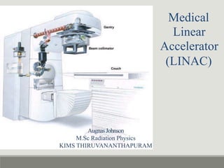
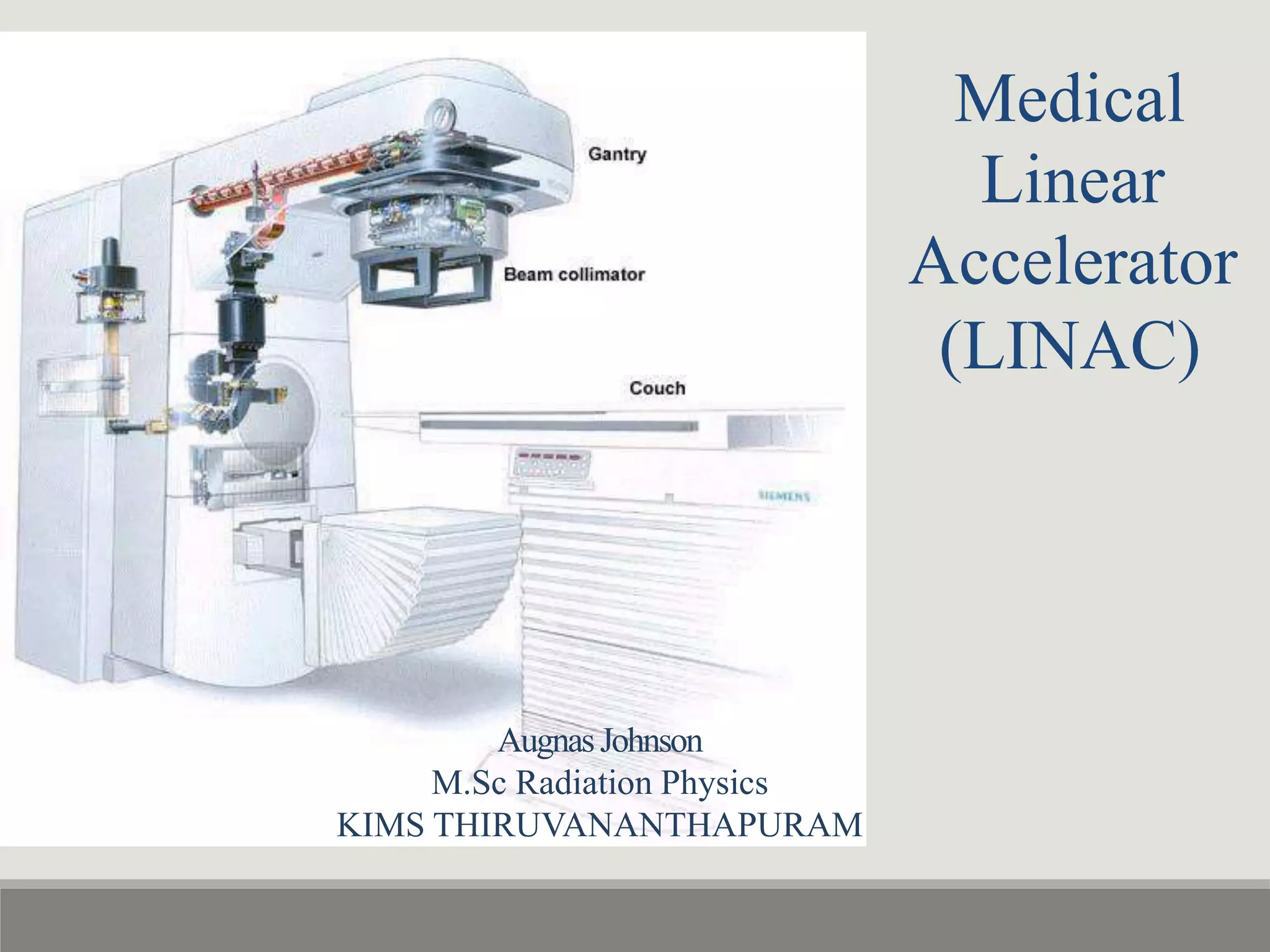
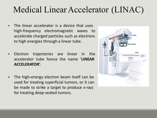
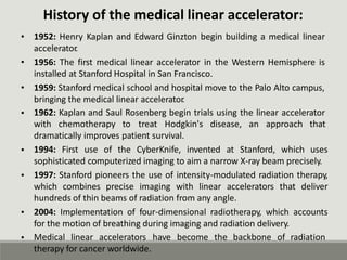
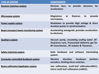
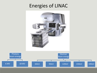
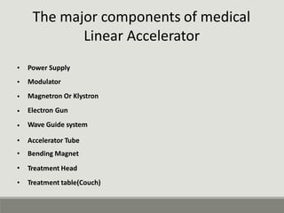
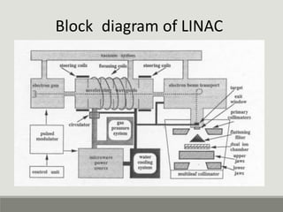
2. Medical LinearAccelerator (LINAC)
⢠The linear accelerator is a device that uses
high-frequency electromagnetic waves to
accelerate charged particles such as electrons
to high energies through a linear tube.
⢠Electron trajectories are linear in the
accelerator tube hence the name âLINEAR
ACCELERATORâ.
⢠The high-energy electron beam itself can be
used for treating superficial tumors, or it can
be made to strike a target to produce x-rays
for treating deep-seated tumors.
3. History of the medical linear accelerator:
1952: Henry Kaplan and Edward Ginzton begin building a medical linear
accelerator
.
1956: The first medical linear accelerator in the Western Hemisphere is
installed at Stanford Hospital in San Francisco.
1959: Stanford medical school and hospital move to the Palo Alto campus,
bringing the medical linear accelerator
.
1962: Kaplan and Saul Rosenberg begin trials using the linear accelerator
â˘
â˘
â˘
â˘
with chemotherapy to treat Hodgkin's disease, an approach that
dramatically improves patient survival.
1994: First use of the CyberKnife, invented at Stanford, which uses
sophisticated computerized imaging to aim a narrow X-ray beam precisely.
1997: Stanford pioneers the use of intensity-modulated radiation therapy,
which combines precise imaging with linear accelerators that deliver
hundreds of thin beams of radiation from any angle.
2004: Implementation of four-dimensional radiotherapy, which accounts
for the motion of breathing during imaging and radiation delivery.
â˘
â˘
â˘
⢠Medical linear accelerators have become the backbone of radiation
therapy for cancer worldwide.
4. History of LINAC
A 2-year-old boy suffering from a tumor in his eye, was the first to undergo
X-ray treatment from a medical linear accelerator that was developed by
Henry Kaplan, MD with campus physicists.
â˘
⢠The treatment saved
his vision intact.
the child's sight and he lived the rest of his life with
Henry Kaplan (left), and head of radiologic
first physicist
The first patient to receive radiation therapy from
the medical linear accelerator at Stanford was a 2-
year-old boy.
physics Mitchell Weissbluth, the
Kaplan hired, at the working end of the
Stanford accelerator.
5. Generationâs of Linac
â˘
â˘
â˘
â˘
The first one was installed in Hammersmith in 1952.
In 1956 ,the first patient was treated at Stanford University in USA.
The LINAC had an 8-MV Xray beam with limited gantry motion.
These LINACs were large and bulky.
6. Second generation
⢠The second generation was isocentric and could rotate 360o around the
gantry axis.
They were built between 1962-1982.
They increased the accuracy and precision of Dose delivery.
â˘
â˘
7. Third generation
⢠Better accelerator waveguides and bending magnet
beam modifying accessories.
systems and more
â˘
â˘
Wider range of energies , dose rates, field sizes and operating modes.
Higher reliability and computer driven.
8. Linear accelerator consists of :
1)
2)
3)
4)
5)
6)
7)
8)
9)
Electron injection system
Microwave system
Power supply system
Beam transport beam monitoring
Auxiliary system
Safety interlock system
system
Computer controlled feedback system
Beam collimator/applicator system
Cooling system
10) Control console system
9. TYPE OF SYSTEM COMPONENTS
Electron injection system Electron Gun, to provide electrons for
acceleration.
Microwave system Magnetron
microwaves.
or Klystron to provide
Power supply system Modulator to provide High voltage & short
duration pulses in synchronization.
Beam transport beam monitoring system Accelerating waveguide ,provides acceleration
to electrons.
Auxiliary system Vacuum pump, circulating cooling water ,RF
frequency tune, Pressurized dielectric gas for
RF transmission , RF isolator & Thyratron.
Safety interlock system Both Hardware and software interlocking
system.
Computer controlled feedback system Monitor chamber, Hardware position
encoders, limiting micro switches.
Beam collimator/applicator system Jaw collimators, multi-leaf collimators(MLC),
micro multi leaf collimators (mMLC).
11. The major components of medical
Linear Accelerator
â˘
â˘
â˘
â˘
â˘
Power Supply
Modulator
Magnetron Or Klystron
Electron Gun
Wave Guide system
â˘
â˘
â˘
â˘
Accelerator Tube
Bending Magnet
Treatment Head
Treatment table(Couch)
13. Modulator and power supply
⢠This important component of the linear
accelerator is usually located in the treatment
room In some Units.
The Modulator cabinet contains three major
components
â˘
i. Fan control (cooling the power-distribution
system).
ii. Auxiliary power distribution system
(contains the emergency off button that
shuts off the power to the treatment unit ).
Primary power-distribution system .
iii.
⢠A power supply provides direct current (DC) power to the modulator, which includes the
pulse-forming network and a switch tube known as hydrogen thyratron.
⢠High voltage pulses from the modulator section are flat-topped DC pulses of a few
microseconds in duration.
⢠These pulses are delivered to the magnetron or klystron and simultaneously to the
electron gun.
14. Magnetron
The magnetron is a device that produces microwaves.
It is a high-power oscillator, generates microwave pulses of
frequency of about ~3,000 MHz.
Magnetron is cylindrical construction consists of evacuated
central cathode and an outer anode with resonant cavities
machined out of a solid piece of copper
.
The cathode is heated by an inner filament and the electrons
are generated by thermionic emission.
Both the electron gun and the Magnetron are fed with High
â˘
â˘
â˘
â˘
â˘
voltage power supply & short duration pulses in
with the Modulated power supply system.
synchrony
⢠Typical high voltage pulse of about 50kVp is a few micro
times per
seconds long and is repeated a few hundred
second.
⢠Pulse repetition frequency (PRF) OR Pulse per second differs
according to manufacturer but pulse width remains
constant.(Pulses are of about 4Âľs duration & are delivered at
a PRF of 250Hz.)
PRF or PPS determines the dose rate from a LINAC.
â˘
15. WORKING:
⢠A static magnetic field is applied perpendicular to the plane of the cross
section of the cavities and a pulsed DC electric field is applied between the
cathode and the anode.
The electrons emitted from the cathode are accelerated toward the anode
by the action of the pulsed DC electric field. Under the simultaneous
influence of the magnetic field.
The electrons move in complex spirals toward the resonant cavities,
radiating energy in the form of microwaves. The generated microwave
pulses are led to the accelerator structure via the waveguide.
â˘
â˘
16. Klystron
The Klystron is a microwave amplifier. It
is driven by a low-power microwave
oscillator.
â˘
⢠The electrons produced by the cathode
are accelerated by a negative pulse of
voltage into buncher cavity which is
energized by low-power microwaves.
⢠The microwaves set up an alternating
electric field across the cavity.
⢠The velocity of the electrons
by the action of this electric
varying degree by a process
velocity modulation.
is altered
field to a
known as
17. Klystron
⢠Electrons form bunches due to variation in velocity resulting in bunching
of electrons as the velocity-modulated beam passes through a field-free
space in the drift tube.
As the electron bunches arrive at the catcher cavity, they induce charges
on the ends of the cavity and thereby generate a retarding electric field.
The electrons suffer deceleration, and by the principle of conservation of
energy, the kinetic energy of electrons is converted into high-power
microwaves.
â˘
â˘
18. Electron Gun
⢠It is responsible for producing electrons and injecting them into the
accelerator structure .
Tungsten Mesh/coil produces a stray of electrons due to thermionic
emission when voltage is applied in terms of âFilament currentâ.
The electron gun and the source are pulsed so that the high velocity
electrons are injected into the accelerating waveguide at the same time as
it is energized by the microwaves.
The number of electrons ejected depends upon the temperature of the
filament.
The electron gun and waveguide system are evacuated to a low pressure
â˘
â˘
â˘
â˘
to make the mean free path of electrons between atomic collisions
compared to path in the system.
long
19. Wave Guide
Accelerator Guide :
system
Also called as the accelerator structure
mounted in the gantry:
,
i) Horizontally (High-energy machines)
ii) Vertically (low-energy machines ).
⢠Microwave power (produced in the klystron) is transported to the accelerator
structure, in which corrugations(wrinkle) are used to slow the waves.
⢠Accelerating electrons tends to diverge, partly by the mutual coulomb
repulsion and mainly by the radial component of electric field in waveguide
structure.
Electrons are focused back to their path by the use of co-axial magnetic
focusing field generated by the coaxial coils which are coaxial with accelerating
waveguide.(Also called as steering coils)
â˘
20. Types of waveguide system
1) Travelling waveguide system 2)Standing wave guide system
Travelling waveguide system
⢠Travelling wave guide structure require relatively longer accelerating
waveguide.
Functionally, traveling wave structures require a terminating, or "
dummy," load to absorb the residual power at the end of the structure,
thus preventing a backward reflected wave.
â˘
21. Standing wave guide system
⢠Standing wave guide structure helps in reducing the accelerating length
due to option of side coupling cavities.
The standing wave structures provide maximum reflection of the waves
at both ends of the structure so that the combination of forward and
reverse traveling waves will give rise to stationary waves as the
microwave power is coupled into the structure via side coupling cavities.
Such a design tends to be more efficient than the traveling wave designs
since axial, beam transport cavities, and the side cavities can be
independently optimized.
â˘
â˘
22. Treatment head
Treatment head comprises of components
and monitor the treatment beam.
⢠that are designed to shape
Bending magnet:
Shielding material:
X-ray target:
Primary collimator
Beam flattening filter:
Scattering foil:
Beam monitoring devices:
Secondary collimators:
Field light:
23. Bending magnet
⢠The electrons exit the waveguide and enter the âflay tubeâ
where electron beam is redirected towards the target, the
electrons travel along a âSlalomâ path
tube.
within the flay
⢠Three pairs of magnets on the either side of the Flay tube,
cause the electron beam to bend through the turns of the
Slalom.
This process not only positions the beam to strike the
target, but also focuses the beam to a diameter of 1mm.
The design of the magnets enables them to focus the
electrons of slightly different energies on to the same
point on the target (Achromatic behavior)
â˘
â˘
24. Slalom 900 Bending (Achromatic )
Chromatic 2700 Bending
⢠In the higher-energy linacâs, however,
and, therefore, is placed horizontally
horizontal.
the accelerator
or at an angle
structure is too long
with respect to the
⢠The electrons are then bent through a suitable angle (usually about 90 or
270 degrees) between the accelerator structure and the target.
90 degree magnets (Achromatic) have the property that any energy spread
results in spatial dispersion of the beam.
270 degree magnets (chromatic) designed to eliminate spatial dispersion.
â˘
â˘
25. ⢠Shielding material :The treatment head consists of
a thick shell of high-density shielding material such
as lead, tungsten, or lead-tungsten alloy.
Shielding material is used to avoid the unnecessary
â˘
irradiation to the surroundings, patient
the radiation workers.
as well as
⢠X-ray target: The pencil electron beam
the x-ray target to produce photons.
strikes on
⢠X-ray target used is transmission type target .It
used is mainly made of Tungsten due to its high
atomic
33700C.
number(Z = 74) & High melting point
26. ⢠Primary collimator : The treatment beam is
first collimated by a fixed primary collimator
located immediately beyond the x-ray target.
In the case of x-rays, the collimated beam
then passes through the flattening filter
. In the
electron mode, the filter is moved out of the
way.
⢠Flattening filter: Modifies the narrow, non-
uniform photon beam at the isocenter into a
clinically useful beam through a combination
of attenuation of the center of the beam and
scatter into the periphery of the beam.
It is made up of lead, steel or copper
.
â˘
27. ⢠Scattering foil: In the electron mode of linac
operation, narrow pencil electron beam, about 3
mm in diameter., instead of striking the target, is
made
spread
to strike an electron
as well
scattering foil to
the beam as get a uniform
electron fluence across the treatment field.
⢠The scattering foil consists of a thin high-Z
metallic foil (e.g., lead, tantalum) .
⢠The thickness of the foil is such that most of the
electrons are scattered instead of suffering
bremsstrahlung.
Carrousel is a device in treatment head which
helps in the movement of âFlattening filters of
different energies as well as Scattering foilsâ.
â˘
28. ⢠Beam monitoring devices: The flattened x-ray
beam or the electron beam is incident on the dose
monitoring chambers.
⢠The monitoring system are transmission type ion
chambers or a single chamber with multiple plates.
cylindrical thimble chambers have also been used in
some linacâs.
⢠The function of the ion chamber is to monitor dose rate, integrated dose, and
field symmetry.
As the chambers are in a high-intensity radiation field and the beam is pulsed,
the ion collection efficiency of the chambers should remain unchanged with
changes in the dose rate.
Bias voltages in the range of 300 to 1,000 V are applied across the chamber
electrodes, depending on the chamber design.
The monitor chambers in the treatment head are usually sealed so that their
response is not influenced by temperature and pressure of the outside air
.
â˘
â˘
â˘
29. ⢠Secondary collimators: the beam is further collimated by
a continuously movable x-ray collimators.
This collimators consists of two pairs of lead of tungsten
blocks (jaws} which provide a rectangular opening (from
0X0 to 40X40 cm2) projected at a standard distance such
as 100 cm from the x-ray source.
The collimator blocks are constrained to move so that the
block edge is always along a radial line passing through
the x-ray source position.
â˘
â˘
⢠Field light: The field size definition is provided by a light
localizing system in the treatment head.
A combination of mirror and a light source located in the
space between the chambers and the jaws projects a light
beam as if emitting from the x-ray focal spot.
Thus the light field is congruent with the radiation field.
â˘
â˘
allows accurate positioning of the radiation field in
relationship to skim marks or other reference points.
30. f
d
Field Light and lasers
â˘
â˘
Field Light :
It is a Field localizing device, Used to display the
position of the radiation field on the patient skin.
An high accuracy bulb is placed at 450 angle with the
â˘
Mercury mirror placed in the path of the beam
(Transmission type mirror) .
⢠The light field size
field size.Field size
âLight field size)
is in congruence with the radiation
can be varied with the help of this
â˘
â˘
Lasers:
The accuracy of the laser guides in determining
Isocenter position.
Isocenter is a virtual point where the central axis
o
Gantry, Collimator and couch meets.
2 Side lasers, saggital and Ceiling lasers are
mounte on walls of LINAC unit.
Tolerance of laser position is 2 mm
â˘
â˘
â˘
31. Treatment table(Couch)
⢠Treatment table (Couch) : Treatment table is a
mechanically movable motor driven couch .
Patient is positioned over the treatment table according
to the desired co-ordinates of planning.
Patient is immobilized using the Immobilization devices.
Treatment table can be moved Horizontal, Vertical as well
as Rotational directions.
â˘
â˘
â˘
⢠Hand Pendent: It contains all the control switches which
can be used to access the movement of Gantry, Couch,
Collimator jaws(Field size),SSD etc.,
32. Cooling system
⢠Heat dissipation in linear accelerator is an important step in maintenance
in large setup and heavy patient load in hospitals.
The x-rays produced are almost the 1 percent of the electron energy which
is striking on the target.
Hence 99% of the energy is converted to heat.
This heat is needed to be cooled and that is achieved by the âCooling
systemâ.
Cooling system consists of âwater chillerâ for cooling the water and water
inlets and outlets to various parts of LINAC including X-ray target.
â˘
â˘
â˘
â˘
33. Radiation Safety/interlock system
⢠Similar to treatment from radiation the Safety from radiation also plays an
important role in Radiotherapy.
Various Interlocks are present in LINAC to avoid the mis-happens or wrong
treatment to the patient.
Interlocks indicates the problem in particular device in the LINAC assembly
and interlocking system helps in solving the particularly and easily.
Safety Interlocks include:
â˘
â˘
â˘
1)
2)
3)
Last Man Out Switch(LMO)
Door interlock
Beam ON/OFF Key etc.,
⢠Emergency switches are provided at all the systems of an LINAC unit to
completely turn Off the entire Unit with only single switch during
emergency situations.
34. Working: Photon Beam Therapy
Photons of energies 6MV & 18MV can be produced for treatment in
Medical linear accelerator.
Modulator produces the necessary potential for the whole accelerator
mainly the Magnetron/Klystron and the electron gun.
Electrons are produced by the electron gun and proceeded to the wave
guide system.
An 3mm electron âpencil beamâ is produced due to acceleration and the
focusing coilâs fixed all around the waveguide.
Focused beam is bent by the bending magnets and also the beam is
further focused due to reflective force of the bending magnets.
The electron beam is made to strike on the X-ray producing target.
â˘
â˘
â˘
â˘
â˘
â˘
⢠X-rays/Photon energy produced is not uniform in flatness & is
asymmetrical in nature, which is made uniform by the flattening filter.
⢠The uniform flattened beam is then passes by the monitoring chambers
and the dose rate as well as the symmetry is verified.
The beam is then ready to treat the tumor/Patient.
â˘
35. Working: Electron Beam Therapy
Electron of energies 6MeV, 9MeV, 12MeV, 15MeV, 18MeV & 20MeV can
â˘
be produced for treatment in Medical linear accelerator.
Modulator produces the necessary potential for the whole accelerator
mainly the Magnetron/Klystron and the electron gun.
Electrons are produced by the electron gun and proceeded to the wave
guide system.
An 3mm electron âpencil beamâ is produced due to acceleration and the
focusing coilâs fixed all around the waveguide.
Focused beam is bent by the bending magnets and also the beam is
further focused due to reflective force of the bending magnets.
The electron beam is made to strike on the Scattering foil to make the
electrons to distribute in forward direction.
Electron beam produced is uniform in flatness & is asymmetrical in nature,
which can be directly used for treatment.
The uniform flattened beam is then passes by the monitoring chambers
and the dose rate as well as the symmetry is verified.
The beam is then ready to treat the tumor/Patient.
â˘
â˘
â˘
â˘
â˘
â˘
â˘
37. Wedges
⢠Physical wedges are graduated pieces of lead that
have a thick end and a thin end.
The thin end causes less attenuation than the thick
end; this causes a shift in the isodose curves within
the treated volume.
The wedge is denoted by the angle it tilts the
isodose curves
eg. a 30o wedge would cause a 30o tilt in the isodose
curves.
Physical wedges are not in common use due to the
ability of the independent jaws to perform dynamic
wedging.
â˘
â˘
â˘
â˘
38. Custom Blocks
Significant irradiation of the normal tissue outside this
volume must be avoided as much as possible.
These restrictions can give rise to complex field shapes,
which require intricate blocking.
Custom blocking system uses a low melting point alloy,
Lipowit metal ( Cerrobend) , which has a density of 9.4
g/cm3 at 20°C (83% of the lead density)
This material consists of,
1) 50.0% bismuth
2) 26.7 % lead,
3) 13.3 % tin, and
4) 10% cadmium
â˘
â˘
â˘
â˘
⢠The main advantage of Cerrobend over lead is that it
melts at about 70°C and can be easily cast into any
shape.
At room temperature, it is harder than lead.
â˘
39. Multi Leaf Collimator
⢠A multileaf collimator (MLC) for photon beams consists of a
large number of collimating blocks or leaves that can be
driven automatically, independent of each other, to
generate a field of any shape.
Typically the MLC systems consists 60 to 80 pairs, which are
independently driven.
The individual leaf has a width of 1 cm or less as projected
at the isocenter
.
â˘
â˘
⢠The leaves are made of tungsten alloy (p=17.0 to
18.5g/cm3 ) and have thickness along the beam direction
ranging from 6cm to 7.5cm, depending on the type of
accelerator
.
The leaf thickness is sufficient to provide primary x-ray
transmission through the leaves of less than 2%.
The primary beam transmission may be further minimized
by combining jaws with the MLC in shielding areas outside
the MLC field opening.
â˘
â˘
40. Electronic Portal Imaging (EPID)
⢠Electronic
making
portal imaging overcomes two problems by
it possible to view the portal images
instantaneously
1) real time images can be displayed on computer screen
before initiating a treatment.
2) Portal images can also be stored on computer for later
viewing or archiving.
EPIDs use flat panel arrays of solid state detectors based on
amorphous silicon (a-Si) technology .Flat panel arrays are
compact, & easier to mount on a retractable arm for
positioning in or out of the field.
â˘
⢠A scintillator converts the radiation beam into visible
photons. The light is detected by an array of photodiodes
implanted on an amorphous silicon panel.
41. On Board Imaging (OBI)
⢠CT scans acquired with detectors imbedded in a flat panel
instead of a circular ring is known as Onboard Imaging .
CT scanning that uses this type of geometry is known as cone-
beam computed tomography (CB CT) .
In cone-beam CT
, planar projection images are obtained from
multiple directions a s the source with the opposing detector
panel rotates around the patient through 1800 degrees or more.
These multidirectional images provide sufficient information to
reconstruct patient anatomy in 3D , including cross-sectional,
sagittal, and coronal planes.
A filtered back-projection algorithm is used to reconstruct the
volumetric images.
They are mounted on the accelerator gantry and can be used to
â˘
â˘
â˘
â˘
â˘
acquire volumetric image data under actual treatment
conditions.
They enable the
⢠localization of planned target volume and
critical structures before each treatment.
The system can be implemented either by using a kilovoltage x-
ray source or the mega voltage therapeutic source.
â˘
42. ⢠Kilovoltage CBCT:
⢠Kilovoltage x-rays for a kilovoltage CBCT ( kVCBCT) system are generated by
a conventional x-ray tube that is mounted on a retractable arm at 900 to
the therapy beam direction.
A flat panel of x-ray detectors is mounted opposite the x-ray tube.
This imaging system is versatile and is capable of cone-beam CT as well 2-D
radiography and fluoroscopy.
Advantages:
Produce volumetric CT images with good contrast an sub millimeter
spatial resolution.
acquire images in therapy room coordinates, and
Use 2-D radiographic and fluoroscopic modes to verify portal accuracy,
management of patient motion, and making positional and dosimetric
adjustments before and during treatment.
â˘
â˘
â˘
1.
2.
3.
43. ⢠Megavoltage CBCT
⢠MVCBCT uses the megavoltage x-ray beam of the linear
accelerator and its EPID mounted opposite the source.
EPIDs with the a-Si flat panel detectors are sensitive enough to allow rapid
acquisition of multiple, low-dose images as the gantry is rotated through
1800 or more.
Multidirectional 2-D images, volumetric CT images are reconstructed from
these.
MVCBCT system has good image quality for the bony anatomy and, in even
for soft tissue targets.
MVCBCT is a great tool for;
On-line or pretreatment verification of patient positioning,
Anatomic matching of planning CT
,
Pretreatment CT, avoidance of critical structures such as spinal cord, and
identification of implanted metal markers if used for patient setup.
â˘
â˘
â˘
â˘
a)
b)
c)
d)
44. ⢠Advantages of MVCBCT over kVCBCT:
a) 1 Less susceptibility to artifacts due to high-Z objects such as metallic
markers in the target, metallic hip implants, and dental fillings
b) 2. No need for extrapolating attenuation coefficients from kV to
megavoltage photon energies for dosimetric corrections
⢠From images we can say that MV-CBCT image of 2.5cGy is sufficient
anatomy verification during patient positioning.
for Bony