Download to read offline
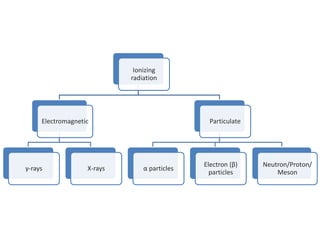
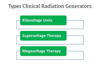

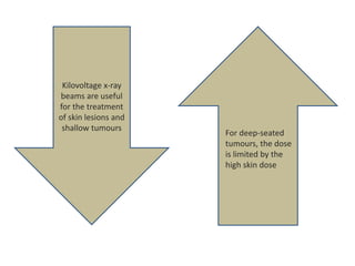
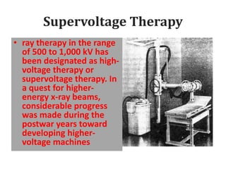
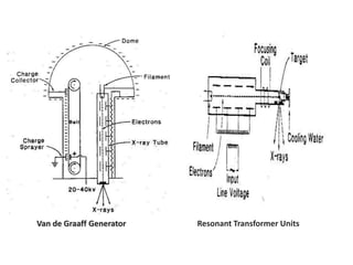

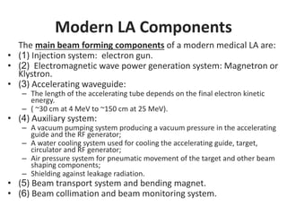
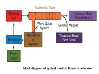
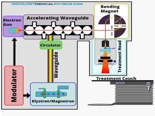
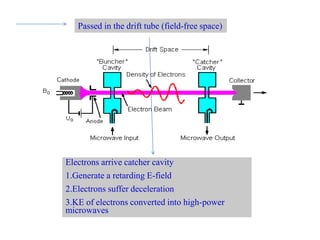
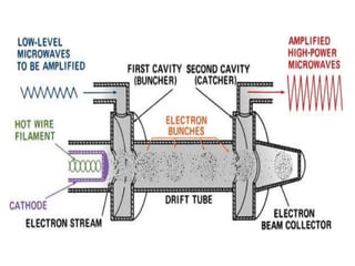
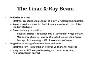
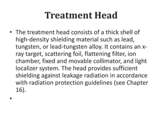
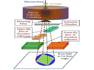
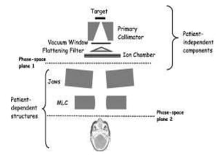

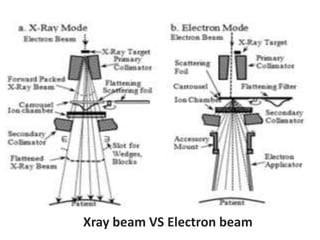


This document discusses different types of radiation used in radiation oncology. It describes the evolution from kilovoltage x-ray units to modern megavoltage linear accelerators. Key developments include the use of higher voltage x-rays called supervoltage therapy, and later the advent of megavoltage x-rays and electrons generated by linear accelerators. The document outlines the main components of linear accelerators including the electron gun, RF power source like klystrons or magnetrons, accelerating structure, and treatment head for beam shaping and monitoring.


![CASE_PRESENTATION_ON_subdural_hematoma(SDH)[1 FINAL PPT]-1.pptx](https://cdn.slidesharecdn.com/ss_thumbnails/casepresentationonsubduralhematomasdh1finalppt-1-260129172522-d405d375-thumbnail.jpg?width=640&height=640&fit=bounds)


