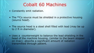
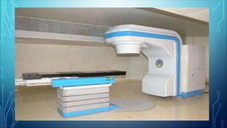
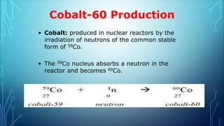
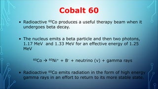
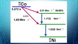
RADIOTHERAPHY
.
COBALT-60 MACHINES
• Introduced in the 1950’s, being replaced by linacs.
• The first practical radiation therapy treatment unit to
provide a significant dose below the skin surface and
simultaneously spare the skin the harsh effects of earlier
methods.
• Still used in developing countries: simpler design, cost,
little tech support.
Cobalt 60 Machines
• Constantly emit radiation.
• The 60Co source must be shielded in a protective housing
(source head).
• The source head is a steel shell filled with lead (may be up
to 2 ft in diameter).
• Uses a counterweight to balance the lead shielding in the
head of the machine housing, (similar to the beam stopper
on linac): absorbs a significant amount of radiation
transmitted through patient.
Cobalt-60 Production
• Cobalt: produced in nuclear reactors by the
irradiation of neutrons of the common stable
form of 59Co.
• The 59Co nucleus absorbs a neutron in the
reactor and becomes 60Co.
Cobalt 60
• Radioactive 60Co produces a useful therapy beam when it
undergoes beta decay.
• The nucleus emits a beta particle and then two photons,
1.17 MeV and 1.33 MeV for an effective energy of 1.25
MeV
60Co  60Ni+ + B- + neutrino (v) + gamma rays
• Radioactive 60Co emits radiation in the form of high energy
gamma rays in an effort to return to its more stable state.
60Co Source
• The overall diameter of a 60Co source is 1 to 3 centimeters.
• Consists of pellets of radioactive 60Co encased in multiple
layers of welded metal to prevent contamination of the
environment and to absorb β- particles produced by the decay
process.
• Or 60Co sources are made with the 60Co fused into a solid
cylinder. Advantages:
– Smaller source with less penumbra for the same beam
intensity
– Less hazard of contamination should a source ever become
exposed to the environment.
•The 60Co source, usually in the form of a solid cylinder,
discs, or pallets, is contained inside a stainless steel
capsule and sealed by welding. This capsule is placed
into another steel capsule, which is again sealed by
welding. The double-welded seal is necessary to
prevent any leakage of the radioactive material
60Co Activity
• 60Co activity may be expressed in curies (Ci), the historical
unit of radioactivity
– 3.7 x 10¹⁰ Becquerel (Bq)
– 1 Bq = 1 disintegration per second
• May also be defined in rhm units (roentgens per hour at 1
meter)
• Most sources have an activity of 750-9000 Ci, typically 3000-
9000 Ci used in radiation therapy
Half-life
• Half-life: the time necessary for a radioactive material to
decay to half or 50% of its original intensity.
– Requires a correction factor for this decay of about 1% per
month in all treatment calculations.
– Source must be replaced at about five year intervals.
• The half-life of 60Co is 5.26 years.
SOURCE HOUSING:
• The housing for the source is called the sourcehead.
• It consists of a steel shell filled with lead for shielding purposes and
a device for bringing the source in front of an opening in the head
from which the useful beam emerges.
• Also, a heavy metal alloy sleeve is provided to form an additional
primary shield when the source is in the off position.
• A number of methods have been developed for moving the source
from the off position to the on position.
IT WILL SUFFICE HERE TO MENTION BRIEFLY FOUR
DIFFERENT MECHANISMS:
• A) The source mounted on a rotating wheel inside the sourcehead to carry the source
from the off position to the on position.
• B) The source mounted on a heavy metal drawer plus its ability to slide horizontally
through a hole running through the sourcehead—in the on position the source faces the
aperture for the treatment beam and in the off position the source moves to its shielded
location and a light source mounted on the same drawer occupies the on position of the
source;
• C) Mercury is allowed to flow into the space immediately below the source to shut off the
beam. and
• D) The source is fixed in front of the aperture and the beam can be turned on and off by
a shutter consisting of heavy metal jaws.
All of the above mechanisms incorporate a safety feature in which the source is returned
automatically to the off position in case of a power failure.
60Co Shielding
• Cerrobend (Lipowitz metal): lower melting point than Pb,
cheaper
– 50% Bismuth
– 26.7% Lead
– 13.3% tin
– 10% Cadmium (a toxic metal can get into bloodstream)
• Density ratio of Cerrobend to Lead: 1.2 cm Cerrobend to 1 cm
lead.
– 5 HVL is needed to reduce intensity
– A thickness of 7.2 cm of Cerrobend needed, 6 cm lead.
Penumbra
• Penumbra: the area at the edge of the radiation beam at which
the dose rate changes rapidly as a function of distance from the
beam axis.
• Describes the edge of the field having full radiation intensity for
the beam compared with the area at which the intensity falls to 0.
• The larger the source size, the larger the penumbra
P = S(SSD-SDD)/SDD
• When depth is given:
P = S(SSD + D -SDD)/SDD
• Larger field sizes are necessary to cover the same amount of
tissue adequately compared to the linac.
Diagram for calculating
geometric penumbra. SDD,
source to diaphragm distance;
SSD, source to surface
distance.
Penumbra
• Geometric penumbra: the place where a lack of sharpness or
fuzzy area occurs at the edge of the beam
– Occurs at the skin surface and greater depths in tissue.
• Transmission penumbra: occurs as the radiation passes
through the edge of the primary collimators
– Occurs at the edge of the patients shielding blocks mounted
or placed below the collimator
– Correlates with the size of the collimator opening- larger field
sizes have more transmission penumbra
– Penumbra width depends upon:
– Source diameter
– SSD
– Depth below the skin and SDD(Inversely)
Reducing Penumbra
• The transmission penumbra can be reduced by using satellite
collimators, penumbra trimmers or trimmer bars.
• Trimmers are metal bars that attenuate the edge of the beam
providing a sharper field edge.
– Should be placed no closer than 15 cm from the patients
skin to reduced electron contamination (increased skin dose)
by metal devices.
• Provides enough distance for the secondary electrons
produced by the trimmer bars to lose sufficient energy
Dose Maximum:
• Dose maximum (Dmax): when a greater percentage of
dose occurs below the skin surface
• Dmax is the depth of maximum buildup, in which 100%
of the dose is deposited.
• For 60Co, Dmax occurs at 0.5 cm below the skin surface.
• Electron equilibrium is another term used to describe
Dmax. As energy increases, so does the depth of electron
equilibrium.
Beam On/Beam Off
• Turning the beam on requires physically exposing the source
either by moving it into position or by removing shields
around the source.
• Air pressure: the compressor generates air pressure by
pushing the source horizontally into position over the
collimator opening.
• Rotating wheel: the motor rotates a wheel 180 degrees by
placing the source over the collimator opening.
Warning Lights
• Red light: Radiation present- do not enter room
• Green Light: time elapsed
• Malfunction: both red and green lights still on-
means that machine is still in on position after
prescribed dose has been delivered. Remove
patient.
Timer Error
• Timer error (TE, or travel time correction, shutter error): is
a consequence of the physical motion of the source. Even if
its less than 1 second.
• The difference between the beam on time setting and the
time that the source is in the treatment position, the time it
takes to advance and retract the source
• Timer error is determined at the time of machine beam
calibration and is checked monthly.
TE = (R1t1-R2t2)/R1-R2
• The timer setting necessary for a treatment is the time
calculated plus the timer error.
Quality Assurance
• Required be the Nuclear Regulatory Commission (NRC)
• A qualified radiation/medical physicist must perform full
calibration testing annually. More frequent if:
– The source is replaced
– A 5% deviation is noticed during a spot check
– A major repair requiring the removal or restoration of major
components is done.
Quality Assurance
• Written directive: the prescription, must be clear, unambiguous,
and signed by a licensed authorized user.
• Recordable event must be reported to the RSC-Radiation Safety
Committee:
– A delivered dose more than 15% in excess of the weekly
prescription
– Lack of daily recording of dose
• Misadministration must be reported immediately to the NRC
– Treatment of the wrong patient, wrong site
– Weekly dose more than 30% in excess of the prescription
– The delivery of more than 20% (25%???) total dose
Tests
• The integrity of the source must be tested twice a year to
ensure the sealed source continues to be totally sealed.
– Wipe tests: wipe collimator edges with a filter paper,
background radiation reading done, activity is
determined (acceptable under 0.005 mCi)
• Radiation and light field coincidence
• Timer accuracy
• Dose rates
• & more.
Leakage Limits
• Leakage in the off position:
– Cannot exceed 2 mrem/hr at 1 meter
• Leakage in the on position:
– Cannot exceed 0.1% of the useful beam at 1 meter from
the source.
co 60.ppt

co 60.ppt

  • 1.
  • 2.
    COBALT-60 MACHINES • Introducedin the 1950’s, being replaced by linacs. • The first practical radiation therapy treatment unit to provide a significant dose below the skin surface and simultaneously spare the skin the harsh effects of earlier methods. • Still used in developing countries: simpler design, cost, little tech support.
  • 3.
    Cobalt 60 Machines •Constantly emit radiation. • The 60Co source must be shielded in a protective housing (source head). • The source head is a steel shell filled with lead (may be up to 2 ft in diameter). • Uses a counterweight to balance the lead shielding in the head of the machine housing, (similar to the beam stopper on linac): absorbs a significant amount of radiation transmitted through patient.
  • 5.
    Cobalt-60 Production • Cobalt:produced in nuclear reactors by the irradiation of neutrons of the common stable form of 59Co. • The 59Co nucleus absorbs a neutron in the reactor and becomes 60Co.
  • 6.
    Cobalt 60 • Radioactive60Co produces a useful therapy beam when it undergoes beta decay. • The nucleus emits a beta particle and then two photons, 1.17 MeV and 1.33 MeV for an effective energy of 1.25 MeV 60Co  60Ni+ + B- + neutrino (v) + gamma rays • Radioactive 60Co emits radiation in the form of high energy gamma rays in an effort to return to its more stable state.
  • 8.
    60Co Source • Theoverall diameter of a 60Co source is 1 to 3 centimeters. • Consists of pellets of radioactive 60Co encased in multiple layers of welded metal to prevent contamination of the environment and to absorb β- particles produced by the decay process. • Or 60Co sources are made with the 60Co fused into a solid cylinder. Advantages: – Smaller source with less penumbra for the same beam intensity – Less hazard of contamination should a source ever become exposed to the environment.
  • 9.
    •The 60Co source,usually in the form of a solid cylinder, discs, or pallets, is contained inside a stainless steel capsule and sealed by welding. This capsule is placed into another steel capsule, which is again sealed by welding. The double-welded seal is necessary to prevent any leakage of the radioactive material
  • 11.
    60Co Activity • 60Coactivity may be expressed in curies (Ci), the historical unit of radioactivity – 3.7 x 10¹⁰ Becquerel (Bq) – 1 Bq = 1 disintegration per second • May also be defined in rhm units (roentgens per hour at 1 meter) • Most sources have an activity of 750-9000 Ci, typically 3000- 9000 Ci used in radiation therapy
  • 12.
    Half-life • Half-life: thetime necessary for a radioactive material to decay to half or 50% of its original intensity. – Requires a correction factor for this decay of about 1% per month in all treatment calculations. – Source must be replaced at about five year intervals. • The half-life of 60Co is 5.26 years.
  • 13.
    SOURCE HOUSING: • Thehousing for the source is called the sourcehead. • It consists of a steel shell filled with lead for shielding purposes and a device for bringing the source in front of an opening in the head from which the useful beam emerges. • Also, a heavy metal alloy sleeve is provided to form an additional primary shield when the source is in the off position. • A number of methods have been developed for moving the source from the off position to the on position.
  • 14.
    IT WILL SUFFICEHERE TO MENTION BRIEFLY FOUR DIFFERENT MECHANISMS: • A) The source mounted on a rotating wheel inside the sourcehead to carry the source from the off position to the on position. • B) The source mounted on a heavy metal drawer plus its ability to slide horizontally through a hole running through the sourcehead—in the on position the source faces the aperture for the treatment beam and in the off position the source moves to its shielded location and a light source mounted on the same drawer occupies the on position of the source; • C) Mercury is allowed to flow into the space immediately below the source to shut off the beam. and • D) The source is fixed in front of the aperture and the beam can be turned on and off by a shutter consisting of heavy metal jaws. All of the above mechanisms incorporate a safety feature in which the source is returned automatically to the off position in case of a power failure.
  • 16.
    60Co Shielding • Cerrobend(Lipowitz metal): lower melting point than Pb, cheaper – 50% Bismuth – 26.7% Lead – 13.3% tin – 10% Cadmium (a toxic metal can get into bloodstream) • Density ratio of Cerrobend to Lead: 1.2 cm Cerrobend to 1 cm lead. – 5 HVL is needed to reduce intensity – A thickness of 7.2 cm of Cerrobend needed, 6 cm lead.
  • 17.
    Penumbra • Penumbra: thearea at the edge of the radiation beam at which the dose rate changes rapidly as a function of distance from the beam axis. • Describes the edge of the field having full radiation intensity for the beam compared with the area at which the intensity falls to 0. • The larger the source size, the larger the penumbra P = S(SSD-SDD)/SDD • When depth is given: P = S(SSD + D -SDD)/SDD • Larger field sizes are necessary to cover the same amount of tissue adequately compared to the linac.
  • 18.
    Diagram for calculating geometricpenumbra. SDD, source to diaphragm distance; SSD, source to surface distance.
  • 19.
    Penumbra • Geometric penumbra:the place where a lack of sharpness or fuzzy area occurs at the edge of the beam – Occurs at the skin surface and greater depths in tissue. • Transmission penumbra: occurs as the radiation passes through the edge of the primary collimators – Occurs at the edge of the patients shielding blocks mounted or placed below the collimator – Correlates with the size of the collimator opening- larger field sizes have more transmission penumbra – Penumbra width depends upon: – Source diameter – SSD – Depth below the skin and SDD(Inversely)
  • 20.
    Reducing Penumbra • Thetransmission penumbra can be reduced by using satellite collimators, penumbra trimmers or trimmer bars. • Trimmers are metal bars that attenuate the edge of the beam providing a sharper field edge. – Should be placed no closer than 15 cm from the patients skin to reduced electron contamination (increased skin dose) by metal devices. • Provides enough distance for the secondary electrons produced by the trimmer bars to lose sufficient energy
  • 21.
    Dose Maximum: • Dosemaximum (Dmax): when a greater percentage of dose occurs below the skin surface • Dmax is the depth of maximum buildup, in which 100% of the dose is deposited. • For 60Co, Dmax occurs at 0.5 cm below the skin surface. • Electron equilibrium is another term used to describe Dmax. As energy increases, so does the depth of electron equilibrium.
  • 22.
    Beam On/Beam Off •Turning the beam on requires physically exposing the source either by moving it into position or by removing shields around the source. • Air pressure: the compressor generates air pressure by pushing the source horizontally into position over the collimator opening. • Rotating wheel: the motor rotates a wheel 180 degrees by placing the source over the collimator opening.
  • 23.
    Warning Lights • Redlight: Radiation present- do not enter room • Green Light: time elapsed • Malfunction: both red and green lights still on- means that machine is still in on position after prescribed dose has been delivered. Remove patient.
  • 24.
    Timer Error • Timererror (TE, or travel time correction, shutter error): is a consequence of the physical motion of the source. Even if its less than 1 second. • The difference between the beam on time setting and the time that the source is in the treatment position, the time it takes to advance and retract the source • Timer error is determined at the time of machine beam calibration and is checked monthly. TE = (R1t1-R2t2)/R1-R2 • The timer setting necessary for a treatment is the time calculated plus the timer error.
  • 25.
    Quality Assurance • Requiredbe the Nuclear Regulatory Commission (NRC) • A qualified radiation/medical physicist must perform full calibration testing annually. More frequent if: – The source is replaced – A 5% deviation is noticed during a spot check – A major repair requiring the removal or restoration of major components is done.
  • 26.
    Quality Assurance • Writtendirective: the prescription, must be clear, unambiguous, and signed by a licensed authorized user. • Recordable event must be reported to the RSC-Radiation Safety Committee: – A delivered dose more than 15% in excess of the weekly prescription – Lack of daily recording of dose • Misadministration must be reported immediately to the NRC – Treatment of the wrong patient, wrong site – Weekly dose more than 30% in excess of the prescription – The delivery of more than 20% (25%???) total dose
  • 27.
    Tests • The integrityof the source must be tested twice a year to ensure the sealed source continues to be totally sealed. – Wipe tests: wipe collimator edges with a filter paper, background radiation reading done, activity is determined (acceptable under 0.005 mCi) • Radiation and light field coincidence • Timer accuracy • Dose rates • & more.
  • 28.
    Leakage Limits • Leakagein the off position: – Cannot exceed 2 mrem/hr at 1 meter • Leakage in the on position: – Cannot exceed 0.1% of the useful beam at 1 meter from the source.