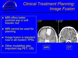
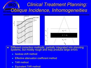
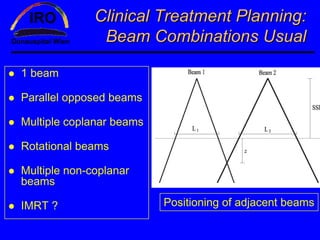
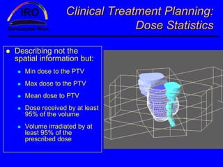
Planning systems in
   Radiotherapy
     WFO Schmidt
 Institute for Radio-Oncology
      Donauspital Vienna
Contents

Who is Mr. Schmidt ?

Handbook for Teachers and Students, IAEA, May
2003
   Chapter 7: Clinical Treatment Planning in External Beam
   Radiotherapy
   Chapter 11: Computerized Treatment Planning Systems for
   External Beam Radiotherapy

AAPM Rep 85 (2004): Tissue inhomogeneity
corrections for megavoltage Photon Beams

Remark: this is a selection of some topics – not a
total view of all aspects dealing with planning !
Personal data

Dosimetry & Radioprotection at Inst
Nucl Phys, Univ. Vienna 1977-1984

Medical Physics in Radiotherapy at
the Univ. Vienna 1984 - 1995

Medical Physics in Radiotherapy at
the Donauspital Vienna since 1995
  PACS since 1993 in Diagnostics

Stepping now into image fusion and
image-guided radiotherapy (IGRT)
My relation to
                   planning systems (TPSs):
     I do not develop planning systems but I´m an advanced and
     interested user. Main interest is to get new (and good) system
     into routine.

     systems working in our institute at present:


                 CORVUS 6.1                               PROWESS
                  HELAX 6.2                                Vs. 3.2
XiO (CMS)                                PLATO
  Vs 4.2                                 Vs14.2
What I will not talk about:
             specialized systems for:
Brachytherapy             Stereotactic radiosurgery
                          with linac or GammaKnife
Orthovoltage therapy
                          Tomotherapy
IMRT
                          Intraoperative therapy
Dynamic MLC               D-shaped beams
Total Body Irradiations   Electron beam arc
                          therapy
MicroMLC
                          Total Skin Electron
                          Irradiations
Development of TPSs
                            „historical“ dates:
~1980 :1D-planning (by hand)        ~ 2000: 4D: taking also
                                    patient movement into
~1980 – 1990: 2D-planning           account
with computers, CT starts
                                    „Parallel“ developments:
From ~1990: 2.5D-systems
                                    Inverse planning
   Eg missing knowledge how to
   handle scatter
                                    MonteCarlo-methods
   New algorithms (pencil-beam,
   convolution/superposition,...)

~1995: Real 3D available,
getting exact
Clinical Treatment Planning:
                      Definition of Volumes

Definitions of GTV, CTV,
ITV, PTV, OAR,... not
discussed here

Dose specifications:
  Min/max dose
  Mean dose
  ICRU-point

   not discussed here but
play an important role
when comparing planning
from different systems !
Clinical Treatment Planning:
              Patient data for 2D-planning

Single patient contour,
eventually with lead wire
markers, is transferred to
a sheet of paper

Simulation radiographs
are taken for each field

OARs identified and their
position identified on
radiographs

Irregular field calculation
                              Clarkson algorithm
Clinical Treatment Planning:
                 Patient data for 3D-planning
CT-data (5-10mm for thorax,
5mm pelvis, 3mm H&N)

External contour on each slice

Volumes drawn by oncologist

OARs fully outlined !!! (DVHs)

Other imaging information
(fusion)

Knowledge of inhomogeneities

Comparison of radiographs with
DRRs
Clinical Treatment Planning:
                       Treatment simulation

Determination of patient
treatment position

Identification of TVs & OARs

Determination and
verification of field geometries

Generation of radiographs for
comparison with portfilms/PI

Acquisition of patient data for
further planning
Clinical Treatment Planning:
     Patient positioning, immobilization

Immobilization devices
have 2 fundamental roles:
  Immobilising patient
  Reproducing patient position
  from CT/simulator and
  between fractions

Usually for Head and H&N

Additional devices (eg
vacuum-based) needed for
special treatments
Clinical Treatment Planning:
           Localization, Beam Geometries

Localisation of (mostly
invisible) PTVs and OARs

Setting up and positioning
the patient
   Taking geometrical data (FSD,
   angles, fieldsizes,...
   Taking radiographs
   Taking pictures (digitally)

Taking data for irregular
fields (eg with lead wires)
Clinical Treatment Planning:
              CT-Patient Data - Advantages
Excellent soft tissue contrast

Easy contouring

Electron density    planning

TVs and OARs can easily be
identified

Scout views

Position of TVs relative to
bony anatomy

   fields conform TVs much
better
Clinical Treatment Planning:
                            Virtual Simulation
Prior to scanning marking of a
reference isocenter

TVs and OARs are outlined
directly at the CT

Use of standard beam geometries
or unorthodox techniques

Defining the ICRU-point in the
PTV

Patient first is adjusted to the
reference isocenter (stable
markers), then the ICRU-point is
set into the isocenter by moving
the table to calculated coordinates   Large opening necessary
                                            Best >80cm
Clinical Treatment Planning:
               Virtual Simulation - DRRs

Digitally reconstructed
radiographs from CT-
dataset

Mandatory for
comparing patient
images with portfilms or
portal images

Oftehn combined with
Beam´s Eye Views
(BEVs)
Clinical Treatment Planning:
                  Virtual Simulation - BEVs

BEVs are projections of the
treatment beam axes onto
(mostly) a DRR

DRRs ideally should be
transferred through image
networks – but they contain
colors !
  Definition of new standard for
  radiotherapy – DICOM RT !
Clinical Treatment Planning:
    Conventional vs. Virtual Simulation
Better soft tissue contrast in
CT

DRRs and BEVs in CT

Setting anatomical landmarks

Patient has only to be present
at the CT – much shorter !

Do you still need a
conventional simulator if you
have your own CT ?
   Radiographs from treatment
   setup are fine !
Clinical Treatment Planning:
                              Image Fusion

MRI offers better
contrast esp in soft
tissues, but

MRI cannot be used for
planning

Image fusion is standard
now in all modern TPSs

Other modalities also
important (eg PET, US)     MRI        CT
Clinical Treatment Planning:
      Simulation - Summary
Clinical Treatment Planning:
Simulation – Summary (cont.)
Clinical Treatment Planning:
                   Treatment Aids - Wedges


Wedge angles are defined at the 50% isodose line perpendicular
to the central beam (sometimes in 10cm !!)

Wedge factor: dose-ratio in 10cm depth with/without wedge

HEEL: thick end; TOE: thin end (Error source !)

Typical usage for compensation or to avoid overdosage
Clinical Treatment Planning:
 Treatment Aids–Bolus, Compensators
Bolus: tissue equivalent
material
   To increase the surface dose
   To compensate missing
   tissue

Compensator: made of
almost any material from wax
to lead
   Gets new drive now, better
   calculaton algorithms, better
   3D-cutting devices
                                   bolus     –      compensator
   IMRT ?
                                           difference
IMRT with compensators at the WSP Vienna
                    F. Sommer1, H. Wetzel1, WFO. Schmidt2, M. Bobek1,
                                      B. Riemer1, I. Wedrich1, B. Hirn1
                1   Inst for Radio-Oncology, Wilhelminenspital Vienna; 2 Inst for Radio-Oncology,
                                                                               Donauspital Vienna

                                                                                                                   HVL- measurement Oct 27, 2001
                                                                                                             Roses-Metal und Tin-grain (grainsize ~ 0.5mm)

                                                                                                 100,0
                                                                                                  90,0


                                                                      % (100%=without perspex)
                                                                                                  80,0
                                                                                                  70,0
                                                                                                  60,0
                                                                                                  50,0
                                                                                                  40,0
                                                                                                  30,0
                                                                                                  20,0
                                                                                                  10,0
                                                                                                   0,0
                                                                                                         0        1     2      3       4       5       6   7   8
                                                                                                                            cm compensator thickness


                              Future Work:
                       Installation of CMS-planning
                     system for IMRT-compensators
                      Comp. planning/measurement
                        with films and storage foils
                      checks of production accuracy

First patients expected in 2004 at a Mevatron (6MV) without MLC
Clinical Treatment Planning:
Oblique Incidence, Inhomogeneities


Different correction methods, partially integrated into planning
systems, but mostly rough and may produce large errors
   Isodose shift method
   Effective attenuation coefficient method
   TAR method
   Equivalent TAR method
Clinical Treatment Planning:
               Beam Combinations Usual

1 beam

Parallel opposed beams

Multiple coplanar beams

Rotational beams

Multiple non-coplanar
beams

IMRT ?                    Positioning of adjacent beams
Clinical Treatment Planning:
                    Hand Control of Plans
                               Institute for Radio- Oncology
                                      HOSPITAL


                                                                       LINAC -- ISOZENTRIC

Nobody loves it !                                                               Physics´ Planning


                              Patient + Reg.Nr                                                  Techn:             Date :


Physicians have to sign
                                                                                                Physicist :        Date :


what they say !                                                      Peak voltage (MV) :
                                                                                                   F1         F2      F3    F4


                                                      Focus-skin-distance FSD (cm) :


Dosimetrists or technicians
                                        Fieldsize in reference distance (cm*cm) :
                                                                Reference depth d (cm) :


see it as an unnecessary
                                                                       Wedge angle (°) :
                                                  Irregular field with perspex (y/n) :


piece of work only
                               Ref. dose Dref / fract/field in ICRU-point (Gy) :

                                                                              Physician :


                                  Reference value (Monitorunits/Gy for 10*10 - field; isocentric) RV= MU/Gy =


Physicists have to run for                                                    Gantry angle :


data and signatures – and
                                                                 2* a* b
                                                          FLeq =
                                                                 (a + b)


always have to answer the                                                  Equivalent field :
                                                                    Outputfactor OF (Tab) :


question: is it really                                             Wedge-factor WF (Tab) :
                                                                      Tray-factor TF (Tab) :


necessary ?                                          100
                                         Μ = D ref * RV **
                                                           1
                                                             *
                                                               TMR-value for d, FLeq (Tab) :
                                                               1
                                                     TMR WF TF OF
                                                                 *
                                                                   1

                                 Monitor-units necess.:
Clinical Treatment Planning:
                              Dose Statistics

Describing not the
spatial information but:
   Min dose to the PTV
   Max dose to the PTV
   Mean dose to PTV
   Dose received by at least
   95% of the volume
   Volume irradiated by at
   least 95% of the
   prescribed dose
Clinical Treatment Planning:
      Dose Volume Histograms (DVHs)
Computer is summing voxels
of known size in a certain
dose range

Direct or differential DVHs

Cumulative or integrals
DVHs                          Differential DVH
Cumulative DVHs are more
popular

But always keep in mind:
DVH (one line) also means
loss of spatial informaTION


                              Cumulative DVH
Clinical Treatment Planning:
                               Portal Imaging
Fluoroscopic detectors
  like simulator image
  intensifier

Ionisation chamber
detectors

Amorphous silicon
detectors
  Like fluoro detectors, light
  photons from metal plate
  produce electron- hole pairs
  in the photodiodes whose
  quantity is proportional to the
  intensity and is „translated“
  into an image
Clinical Treatment Planning:
                                Portal Films

Localisation films (fast
films)
   Generally produce better
   images
   Good for small fields or
   complex arrangements

Verification films (slow
films)
   Esp. for larger fields

Single/double exposure
Computerized TPS for External
   Beam Radiotherapy (EBRT)
Typical TPS hardware
  Central Processing Unit (CPU)
  Graphics display (typically 17“ – 21“), sometimes 2 monitors
  Memory and archiving functions (floppies, CDs, ODs, DVDs,
  rewritable harddisks, tapes,...)
  Digitizing devices (digitizers, scanners,...)
  Output devices (printers, plotters,...)
  Uninterruptable Power Supplies (UPS)
  Communications hardware (networks, modem,...)
  Air conditioning !
Computerized TPS for EBRT
          Configurations Possible
Smaller TPSs normally
have a stand-alone lay-
out
  But also some communi-
  cation necessary for eg CTs
  and/or data transfer
  Backup ?

Larger systems operate in
a hospital-wide network
  Backing up on servers
  Specially trained personal
  necessary
Computerized TPS for EBRT
           Calculation Algorithms
Proper understanding of manual dose calculation is
mandatory !

Some listing of chronological development in ICRU 42

Present approach is to decompose the radiation beam
into primary and secondary (scatter) components.
  Convolution/superposition algorithms
  Pencil beam algorithms
  MonteCarlo methods
Computerized TPS for EBRT
                   Beam Modifiers
Photons:                     Electrons:
  Jaws (eventually moving      Cones or movable
  jaws)                        collimators
  Blocks (mostly made          Shielding for irregular
  from lead or low melting
  metal-compositions           fields with perspex
                               blocks or Rose´s metal
  MLC with/without backuo        – Take care on burning
  leafs)                           the skin at block edges
  Wedges
                               Bolus materials
  Compensators
                               ...
  ...
Computerized TPS for EBRT
Data Acquisition – Machine Data
Have to be entered prior to entering scanned
curves
  Gantry-, couch-, collimator-, jaw- and table-
  movements, wedge directions and their limits
  Data for MLC, blocks, trays,...
  Electron cone data

This work is often underestimated and leads
to avoidable errors !
Computerized TPS for EBRT
      Data Acquisition – Beam Data
Beam data required must be well understood
   Also, how the system works with them internally !

Photon scanning data typically contain depth doses and
profiles with/without wedges and blocks.

Scanning measurements for electrons are more difficult !

Non-scanning data like peak- or total scatter factors as
well as absolute doses normally are measured with
chambers and controlled with a second device.

Data entry possible via digitizing tablet, keyboard or
electronically

Data-fitting outside the planning system is dangerous !
Computerized TPS for EBRT
            Commissioning and QA
EN 62083 !

Comparison of input and output data !

Hardcopy of all curves, archiving in a logbook

Control of hardware, eg digitizing tablet

Control of communication, eg R&V system, CT, cutter

Make your own plans (eg with oblique incidence or a
combination photons/electrons) and try to verify it.

..........
Computerized TPS for EBRT
   Commissioning and QA (cont)
Spot checks eg for determination of correct wedge
calculation

Written documentations of normalization and beam-
weightings for usual plannings

Same for DVHs and plan optimization

Training (eg user meetings) and documentation for
hard- and software
  I don´t like software changes by modem !

Scheduled QA (daily. weekly, monthly,...)
AAPM 85
 TG 65,
 Aug ´04
AAPM 85, list of
TPS Vendors and Algorithms

planning systems in radiotherapy

  • 1.
    Planning systems in Radiotherapy WFO Schmidt Institute for Radio-Oncology Donauspital Vienna
  • 2.
    Contents Who is Mr.Schmidt ? Handbook for Teachers and Students, IAEA, May 2003 Chapter 7: Clinical Treatment Planning in External Beam Radiotherapy Chapter 11: Computerized Treatment Planning Systems for External Beam Radiotherapy AAPM Rep 85 (2004): Tissue inhomogeneity corrections for megavoltage Photon Beams Remark: this is a selection of some topics – not a total view of all aspects dealing with planning !
  • 3.
    Personal data Dosimetry &Radioprotection at Inst Nucl Phys, Univ. Vienna 1977-1984 Medical Physics in Radiotherapy at the Univ. Vienna 1984 - 1995 Medical Physics in Radiotherapy at the Donauspital Vienna since 1995 PACS since 1993 in Diagnostics Stepping now into image fusion and image-guided radiotherapy (IGRT)
  • 4.
    My relation to planning systems (TPSs): I do not develop planning systems but I´m an advanced and interested user. Main interest is to get new (and good) system into routine. systems working in our institute at present: CORVUS 6.1 PROWESS HELAX 6.2 Vs. 3.2 XiO (CMS) PLATO Vs 4.2 Vs14.2
  • 5.
    What I willnot talk about: specialized systems for: Brachytherapy Stereotactic radiosurgery with linac or GammaKnife Orthovoltage therapy Tomotherapy IMRT Intraoperative therapy Dynamic MLC D-shaped beams Total Body Irradiations Electron beam arc therapy MicroMLC Total Skin Electron Irradiations
  • 6.
    Development of TPSs „historical“ dates: ~1980 :1D-planning (by hand) ~ 2000: 4D: taking also patient movement into ~1980 – 1990: 2D-planning account with computers, CT starts „Parallel“ developments: From ~1990: 2.5D-systems Inverse planning Eg missing knowledge how to handle scatter MonteCarlo-methods New algorithms (pencil-beam, convolution/superposition,...) ~1995: Real 3D available, getting exact
  • 7.
    Clinical Treatment Planning: Definition of Volumes Definitions of GTV, CTV, ITV, PTV, OAR,... not discussed here Dose specifications: Min/max dose Mean dose ICRU-point not discussed here but play an important role when comparing planning from different systems !
  • 8.
    Clinical Treatment Planning: Patient data for 2D-planning Single patient contour, eventually with lead wire markers, is transferred to a sheet of paper Simulation radiographs are taken for each field OARs identified and their position identified on radiographs Irregular field calculation Clarkson algorithm
  • 9.
    Clinical Treatment Planning: Patient data for 3D-planning CT-data (5-10mm for thorax, 5mm pelvis, 3mm H&N) External contour on each slice Volumes drawn by oncologist OARs fully outlined !!! (DVHs) Other imaging information (fusion) Knowledge of inhomogeneities Comparison of radiographs with DRRs
  • 10.
    Clinical Treatment Planning: Treatment simulation Determination of patient treatment position Identification of TVs & OARs Determination and verification of field geometries Generation of radiographs for comparison with portfilms/PI Acquisition of patient data for further planning
  • 11.
    Clinical Treatment Planning: Patient positioning, immobilization Immobilization devices have 2 fundamental roles: Immobilising patient Reproducing patient position from CT/simulator and between fractions Usually for Head and H&N Additional devices (eg vacuum-based) needed for special treatments
  • 12.
    Clinical Treatment Planning: Localization, Beam Geometries Localisation of (mostly invisible) PTVs and OARs Setting up and positioning the patient Taking geometrical data (FSD, angles, fieldsizes,... Taking radiographs Taking pictures (digitally) Taking data for irregular fields (eg with lead wires)
  • 13.
    Clinical Treatment Planning: CT-Patient Data - Advantages Excellent soft tissue contrast Easy contouring Electron density planning TVs and OARs can easily be identified Scout views Position of TVs relative to bony anatomy fields conform TVs much better
  • 14.
    Clinical Treatment Planning: Virtual Simulation Prior to scanning marking of a reference isocenter TVs and OARs are outlined directly at the CT Use of standard beam geometries or unorthodox techniques Defining the ICRU-point in the PTV Patient first is adjusted to the reference isocenter (stable markers), then the ICRU-point is set into the isocenter by moving the table to calculated coordinates Large opening necessary Best >80cm
  • 15.
    Clinical Treatment Planning: Virtual Simulation - DRRs Digitally reconstructed radiographs from CT- dataset Mandatory for comparing patient images with portfilms or portal images Oftehn combined with Beam´s Eye Views (BEVs)
  • 16.
    Clinical Treatment Planning: Virtual Simulation - BEVs BEVs are projections of the treatment beam axes onto (mostly) a DRR DRRs ideally should be transferred through image networks – but they contain colors ! Definition of new standard for radiotherapy – DICOM RT !
  • 17.
    Clinical Treatment Planning: Conventional vs. Virtual Simulation Better soft tissue contrast in CT DRRs and BEVs in CT Setting anatomical landmarks Patient has only to be present at the CT – much shorter ! Do you still need a conventional simulator if you have your own CT ? Radiographs from treatment setup are fine !
  • 18.
    Clinical Treatment Planning: Image Fusion MRI offers better contrast esp in soft tissues, but MRI cannot be used for planning Image fusion is standard now in all modern TPSs Other modalities also important (eg PET, US) MRI CT
  • 19.
    Clinical Treatment Planning: Simulation - Summary
  • 20.
  • 21.
    Clinical Treatment Planning: Treatment Aids - Wedges Wedge angles are defined at the 50% isodose line perpendicular to the central beam (sometimes in 10cm !!) Wedge factor: dose-ratio in 10cm depth with/without wedge HEEL: thick end; TOE: thin end (Error source !) Typical usage for compensation or to avoid overdosage
  • 22.
    Clinical Treatment Planning: Treatment Aids–Bolus, Compensators Bolus: tissue equivalent material To increase the surface dose To compensate missing tissue Compensator: made of almost any material from wax to lead Gets new drive now, better calculaton algorithms, better 3D-cutting devices bolus – compensator IMRT ? difference
  • 23.
    IMRT with compensatorsat the WSP Vienna F. Sommer1, H. Wetzel1, WFO. Schmidt2, M. Bobek1, B. Riemer1, I. Wedrich1, B. Hirn1 1 Inst for Radio-Oncology, Wilhelminenspital Vienna; 2 Inst for Radio-Oncology, Donauspital Vienna HVL- measurement Oct 27, 2001 Roses-Metal und Tin-grain (grainsize ~ 0.5mm) 100,0 90,0 % (100%=without perspex) 80,0 70,0 60,0 50,0 40,0 30,0 20,0 10,0 0,0 0 1 2 3 4 5 6 7 8 cm compensator thickness Future Work: Installation of CMS-planning system for IMRT-compensators Comp. planning/measurement with films and storage foils checks of production accuracy First patients expected in 2004 at a Mevatron (6MV) without MLC
  • 24.
    Clinical Treatment Planning: ObliqueIncidence, Inhomogeneities Different correction methods, partially integrated into planning systems, but mostly rough and may produce large errors Isodose shift method Effective attenuation coefficient method TAR method Equivalent TAR method
  • 25.
    Clinical Treatment Planning: Beam Combinations Usual 1 beam Parallel opposed beams Multiple coplanar beams Rotational beams Multiple non-coplanar beams IMRT ? Positioning of adjacent beams
  • 26.
    Clinical Treatment Planning: Hand Control of Plans Institute for Radio- Oncology HOSPITAL LINAC -- ISOZENTRIC Nobody loves it ! Physics´ Planning Patient + Reg.Nr Techn: Date : Physicians have to sign Physicist : Date : what they say ! Peak voltage (MV) : F1 F2 F3 F4 Focus-skin-distance FSD (cm) : Dosimetrists or technicians Fieldsize in reference distance (cm*cm) : Reference depth d (cm) : see it as an unnecessary Wedge angle (°) : Irregular field with perspex (y/n) : piece of work only Ref. dose Dref / fract/field in ICRU-point (Gy) : Physician : Reference value (Monitorunits/Gy for 10*10 - field; isocentric) RV= MU/Gy = Physicists have to run for Gantry angle : data and signatures – and 2* a* b FLeq = (a + b) always have to answer the Equivalent field : Outputfactor OF (Tab) : question: is it really Wedge-factor WF (Tab) : Tray-factor TF (Tab) : necessary ? 100 Μ = D ref * RV ** 1 * TMR-value for d, FLeq (Tab) : 1 TMR WF TF OF * 1 Monitor-units necess.:
  • 27.
    Clinical Treatment Planning: Dose Statistics Describing not the spatial information but: Min dose to the PTV Max dose to the PTV Mean dose to PTV Dose received by at least 95% of the volume Volume irradiated by at least 95% of the prescribed dose
  • 28.
    Clinical Treatment Planning: Dose Volume Histograms (DVHs) Computer is summing voxels of known size in a certain dose range Direct or differential DVHs Cumulative or integrals DVHs Differential DVH Cumulative DVHs are more popular But always keep in mind: DVH (one line) also means loss of spatial informaTION Cumulative DVH
  • 29.
    Clinical Treatment Planning: Portal Imaging Fluoroscopic detectors like simulator image intensifier Ionisation chamber detectors Amorphous silicon detectors Like fluoro detectors, light photons from metal plate produce electron- hole pairs in the photodiodes whose quantity is proportional to the intensity and is „translated“ into an image
  • 30.
    Clinical Treatment Planning: Portal Films Localisation films (fast films) Generally produce better images Good for small fields or complex arrangements Verification films (slow films) Esp. for larger fields Single/double exposure
  • 31.
    Computerized TPS forExternal Beam Radiotherapy (EBRT) Typical TPS hardware Central Processing Unit (CPU) Graphics display (typically 17“ – 21“), sometimes 2 monitors Memory and archiving functions (floppies, CDs, ODs, DVDs, rewritable harddisks, tapes,...) Digitizing devices (digitizers, scanners,...) Output devices (printers, plotters,...) Uninterruptable Power Supplies (UPS) Communications hardware (networks, modem,...) Air conditioning !
  • 32.
    Computerized TPS forEBRT Configurations Possible Smaller TPSs normally have a stand-alone lay- out But also some communi- cation necessary for eg CTs and/or data transfer Backup ? Larger systems operate in a hospital-wide network Backing up on servers Specially trained personal necessary
  • 33.
    Computerized TPS forEBRT Calculation Algorithms Proper understanding of manual dose calculation is mandatory ! Some listing of chronological development in ICRU 42 Present approach is to decompose the radiation beam into primary and secondary (scatter) components. Convolution/superposition algorithms Pencil beam algorithms MonteCarlo methods
  • 34.
    Computerized TPS forEBRT Beam Modifiers Photons: Electrons: Jaws (eventually moving Cones or movable jaws) collimators Blocks (mostly made Shielding for irregular from lead or low melting metal-compositions fields with perspex blocks or Rose´s metal MLC with/without backuo – Take care on burning leafs) the skin at block edges Wedges Bolus materials Compensators ... ...
  • 35.
    Computerized TPS forEBRT Data Acquisition – Machine Data Have to be entered prior to entering scanned curves Gantry-, couch-, collimator-, jaw- and table- movements, wedge directions and their limits Data for MLC, blocks, trays,... Electron cone data This work is often underestimated and leads to avoidable errors !
  • 36.
    Computerized TPS forEBRT Data Acquisition – Beam Data Beam data required must be well understood Also, how the system works with them internally ! Photon scanning data typically contain depth doses and profiles with/without wedges and blocks. Scanning measurements for electrons are more difficult ! Non-scanning data like peak- or total scatter factors as well as absolute doses normally are measured with chambers and controlled with a second device. Data entry possible via digitizing tablet, keyboard or electronically Data-fitting outside the planning system is dangerous !
  • 37.
    Computerized TPS forEBRT Commissioning and QA EN 62083 ! Comparison of input and output data ! Hardcopy of all curves, archiving in a logbook Control of hardware, eg digitizing tablet Control of communication, eg R&V system, CT, cutter Make your own plans (eg with oblique incidence or a combination photons/electrons) and try to verify it. ..........
  • 38.
    Computerized TPS forEBRT Commissioning and QA (cont) Spot checks eg for determination of correct wedge calculation Written documentations of normalization and beam- weightings for usual plannings Same for DVHs and plan optimization Training (eg user meetings) and documentation for hard- and software I don´t like software changes by modem ! Scheduled QA (daily. weekly, monthly,...)
  • 39.
    AAPM 85 TG65, Aug ´04
  • 40.
    AAPM 85, listof TPS Vendors and Algorithms