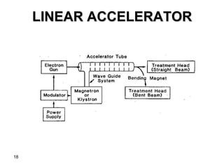
2. KILOVOLTAGE UNITS
• Up to about 1950
• X-rays generated at voltages up to 300 kVps
• Still some use in the present era, esp. treatment of
superficial skin lesions
• Kilovoltage Therapy
– Grenz-Ray Therapy
– Contact Therapy
– Superficial Therapy
– Orthovoltage Therapy or Deep Therapy
– Supervoltage Therapy
2
5. CONTACT THERAPY
– Energy: 40 – 50 kV
– Short SSD (< 2 cm)
– Produces a very rapidly decreasing depth dose
– Max irradiated tissue : skin surface
– Application: Tumor not deeper than 1 – 2 mm
– Endocavitary x ray machines have been used in the
treatment of superficial rectal cancers.
5
6. SUPERFICIAL THERAPY
– Energy: 50 – 150 kV
– HVLs: 1.0 – 8.0 mm Al
– Applicator or cone attached to the diaphragm
– SSD: 15 – 20 cm
– Tube current: 5 – 8 mA
– Application: tumors confined to about 5-mm depth
6
7. ORTHOVOLTAGE THERAPY
OR DEEP THERAPY
– Energy: 150 – 500 kV
– Tube current: 10 – 20 mA
– Cones or movable diaphragm (continuous
adjustable field size)
7
8. – SSD: 50 cm
– Application: tumor located < 2 –3 cm in depth
– Limitation of the treatment:
• skin dose
• Depth dose distribution
• Increase absorbed dose in bone
• Increase scattering
8
10. SUPERVOLTAGE THERAPY
– Energy: 500 – 1000 kV
– Technical problem
• Insulating the high-voltage transformer.
• Conventional transformer systems were not
suitable for producing potential > 300 kVp
– The problem solved by invention of resonant
transformer
10
11. – Used to generate x-rays from 300 to 2000 kV
11
At resonant frequency
1. Oscillating potential attains very high amplitude
2. Peak voltage across the x-ray tube becomes very large
RESONANT TRANSFORMER
UNITS
12. MEGAVOLTAGE THERAPY
• X-ray beams of energy > 1 MV
• Accelerators or γray(>1 Mev) produced by radionuclides
• Examples of clinical megavoltage machines
– Van de Graaff generator
– Linear accelerator
– Betatron
– Microtron
– Teletherapy γray units (e.g. cobalt-60)
12
13. VAN DE GRAAFF
GENERATOR
• Electrostatic accelerator-
accelerate charged particles
• Energy of x-rays: 2 MV (typical), up
to 10 MV
• Limitation:
– size
– high-voltage insulation
• No longer produced commercially
– Technically better machine (e.g.
Co-60 units & linear
accelerators)
13
14. LINEAR ACCELERATOR
• Use high frequency electromagnetic waves to accelerate
charged particles (e.g. electrons) to high energies
through a linear tube.
– High energy electron beam – treating superficial
tumors
– X rays- treating deep seated tumors
They use travelling or stationary electromagnetic
waves to accelerate electrons with frequency in the
microwave region.
14
15. • Types of EM wave
1. Traveling EM wave
• Required a terminating (“dummy”) load to absorb the
residual power at the end of the structure
• Prevent backward reflection wave
2. Standing EM wave
• Combination of forward and reverse traveling waves
• More efficiency
• More expensive
– Requires installation of a circulator (or insulator)
between the power source
– the structure prevent reflections from reaching the
power source
15
LINEAR ACCELERATOR
16. • POWER SUPPLY- Provides direct current to the
modulator
• MODULATOR- Pulse forming network which are
delivered to magnetron or klystron and simultaneously to
electron gun.
• MAGNETRON/KLYSTRON- Produce microwaves
• ACCELRATOR TUBE- Electrons interact with
electromagnetic field produced by microwaves and gain
energy
16
17. • LOW ENERGY LINACS- Electrons proceed
straight and strike target to produce x ray beam
• HIGH ENERGY LINACS- Electrons are bent
through a suitable angle with the help of beam
transport system consisting of bending magnets
and focussing coils.
17
20. THE MAGNETRON
• A device that produces microwaves
• Functions as a high-power oscillator
• Generating microwave pulses of several microseconds
with repetition rate of several hundred pulses per second
• Frequency of microwave within each pulse is about 3000
MHz
• Peak power output:
– 2 MW (for low-energy linacs, 6MV or less)
– 5 MW (for higher-energy linacs, mostly use klystrons)
20
21. 21
The cathode is heated by an inner filament
Electrons are generated by
thermionic emission
Static B-field perpendicular to the plane of cavities
Electron move in complex spirals toward the resonant cavities
Radiating energy in form of microwave
Pulse E-field between cathode & anode
Electron accelerated toward the anode
22. THE KLYSTRON
• Not a generator of microwaves
• Microwave amplifier
– Needs to be driven by a low-power microwave
oscillator
22
23. 23
The Klystron
Electrons produced by the cathode
Electrons are accelerated by –ve pulse
into buncher cavity
Lower level microwave set up an
alternating E field across the buncher
cavity
Velocity of e- is altered by the action
of E-field (velocity modulation)
1. Some e- are speed up
2. Other are slowed down
Passed in the drift tube
(field-free space)
Electrons arrive catcher cavity
1. Generate a retarding E-field
2. Electrons suffer
deceleration
3. KE of electrons converted
into high-power
microwaves
24. THE LINAC X-RAY BEAM
• Production of x-rays
– Electrons are incident on a target of a high-Z material
(e.g. tungsten)
– Target – need water cooled & thick enough to absorb
most of the incident electrons
– Bremsstrahlung interactions
• Electrons energy is converted into a spectrum of x-rays
energies
• Max energy of x-rays = energy of incident energy of electrons
• Average photon energy = 1/3 of max energy of x-rays
24
25. ELECTRON BEAM
• 3 mm diameter pencil beam of electrons
• In electron mode, beam strikes scattering foil
instead of target to spread the beam
• The thickness is such that most of the electrons
are scattered instead of producing
brehmsstrahlung.
• A small fraction still gets converted to x rays
• A secondary z foil of variable thickness to flatten
the electron beam
25
26. TREATMENT HEAD
26
26
Consists of a thick shell of
high density shielding material such
as lead, tungsten or lead-
tungsten alloy
27. FLATTENING FILTER
• Linacs produce electrons in megavoltage range,
hence x ray intensity is peaked in forward
direction.
• Flatting filter- makes intensity uniform across the
field
• Usually made of lead
27
28. 28
BEAM COLLIMATION AND
MONITORING
• In x rays, beam is first collimated by fixed
primary collimator
• The flattened beam is then incident on the dose
monitoring chambers.
– Consists of several ion chambers
– Or single chamber with multiple plates
– Monitor dose rate, integrated dose and field
symmetry
– Normally shielded so that response isnt
influenced by temperature and pressure of
outside air
29. • Beam is further collimated by continuously
movable x ray collimator
– 2 pairs of blocks of lead and tungsten(jaws)
– Rectangular opening from 0 x 0 to 40 x 40cm
– Modern collimators have multileaf
29
30. • Field size definition is provided by light localizing
system in the treatment head.
• Electrons scatter readily in air, hence beam
collimation is achieved close to the skin surface
• Dose rate is affected with increase in field size
• Problem is solved by opening the x ray
collimator to maximum size and attaching an
auxillary collimator for electrons in form of
trimmers extended down to the skin surface
30
32. BETATRON
• Electron in a changing magnetic field
experiences acceleration in a circular orbit
32
Energy of x-rays:
6 – 40 MV
Disadvantage:
low dose rate
Small field size
33. MICROTRON
• Electron accelerator which combines the principles of
both linear accelerator and the cyclotron.
• Electrons are accelerated by the oscillating field of one
or more microwave cavities.
33
Advantage:
Easy energy selection, small beam energy spread
and small size
34. CYCLOTRON
• Charged particle accelerator
• Mainly used for nuclear physics research
• As a source of high-energy protons for proton beam
therapy
• Have been adopted for generating neutron beams
recently
34
35. CYCLOTRON
35
Structures
• Short metallic cylinder divided into two section (Ds)
• Highly evacuated
• Placed between the poles of a direct current magnet
• Alternating potential is applied between two Ds
36. CYCLOTRON
36
Positive charged particles (e.g. protons or deuterons) are
injected at the center of the two Ds
Under Mag-field, the particles travel in a circular orbit
Accelerated by E-field while passing from one D to the other
Received an increment of energy
Radius of its orbit increases
37. MACHINES USING
RADIONUCLIDES
• Radionuclides have been used as source of γrays for
teletherapy
• Radium-226, Cesium-137, Cobalt-60
• 60Co has proved to be most suitable for external beam
R/T
• Higher possible specific activity
• Greater radiation output
• Higher average photon energy
37
38. COBALT-60 UNIT
• Source
– From 59Co(n, γ) nuclear reactor
– Stable 59Co → radioactive 60Co
– In form of solid cylinder, discs, or pallets
• Treatment beam
60Co →60Ni + 0β(0.32 MeV) + γ(1.17 & 1.33 MeV)
• Heterogeneity of the beam
– Secondary interactions
– βabsorbed by capsule → bremsstrahlung x-rays
(0.1MeV)
– scattering from the surrounding capsule, the source
housing and the collimation system (electron
contamination)
38
39. SOURCE HOUSING
• Called sourcehead
• Steel shell filled with lead for shielding purposes
• A device for bringing source in front of opening
• A heavy metal alloy sleeve is provided to form
additional primary shield when source is in the
off position.
39
40. • Methods to move source from off to on postion
– Source mounted on a rotating wheel
– Source mounted on a heavy metal drawer
– Mercury is allowed to flow in the space
immediately below the source
– Source is fixed in aperture and beam is turned
off with shutter consisting heavy metal jaws
40
42. PENUMBRA
• The region, at the edge of a radiation beam, over which
the dose rate changes rapidly as function of distance
from the beam axis
1. Transmission penumbra
2. Geometric penumbra
42
43. • Transmission penumbra
– If the inner surface of the blocks is made
parallel to the central axis of the beam
– The radiation will pass through the edge of
the collimating blocks Transmission
Penumbra
– The extent of this penumbra will be more
pronounced for larger collimator opening
43
45. 45
From considering similar
triangles ABC and DEC
DE = CE = CD = MN = OF + FN – OM
AB CA CB OM OM
AB = s (source diameter)
OF = SSD
DE = Pd ( penumbra)
Pd = s (SSD + d – SDD)
SDD
Parameters determine the width of
penumbra
• Geometric penumbra
• Radiation source: not a point source
– e.g. 60 Co teletherapy → cylinder of diameter
ranging from 1.0 to 2.0 cm
46. 46
• Geometric penumbra (con’t)
– Solutions
• Extendable penumbra trimmer
– Heavy metal bars to attenuate the beam in the penumbra
region
• Secondary blocks
– Placed closed to the patient for redifining the field
– Should not be placed < 15 – 20 cm, excessive electron
contaminants
– Definition of physical penumbra in dosimetry
• Lateral distance between two specified isodose
curves at a specified depth
– At a depth in the patient, dose variation at the field border
– Geometric, transmission penumbras + scattered
radiation produced in the patient
47. HEAVY PARTICLE BEAMS
• Advantage
– Dose localization
– Therapeutic gain (greater effect on tumor than on
normal tissue)
• Including
– neutrons, protons, deuterons, αparticles, negative
pions, and heavy ions
• Still experimental
• Few institutions because of the enormous cost
47
48. NEUTRONS
• Sources of high energy neutron beams
– D-T generator, cyclotrons, or linear accelerators
• D-T generators
2H + 3H → 4He + 1n + 17.6 MeV
1 1 2 0
– Monoenergetic (14 MeV)
– Isotropic (same yield in all directions)
– Major problem
• Lack of sufficient dose rate at the treatment distance
• 15 cGy/min at 1 m
– Advantage
• Its size is small enough to allow isocentric mounting on
gantry
48
49. • Cyclotron
– Stripping reaction
2
H + 9
Be → 10
Be + 1
n
1 4 5 0
– Mostly in forward
direction
– Spectrum of energies
(average neutron
energy is 40% - 50%
of deuteron energy)
49
Fig 4.15. Neutron spectra produced by
deuterons on beryllium target
50. PROTONS AND HEAVY IONS
• Energy of therapeutic proton beams
– 150 – 250 MeV
• Sources: produced by cyclotron or linear accelerator
• Major advantage
– Characteristic distribution of dose with depth. Dose
deposited is approximately constant with depth until
the end where dose peaks out to a high value with a
rapid fall off to zero.
50
52. NEGATIVE PIONS
• Pi meson (pion, π)
– Protons and neutrons are held together by a mutual
exchange of pi mesons
– Mass : 237x of electron
– Charge : π+, π-, π0
– Decay: π+ → μ+ + ν (mean life: 2.54 x 10⁻¹⁸)
π- → μ- + ν (mean life: 2.54 x 10⁻¹⁸)
π0 → hν1 + hν2(mean life: 2.54 x 10⁻¹⁸)
μ— mesons; ν — neutrinos
52
53. 53
– Sources:
• nuclear reaction
• Cyclotron or linear accelerator with protons (400 – 800 MeV)
and beryllium as target material
– Energy range of pion interest in R/T — 100 MeV
– Range in water about — 24 cm
– Problems
• Low dose rates
• Beam contamination
• High cost