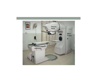
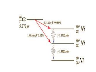
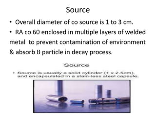
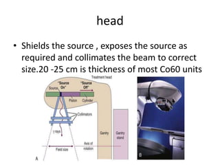
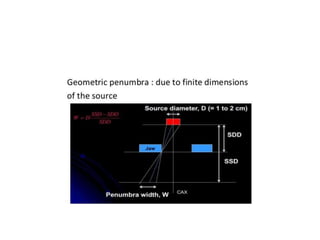
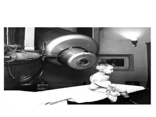
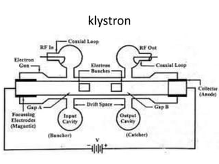
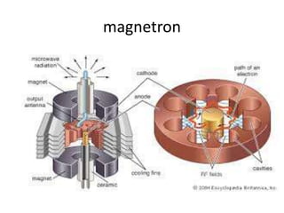
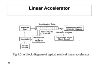
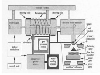
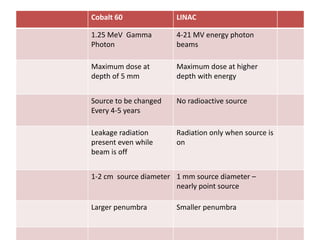
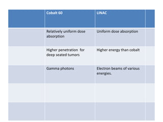
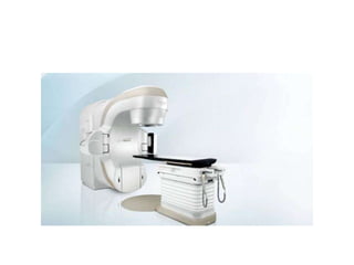
Tele therapy Equipment s and
Sources
By Dr. Atmaram Choudhari.
Tele therapy
• Treatment in which is source of therapy is some
distance from body.
• Tele therapy is divided into kilo voltage & mega
voltage therapy depending upon the beam
quality .
• Kilo voltage-A. contact therapy .
B . superficial therapy.
C . Ortho voltage or deep therapy
Contact therapy
• 40-50 KV small focal spot short SSD approx.
2 cm. source to surface distance.
• Absorbed within 2 cm of tissue.
• SSD 2cm or less.
• Used for tumors less than 1 to 2 mm in
thickness
Superficial therapy
• Treatment of x rays produced with energy of
50-150 kV.
• Source to skin distance 15 to 20 cm.
• Used to tumors of about 5 mm.
• beyond this dose fall off too sharp to deliver
adequate dose.
Ortho voltage or deep therapy
• 150-500kv .
• Treatment field used to be defined using
detachable cones.
• The SSD was typically 50 cm.
• Not in use higher skin dose unsuitable dose
distribution greater bone absorption,
increased scatter.
Super voltage therapy
• X ray therapy in range of 500-1000 KV .
• Due to demand of deeper tumors of these
were created.
Mega voltage therapy
• X ray beam of energy of 1 MV or greater.
• Van de Graff generators, radionuclides with
gamma rays of 1 MeV or greater used.
Van de Graff generator
• Electrostatic accelerator used to accelerate
charged particles.
• Typically 20 -40 KV is applied to moving belt of
insulator.
• The electrons are carried to top of belt and
are removed by a collector.
• A large collection of negative is accumulated
at the top of dome.
• When applied across X ray tube. This allows
production of x rays when electron hit the
target.
• Van de Graff generator is capable of reaching
energy of 10 MeV but limited by insulation by
size . Not used due to cobalt 60 and linacs.
Betatron
• Electron in circular magnetic field accelerate in
in circular orbit.
• An electron pulse is introduced into donut
between poles of magnet of ac current.
• Not used due to small field size and dose rate
capabilities.
Micro tron
• Electrons are accelerated by oscillating fields
of 1 or more microwave cavities.
Then magnetic field forces to electron to orbit in
circular cavity
Lower electric consumption.
Simpler cooling system.
Low cost.
cyclotron
• Charged particle accelerator
• High frequency high voltage oscillator used to
accelerate charged particle.
Used as source energy proton beam therapy
Using radionuclides
• Cesium-137
• Radium -226
• Cobalt-60.
cobalt 60 is suitable for EBRT-
higher photon energy
greater radiation output per curie.
Cobalt-60
• 59 Co is irradiated with neutrons in reactor .
• Can take 5 -10 years to produce.
• First done in London, Canada.
Source
• Overall diameter of co source is 1 to 3 cm.
• RA co 60 enclosed in multiple layers of welded
metal to prevent contamination of environment
& absorb B particle in decay process.
•
head
• Shields the source , exposes the source as
required and collimates the beam to correct
size.20 -25 cm is thickness of most Co60 units
Source shielding
• Consist of steel shell with lead for shielding
purposes and a mechanism for bringing
source in front of the collimator opening to
produce the clinical gamma rays.
• The source moves from beam on region to
beam off region by either:
1 a source on sliding drawer and
2. source on a rotating cylinder.
• 3. mercury allowed to flow into space below
the source to shut off the beam.
• 4. Source fixed in front of the aperture and
beam turned off and on by shutter of heavy
metal jaws.
Collimator and penumbra
• Collimator provide square and rectangular
radiation fields typically ranging from 5*5 cm
to 35*35 cm at 30 cm from source .
• The geometric penumbra which results from
finite source diameter may be minimized by
small diameter sources and by using
penumbra trimmers as close as possible to the
patients skin.
Gantry
• The thing that moves around Iso-centric point
is the gantry.
• Iso centric (the point of intersection of
collimator axis and axis of rotation gantry).
Can rotate 360 degrees around gantry axis
• Once set the SSD distance does not change
with movement of gantry.
Linac
• The device that uses high frequency electro
magnetic waves to accelerate charged
particles such as electrons through high
energies through linear tube.
• The high energy tube itself used to treat
superficial tumors or it can be made to strike
target to produce X rays for treating deep
seated tumours.
• 1st one was installed in Hammersmith London
in 1952.
• X ray of 8 MeV with limited gantry movement.
2nd generation linac.1952-62
• iso centric (the point of intersection of
collimator axis and axis of rotation gantry).
Can rotate 360 degrees around gantry axis.
3rd generation
• Better accelerator waveguides and bending
magnet system and more beam modifying
system
components
• Modular cabinet
• Console
• Drive stand-1.klystron.2.wave guide 3.
• Gantry-1. electron gun
2.accelerator structure.
• Treatment head-bending magnet.2.flattening
filter3.Scatter foil.4.Xray target 5.collimator.
Modular cabinets
• Contains components that distribute power
and monitor power to magnetron / klyestron
in treatment room.
console
• Central mechanism-digital display , push
button panel , video display terminal.
• Display for dose ,collimator setting gantry
angle.
klystron
magnetron
Gantry
• Directing photons or X rays at a patients
tumor.
• Electron gun –produces and injects electron in
accelerator
head
• Bending magnets-directs e vertically to patient
• Target-x ray
• Primary collimator-limit maximum field size.
• Beam flattening filter-shape x ray in cross
sectional dimension
• Ion chamber-monitor dose rate ,field symmetry
• Secondary collimators.
• Slot for wedges blocks
Cobalt 60 LINAC
1.25 MeV Gamma
Photon
4-21 MV energy photon
beams
Maximum dose at
depth of 5 mm
Maximum dose at higher
depth with energy
Source to be changed
Every 4-5 years
No radioactive source
Leakage radiation
present even while
beam is off
Radiation only when source is
on
1-2 cm source diameter 1 mm source diameter –
nearly point source
Larger penumbra Smaller penumbra
Cobalt 60 LINAC
Relatively uniform dose
absorption
Uniform dose absorption
Higher penetration for
deep seated tumors
Higher energy than cobalt
Gamma photons Electron beams of various
energies.
• Thank you

Teletherapy equipments and

  • 1.
    Tele therapy Equipments and Sources By Dr. Atmaram Choudhari.
  • 2.
    Tele therapy • Treatmentin which is source of therapy is some distance from body. • Tele therapy is divided into kilo voltage & mega voltage therapy depending upon the beam quality . • Kilo voltage-A. contact therapy . B . superficial therapy. C . Ortho voltage or deep therapy
  • 3.
    Contact therapy • 40-50KV small focal spot short SSD approx. 2 cm. source to surface distance. • Absorbed within 2 cm of tissue. • SSD 2cm or less. • Used for tumors less than 1 to 2 mm in thickness
  • 4.
    Superficial therapy • Treatmentof x rays produced with energy of 50-150 kV. • Source to skin distance 15 to 20 cm. • Used to tumors of about 5 mm. • beyond this dose fall off too sharp to deliver adequate dose.
  • 5.
    Ortho voltage ordeep therapy • 150-500kv . • Treatment field used to be defined using detachable cones. • The SSD was typically 50 cm. • Not in use higher skin dose unsuitable dose distribution greater bone absorption, increased scatter.
  • 6.
    Super voltage therapy •X ray therapy in range of 500-1000 KV . • Due to demand of deeper tumors of these were created.
  • 7.
    Mega voltage therapy •X ray beam of energy of 1 MV or greater. • Van de Graff generators, radionuclides with gamma rays of 1 MeV or greater used.
  • 8.
    Van de Graffgenerator • Electrostatic accelerator used to accelerate charged particles. • Typically 20 -40 KV is applied to moving belt of insulator. • The electrons are carried to top of belt and are removed by a collector. • A large collection of negative is accumulated at the top of dome.
  • 10.
    • When appliedacross X ray tube. This allows production of x rays when electron hit the target. • Van de Graff generator is capable of reaching energy of 10 MeV but limited by insulation by size . Not used due to cobalt 60 and linacs.
  • 11.
    Betatron • Electron incircular magnetic field accelerate in in circular orbit. • An electron pulse is introduced into donut between poles of magnet of ac current. • Not used due to small field size and dose rate capabilities.
  • 13.
    Micro tron • Electronsare accelerated by oscillating fields of 1 or more microwave cavities. Then magnetic field forces to electron to orbit in circular cavity Lower electric consumption. Simpler cooling system. Low cost.
  • 15.
    cyclotron • Charged particleaccelerator • High frequency high voltage oscillator used to accelerate charged particle. Used as source energy proton beam therapy
  • 17.
    Using radionuclides • Cesium-137 •Radium -226 • Cobalt-60. cobalt 60 is suitable for EBRT- higher photon energy greater radiation output per curie.
  • 18.
    Cobalt-60 • 59 Cois irradiated with neutrons in reactor . • Can take 5 -10 years to produce. • First done in London, Canada.
  • 21.
    Source • Overall diameterof co source is 1 to 3 cm. • RA co 60 enclosed in multiple layers of welded metal to prevent contamination of environment & absorb B particle in decay process. •
  • 22.
    head • Shields thesource , exposes the source as required and collimates the beam to correct size.20 -25 cm is thickness of most Co60 units
  • 23.
    Source shielding • Consistof steel shell with lead for shielding purposes and a mechanism for bringing source in front of the collimator opening to produce the clinical gamma rays. • The source moves from beam on region to beam off region by either: 1 a source on sliding drawer and 2. source on a rotating cylinder.
  • 24.
    • 3. mercuryallowed to flow into space below the source to shut off the beam. • 4. Source fixed in front of the aperture and beam turned off and on by shutter of heavy metal jaws.
  • 25.
    Collimator and penumbra •Collimator provide square and rectangular radiation fields typically ranging from 5*5 cm to 35*35 cm at 30 cm from source . • The geometric penumbra which results from finite source diameter may be minimized by small diameter sources and by using penumbra trimmers as close as possible to the patients skin.
  • 28.
    Gantry • The thingthat moves around Iso-centric point is the gantry. • Iso centric (the point of intersection of collimator axis and axis of rotation gantry). Can rotate 360 degrees around gantry axis • Once set the SSD distance does not change with movement of gantry.
  • 29.
    Linac • The devicethat uses high frequency electro magnetic waves to accelerate charged particles such as electrons through high energies through linear tube. • The high energy tube itself used to treat superficial tumors or it can be made to strike target to produce X rays for treating deep seated tumours.
  • 30.
    • 1st onewas installed in Hammersmith London in 1952. • X ray of 8 MeV with limited gantry movement.
  • 32.
    2nd generation linac.1952-62 •iso centric (the point of intersection of collimator axis and axis of rotation gantry). Can rotate 360 degrees around gantry axis.
  • 33.
    3rd generation • Betteraccelerator waveguides and bending magnet system and more beam modifying system
  • 34.
    components • Modular cabinet •Console • Drive stand-1.klystron.2.wave guide 3. • Gantry-1. electron gun 2.accelerator structure. • Treatment head-bending magnet.2.flattening filter3.Scatter foil.4.Xray target 5.collimator.
  • 35.
    Modular cabinets • Containscomponents that distribute power and monitor power to magnetron / klyestron in treatment room.
  • 36.
    console • Central mechanism-digitaldisplay , push button panel , video display terminal. • Display for dose ,collimator setting gantry angle.
  • 37.
  • 38.
  • 39.
    Gantry • Directing photonsor X rays at a patients tumor. • Electron gun –produces and injects electron in accelerator
  • 41.
    head • Bending magnets-directse vertically to patient • Target-x ray • Primary collimator-limit maximum field size. • Beam flattening filter-shape x ray in cross sectional dimension • Ion chamber-monitor dose rate ,field symmetry • Secondary collimators. • Slot for wedges blocks
  • 43.
    Cobalt 60 LINAC 1.25MeV Gamma Photon 4-21 MV energy photon beams Maximum dose at depth of 5 mm Maximum dose at higher depth with energy Source to be changed Every 4-5 years No radioactive source Leakage radiation present even while beam is off Radiation only when source is on 1-2 cm source diameter 1 mm source diameter – nearly point source Larger penumbra Smaller penumbra
  • 44.
    Cobalt 60 LINAC Relativelyuniform dose absorption Uniform dose absorption Higher penetration for deep seated tumors Higher energy than cobalt Gamma photons Electron beams of various energies.
  • 46.