Downloaded 111 times
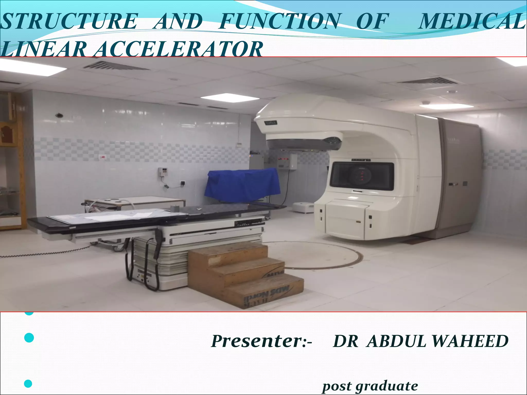
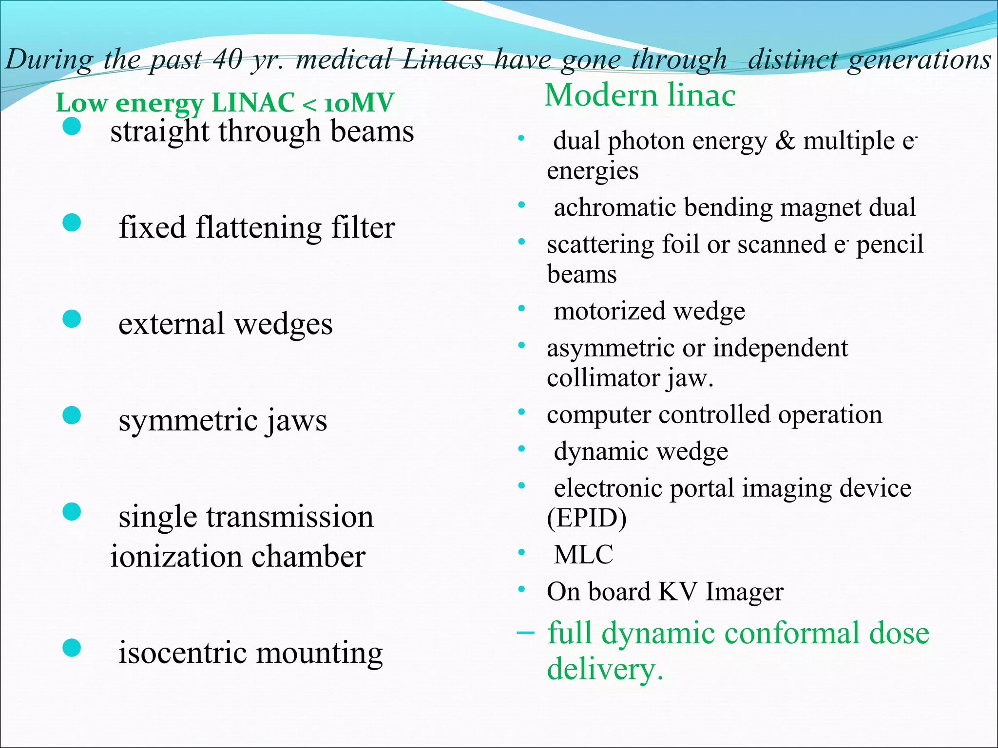


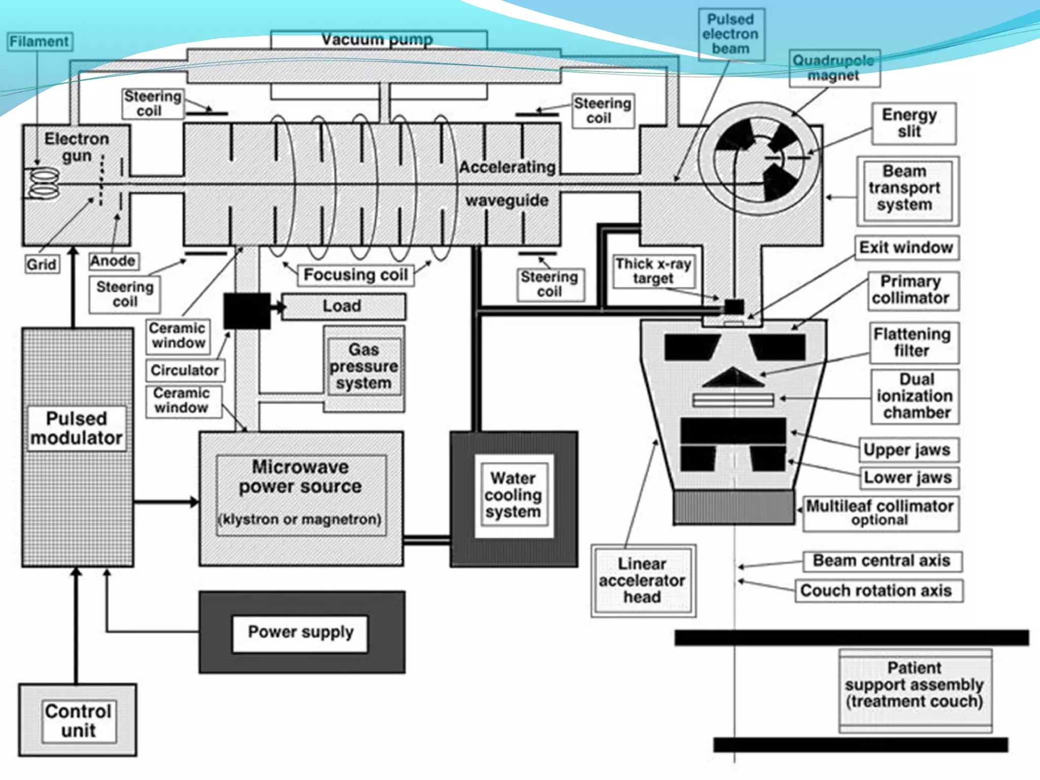


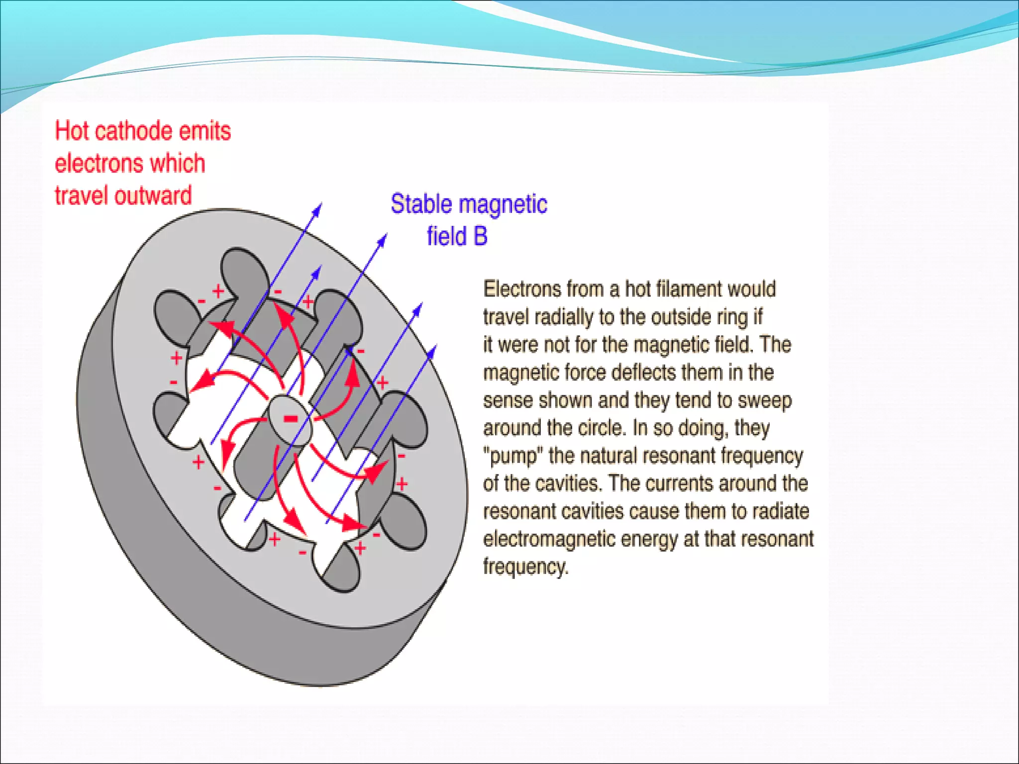


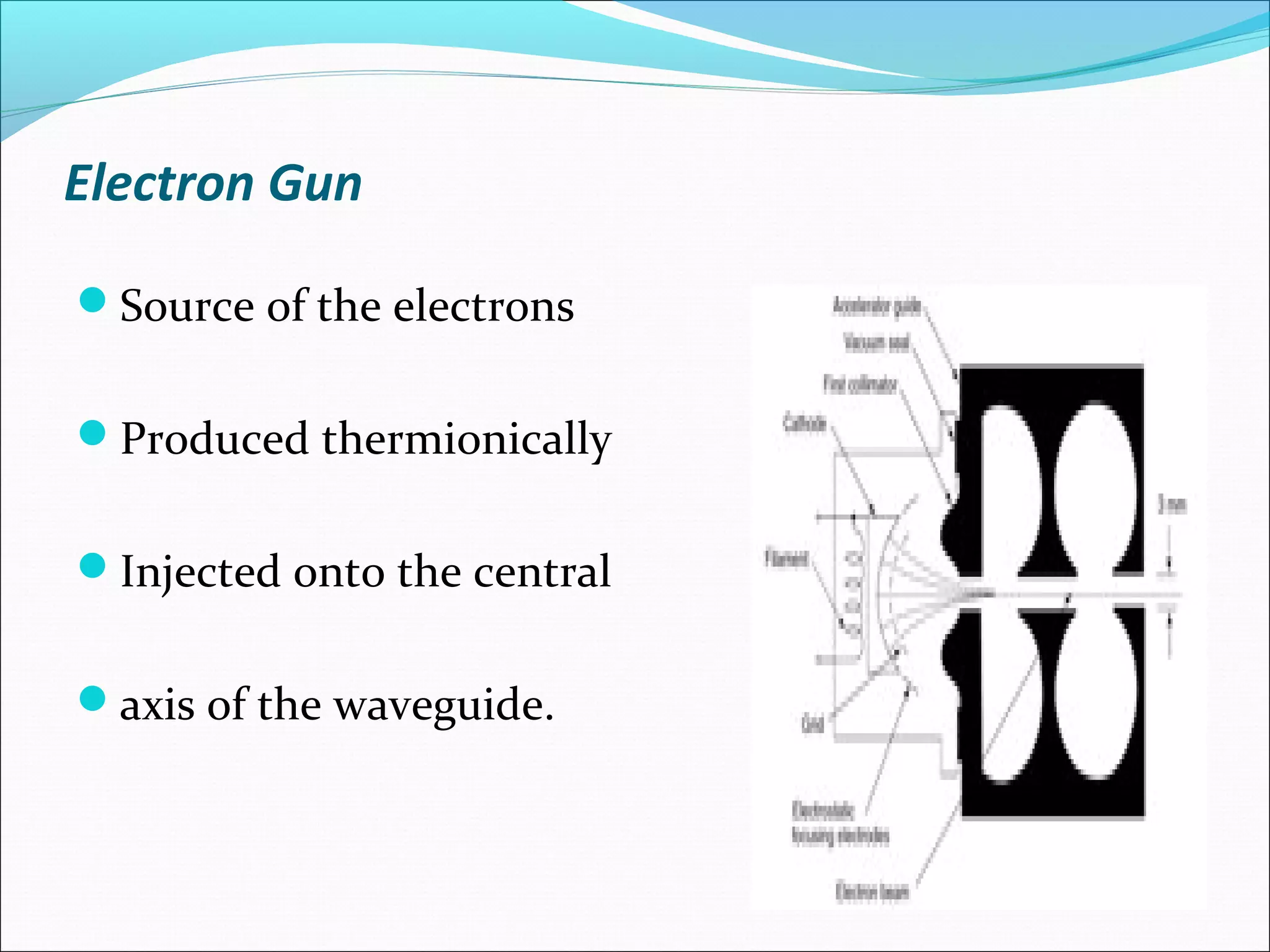


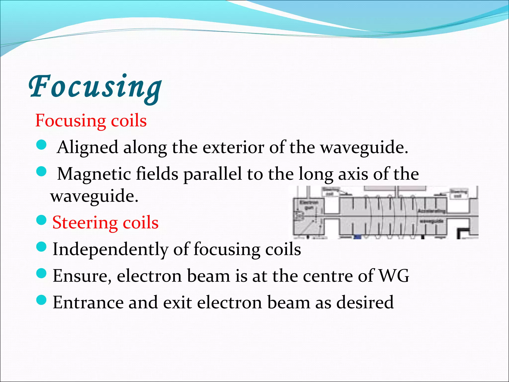

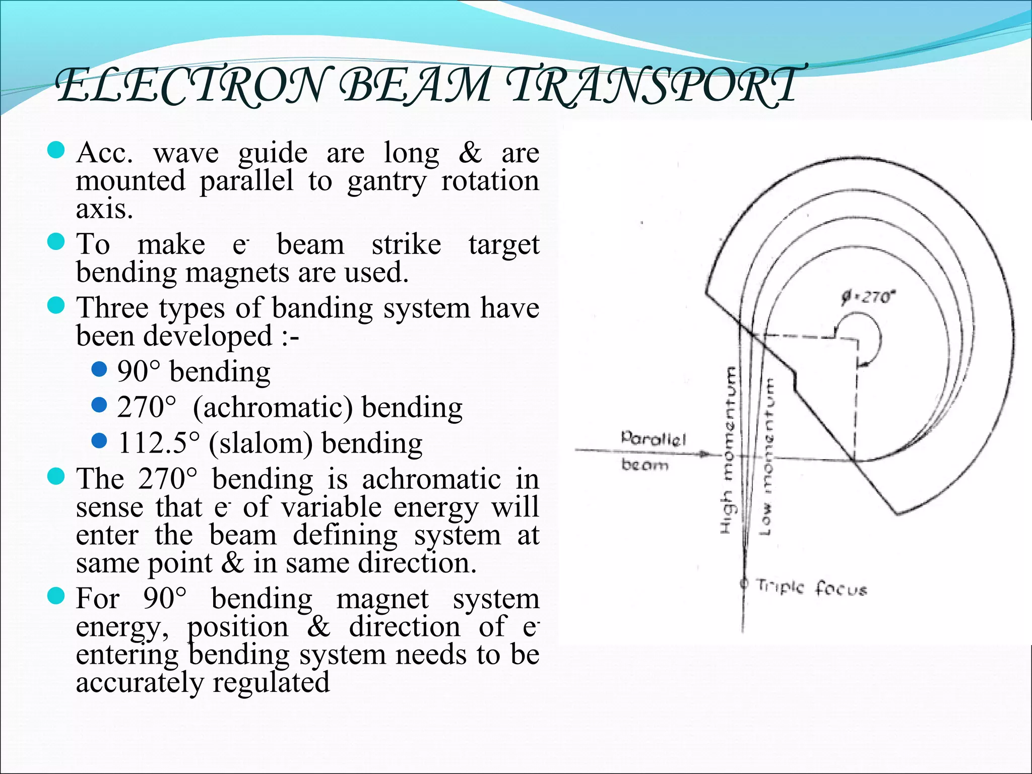
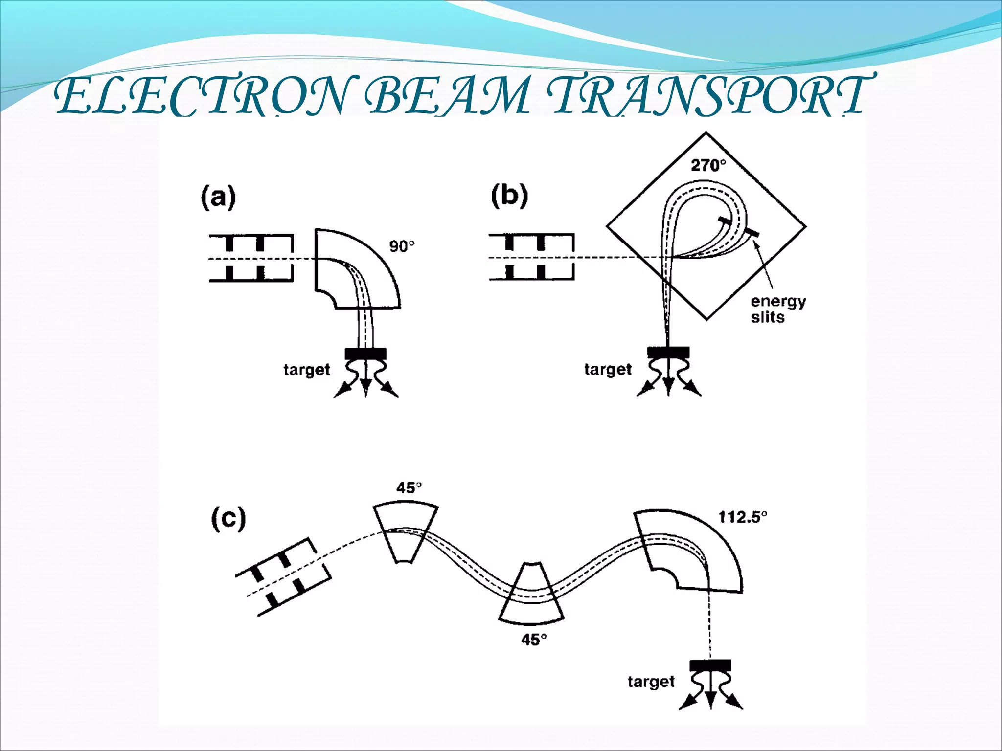


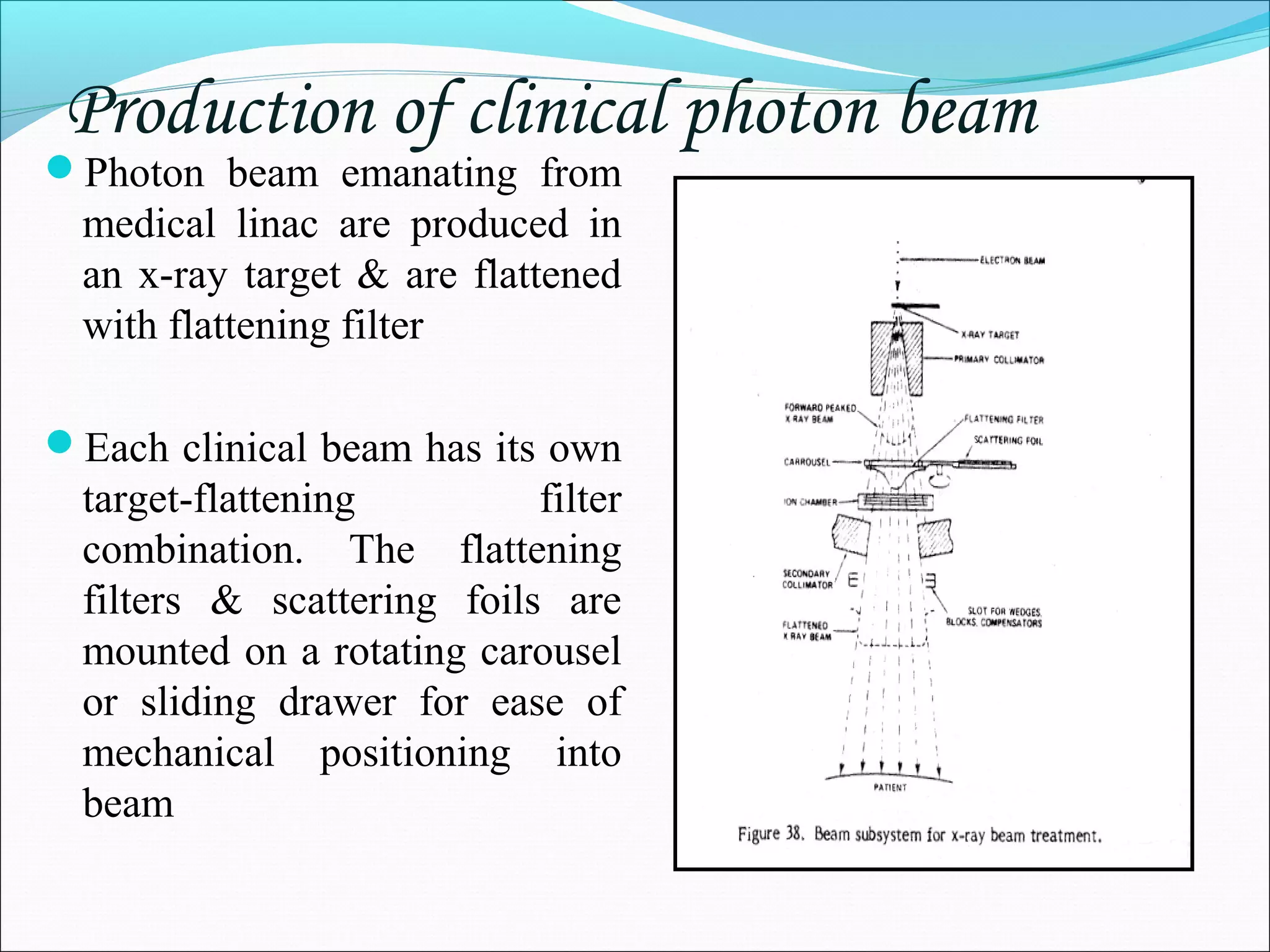
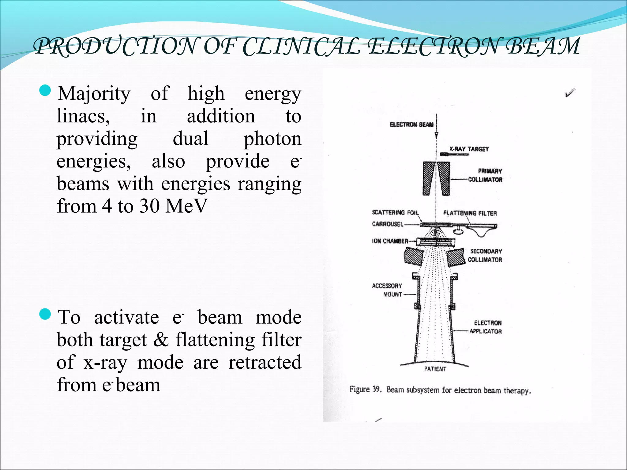

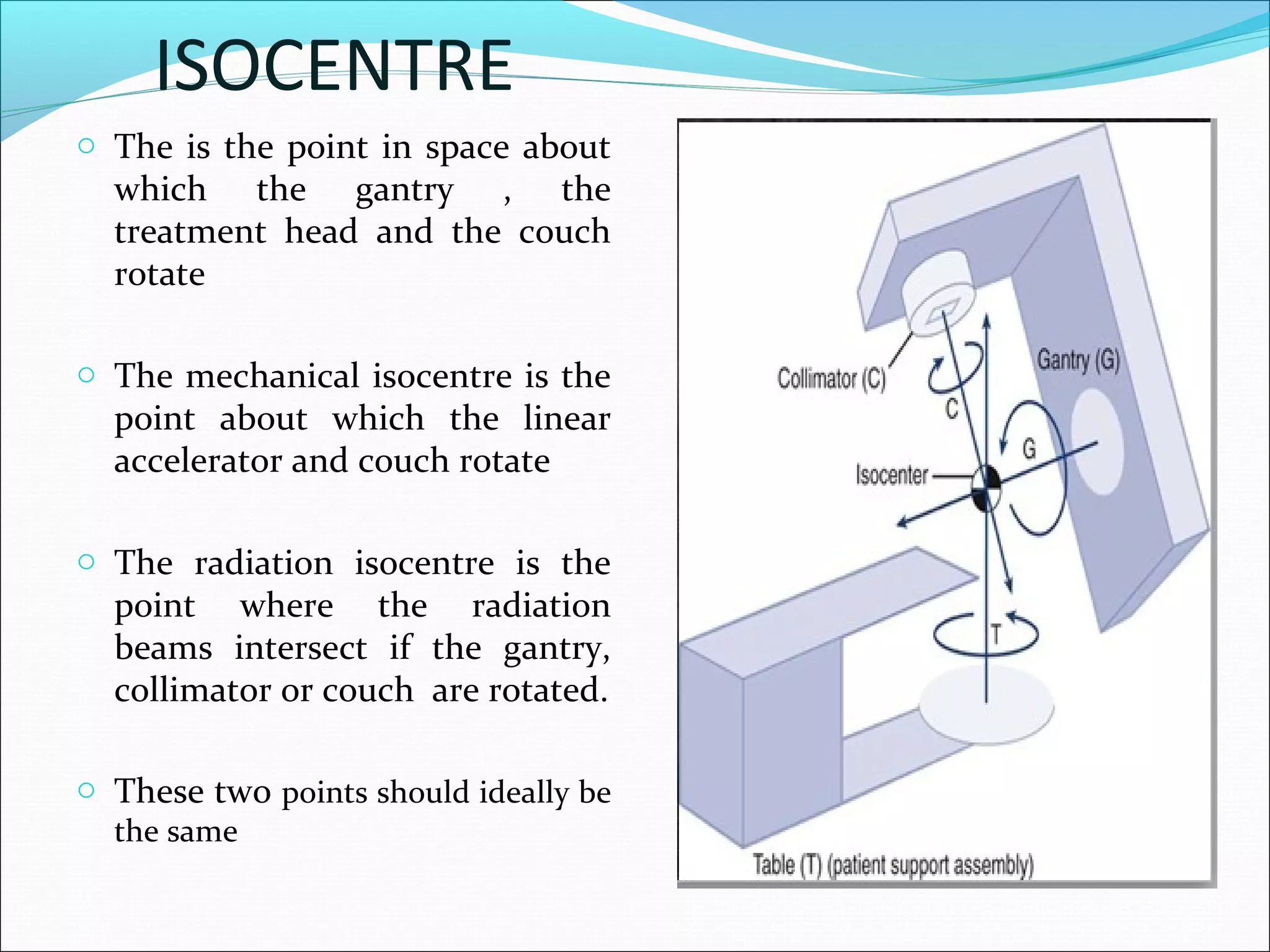


The document summarizes the structure and function of a medical linear accelerator (LINAC). It describes how a LINAC works by using high-frequency electromagnetic waves to accelerate electrons and produce x-rays or electron beams for radiation therapy. Key components of a LINAC include the electron gun, accelerating waveguide, bending magnet, and treatment head for beam shaping and targeting. Modern LINACs can produce multiple photon and electron beam energies for flexible radiation treatment options.


![[equipment iv] linacc](https://cdn.slidesharecdn.com/ss_thumbnails/sbmeequipmentivlinac-200915164740-thumbnail.jpg?width=640&height=640&fit=bounds)


