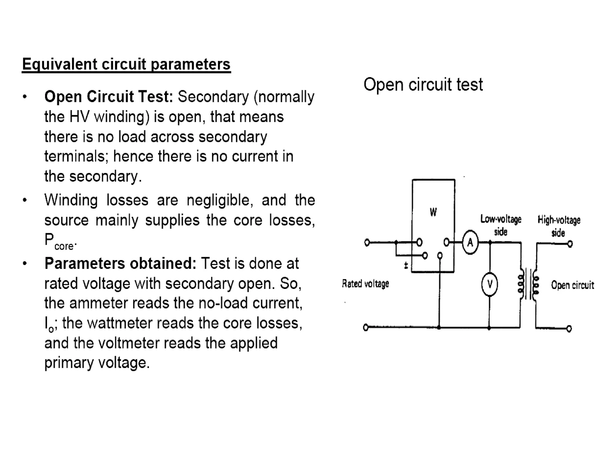
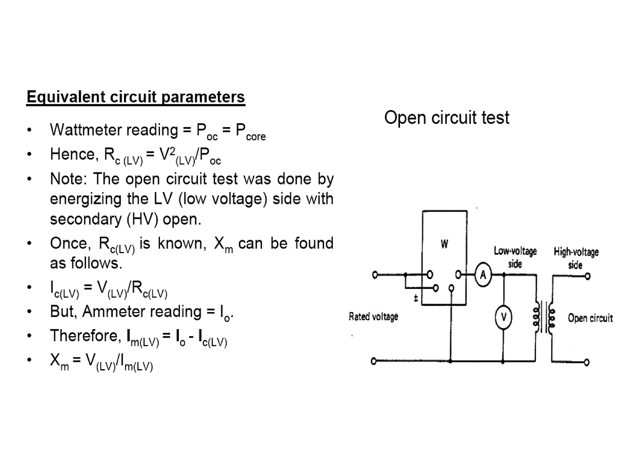
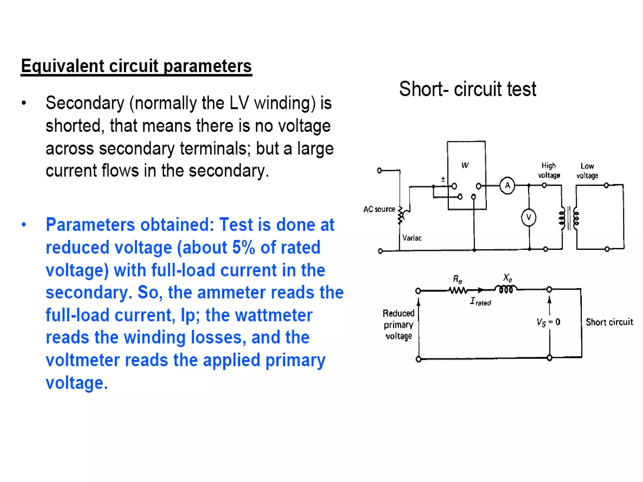
Downloaded 37 times
![Impedance transfer
• Impedance transfer helps to calculate the
current/voltage easier and get ride of the ratio for the
rest of the calculation.
• Looking into the circuit from source side, let us define the
impedance as Zin = Vp/Ip
• Looking into the circuit from load side (neglecting the load
itself), let us define the impedance as ZL = Vs/Is
• Relating Vp/Ip in terms of Vs/Is using the turns ration, a,
[Vp/Ip]= a2 [Vs/Is]
Zin = a2 ZL
• Hence, in general, any impedance transferred from
secondary side to primary side must be multiplied by the
square of the turns-ratio, a2.](https://image.slidesharecdn.com/e-sciencelesson101-121106034258-phpapp01/75/Engineering-science-lesson-10-1-16-2048.jpg)
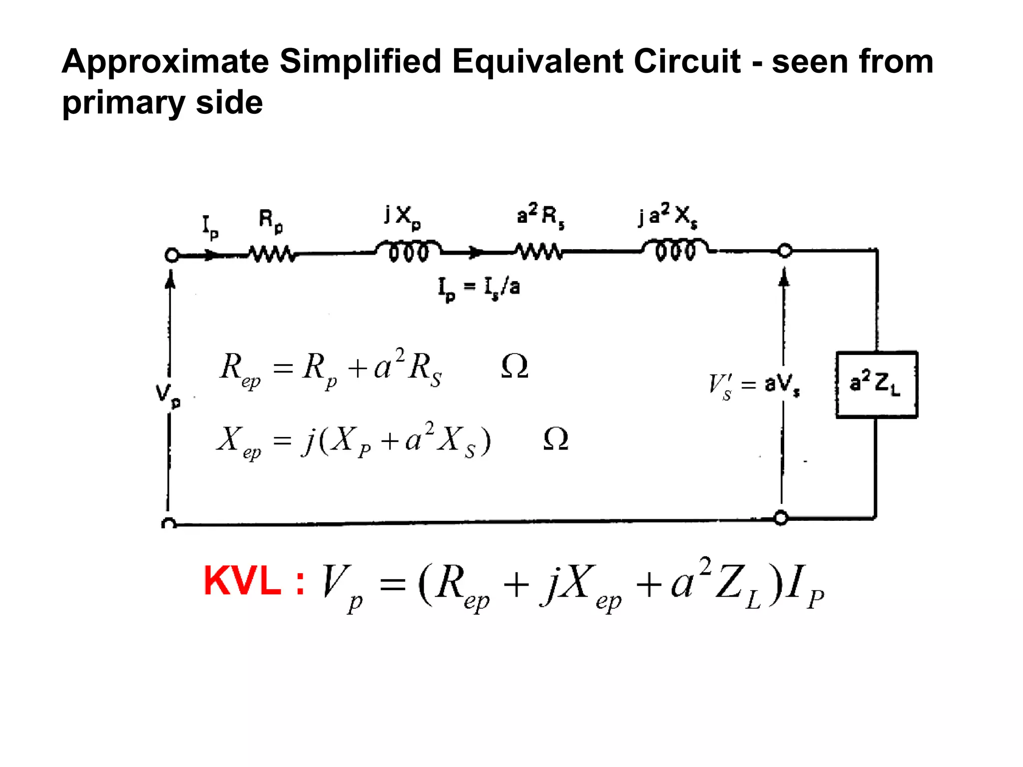
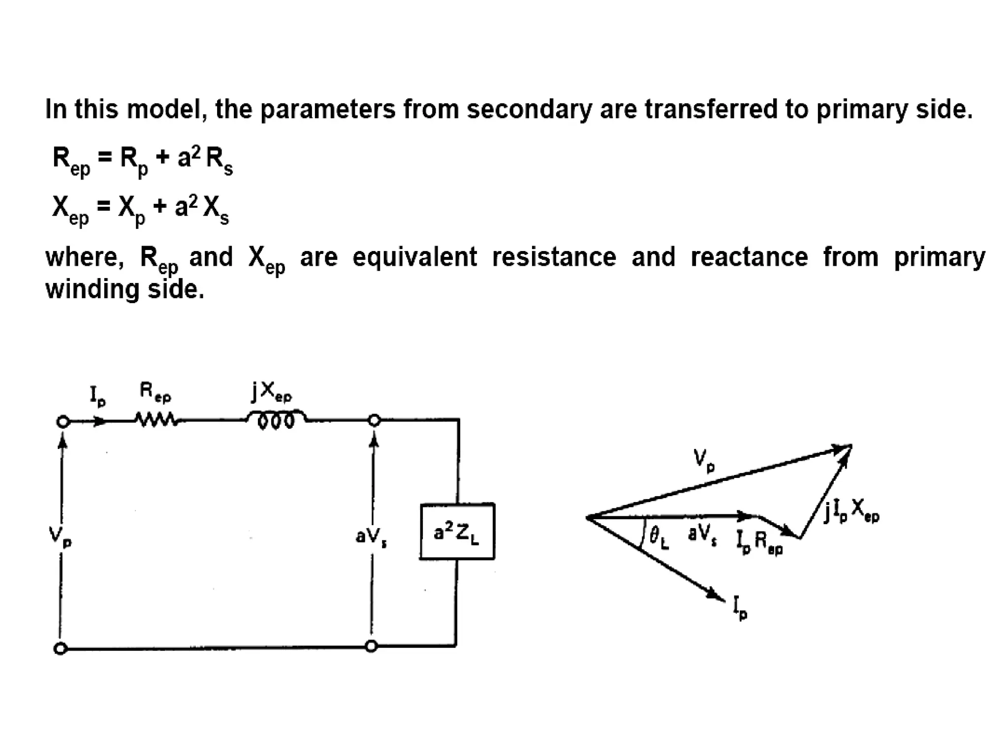

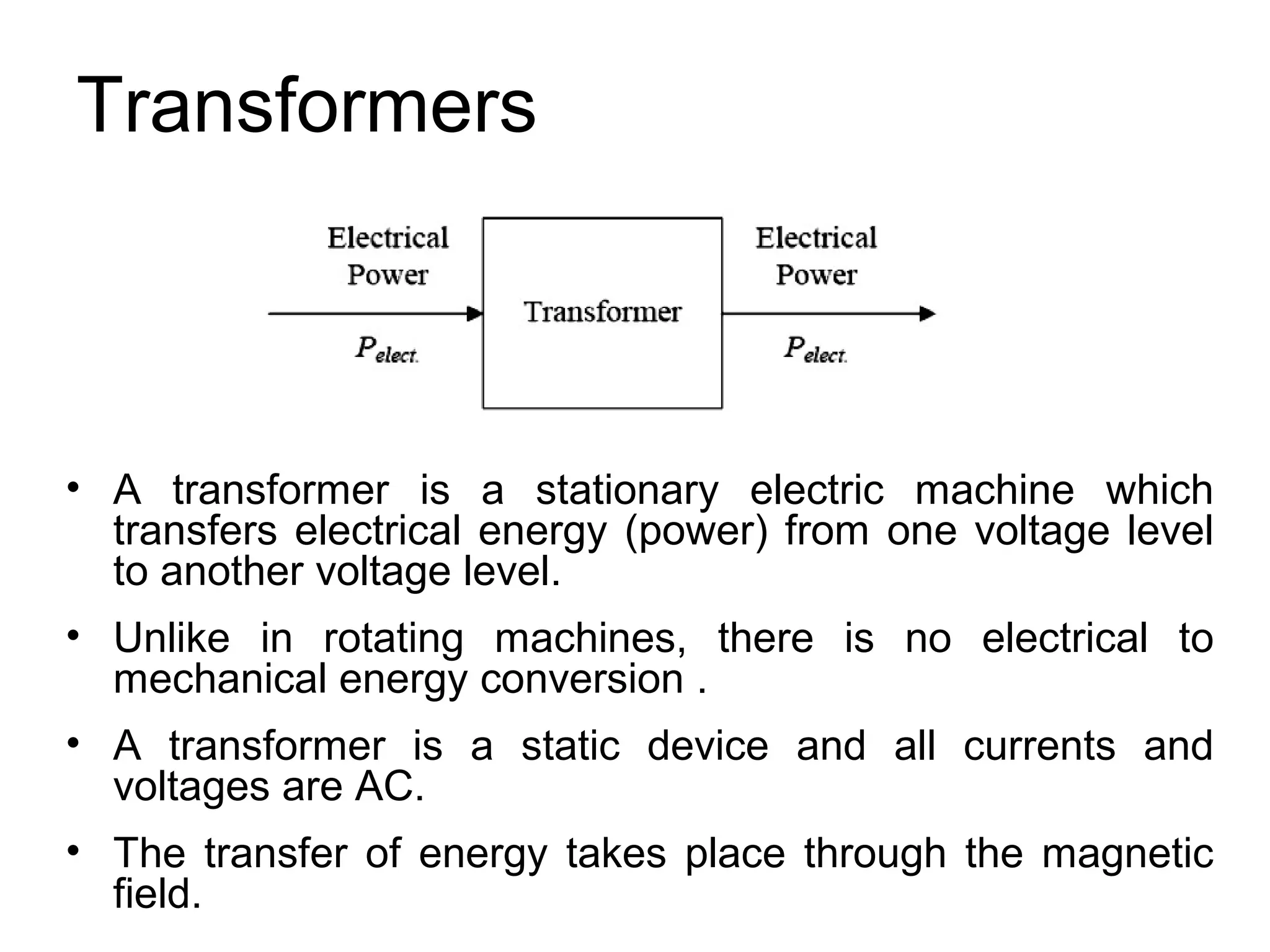
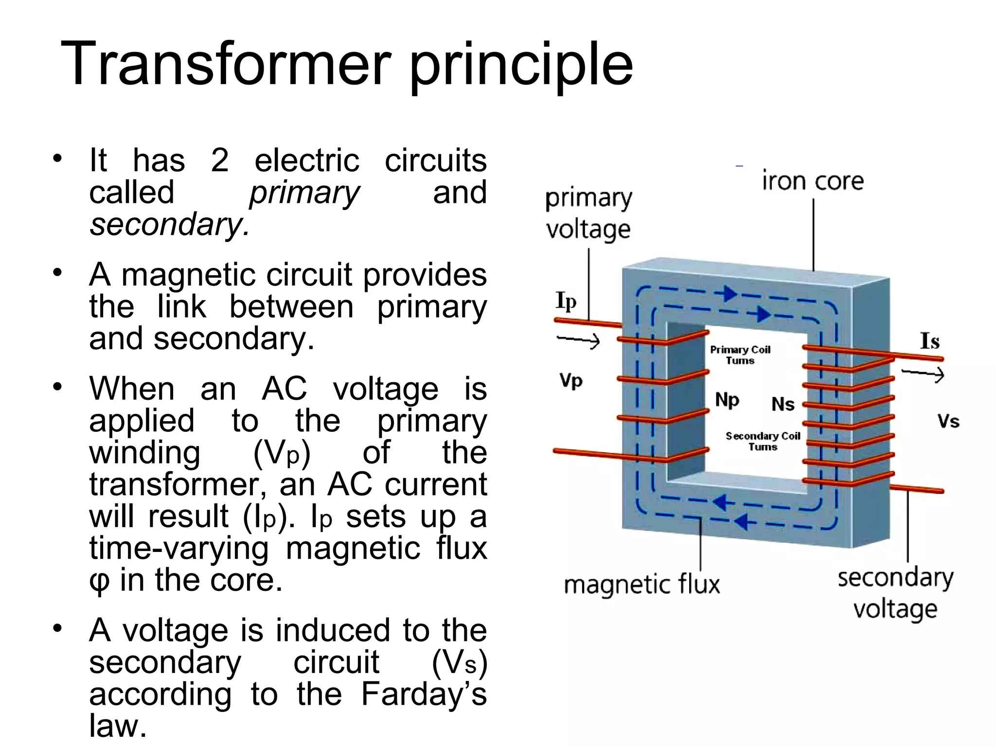
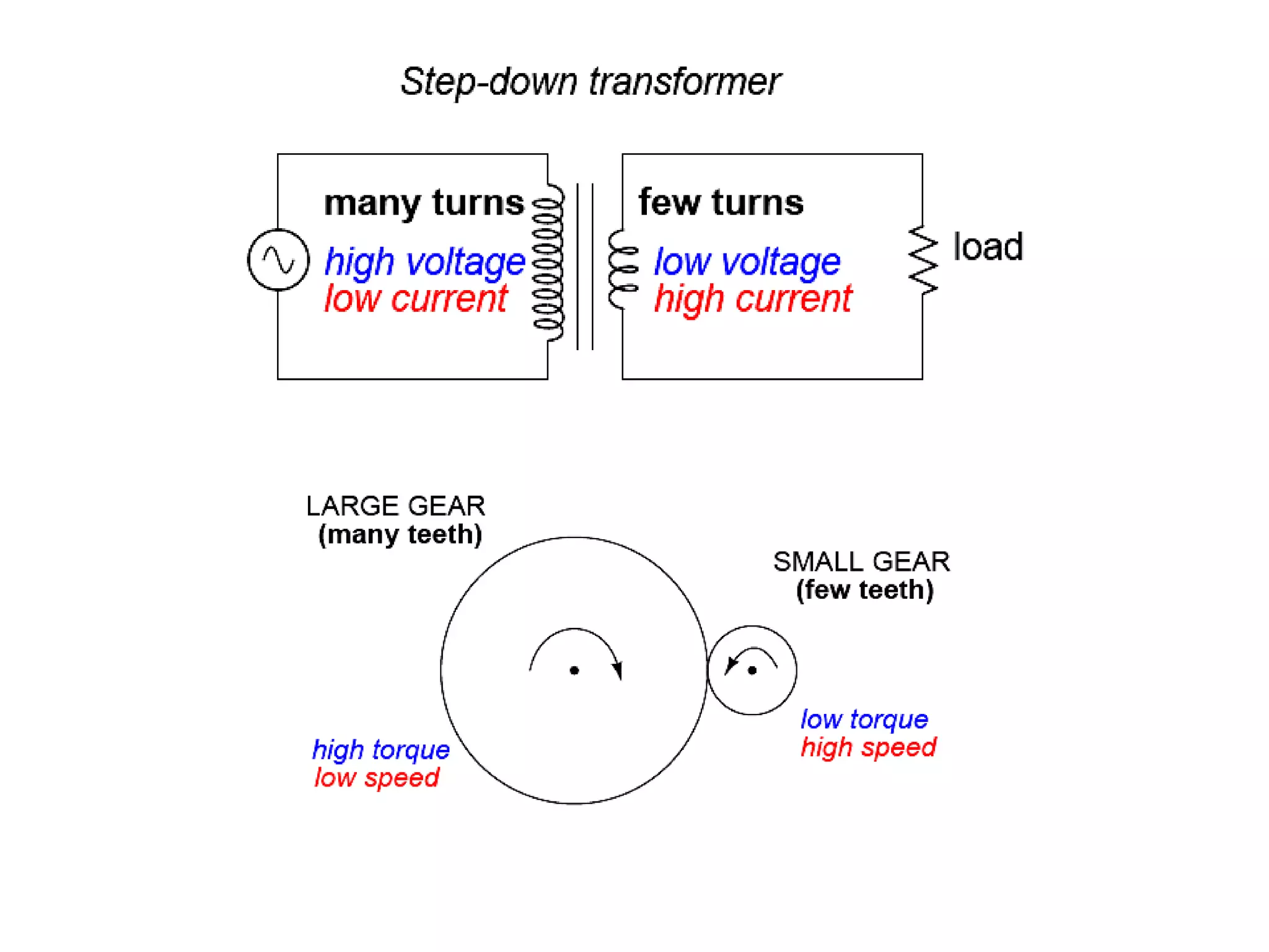
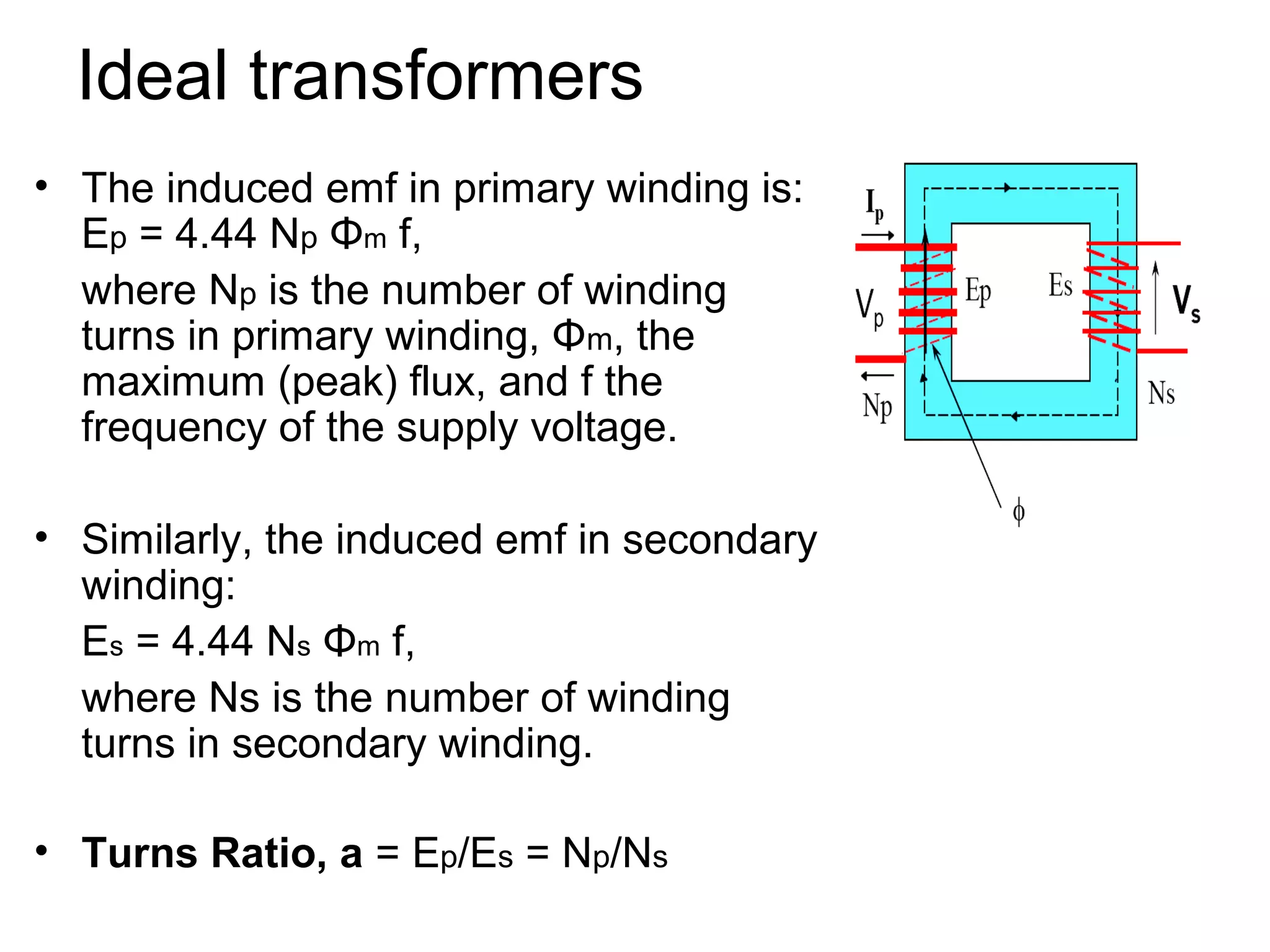
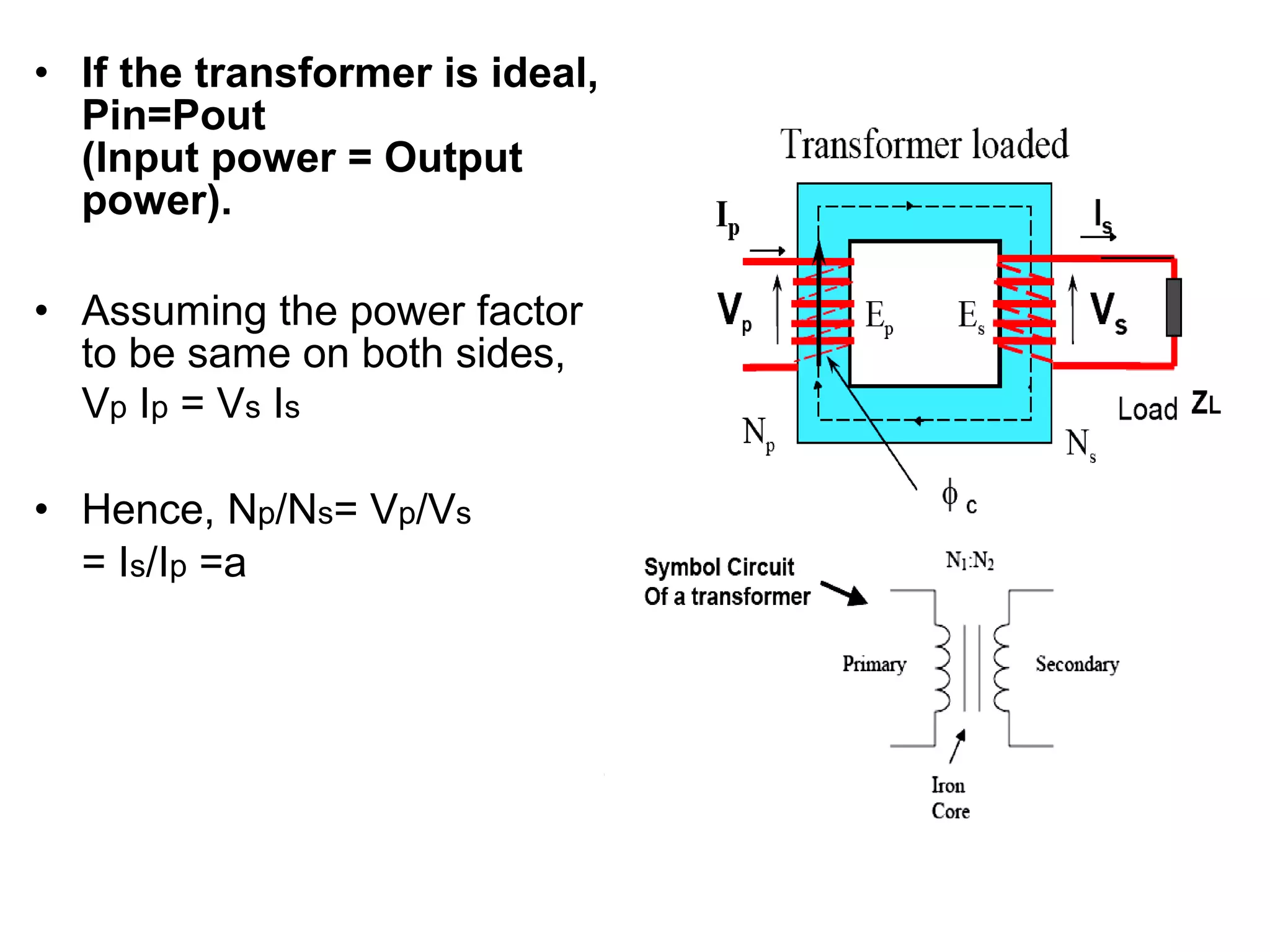
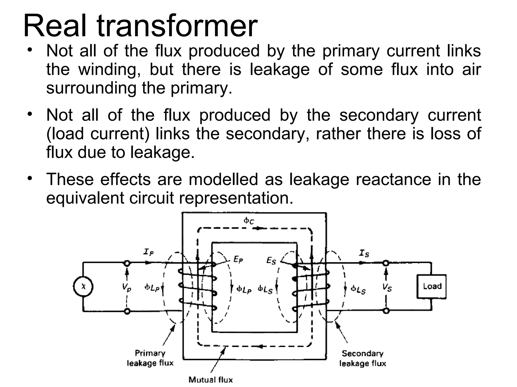
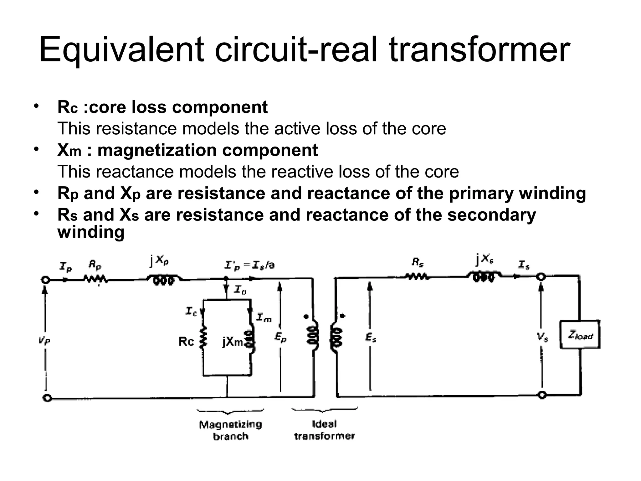
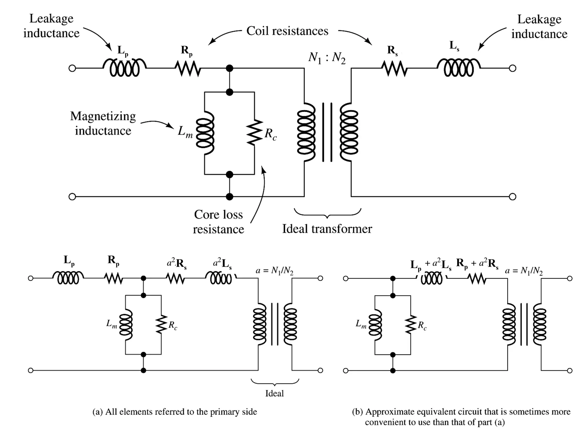
This document summarizes key concepts about transformers: 1) Transformers transfer electrical energy from one voltage level to another through magnetic coupling between primary and secondary coils. They do not directly convert electrical to mechanical energy. 2) An ideal transformer transfers power without losses, but real transformers have resistive losses in their coils and core that reduce efficiency. 3) The voltage and current ratios between primary and secondary coils are determined by their relative turn ratios; this relationship allows impedances to be transferred between sides.


