Downloaded 385 times

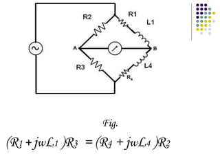
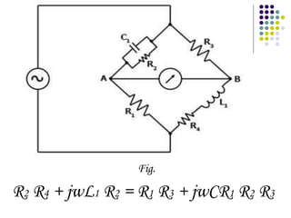
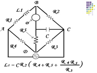


This document discusses several types of AC bridges used to measure unknown resistances, capacitances, and inductances. The Maxwell's inductance bridge uses two known impedances on one side and two pure resistances on the other to measure an unknown impedance. The Maxwell's capacitance bridge can measure unknown inductance by compensating the positive phase angle of inductance with the negative phase angle of capacitance. The Anderson bridge precisely measures unknown inductance over a wide range by using a known capacitance and resistance.


