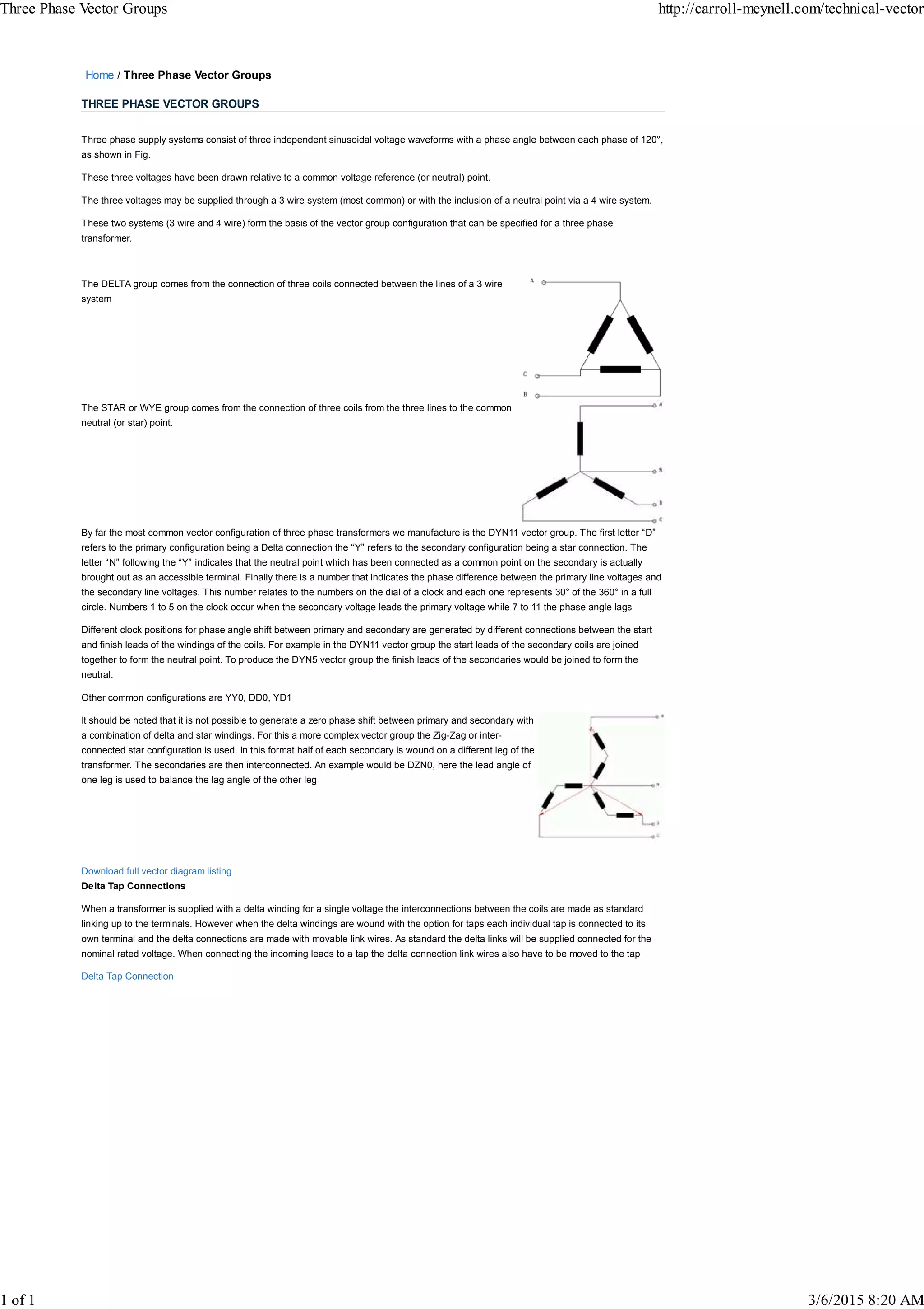
Three phase supply systems consist of three sinusoidal voltage waveforms with 120° phase differences between each phase. These voltages can be supplied via a 3-wire or 4-wire system, forming the basis for vector group configurations in three phase transformers. Common vector groups include Delta-Star (DYN11), where the primary is Delta and secondary is Star/Wye, and the number indicates the phase difference between primary and secondary voltages. Different phase differences are produced by varying the start/finish connections of the windings. More complex configurations like Zig-Zag are required to produce a zero phase shift between primary and secondary.