Downloaded 225 times
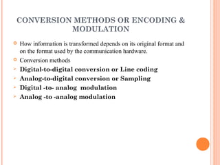
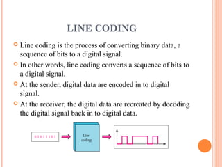
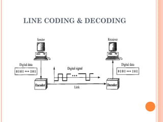


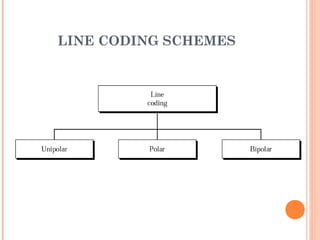
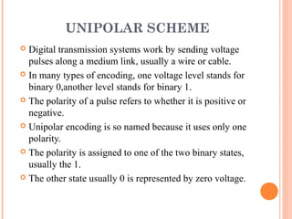


This document provides an overview of a lecture on data communications and networking. It discusses various topics related to line coding, including conversion methods, characteristics of line coding, and different line coding schemes. Specifically, it defines line coding as the process of converting binary data to a digital signal, and discusses signal level, data rate, pulse rate, DC component, and self-synchronization in the context of line coding. It also explains different line coding schemes such as unipolar, polar, NRZ, RZ, Manchester, and bipolar encoding.


![Introduction to Signal Processing Orfanidis [Solution Manual]](https://cdn.slidesharecdn.com/ss_thumbnails/51628783-solution-signal-processing-160422182740-thumbnail.jpg?width=640&height=640&fit=bounds)