Syllabus
Digital Transmission-digital-to-digital conversion
Line Coding
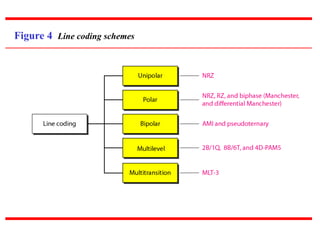
Line Coding Schemes
analog-to-digital conversion
Pulse Code Modulation (PCM)
Transmission Modes
Parallel Transmission
Serial Transmission
Analog Transmission
digital-to-analog Conversion
Aspects of Digital-to-Analog Conversion
Amplitude Shift Keying, Frequency Shift Keying, Phase
Shift Keying
analog-to-analog Conversion, Amplitude Modulation (AM),
Frequency Modulation (FM), Phase Modulation (PM)
Multiplexing, Frequency-Division Multiplexing, Wavelength-
Division Multiplexing, Time-Division Multiplexing.
3.
Syllabus cont
TransmissionMedia-Guided Media, Twisted-Pair
Cable, Coaxial Cable, Fiber-Optic Cable
Switching, Three Methods of Switching , Circuit
Switched Networks, Packet Switching
Introduction to Data-Link Layer-Nodes and Links
Services
Two Sub-layers
Three Types of addresses
Address Resolution Protocol (ARP)
Error Detection and Correction introduction
Types of Errors
Redundancy
Detection versus Correction
4.
DIGITAL-TO-DIGITAL CONVERSION
DIGITAL-TO-DIGITAL CONVERSION
Theconversion involves three techniques:
The conversion involves three techniques: line coding
line coding,
,
block coding
block coding, and
, and scrambling
scrambling.
.
Line coding is always needed; block coding and
Line coding is always needed; block coding and
scrambling may or may not be needed.
scrambling may or may not be needed.
Line Coding
Line Coding Schemes
Block Coding
Scrambling
Topics discussed in this section:
Topics discussed in this section:
5.
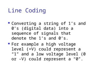
Line Coding
Convertinga string of 1’s and
0’s (digital data) into a
sequence of signals that
denote the 1’s and 0’s.
For example a high voltage
level (+V) could represent a
“1” and a low voltage level (0
or -V) could represent a “0”.
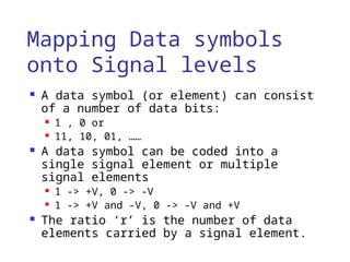
Mapping Data symbols
ontoSignal levels
A data symbol (or element) can consist
of a number of data bits:
1 , 0 or
11, 10, 01, ……
A data symbol can be coded into a
single signal element or multiple
signal elements
1 -> +V, 0 -> -V
1 -> +V and -V, 0 -> -V and +V
The ratio ‘r’ is the number of data
elements carried by a signal element.
8.
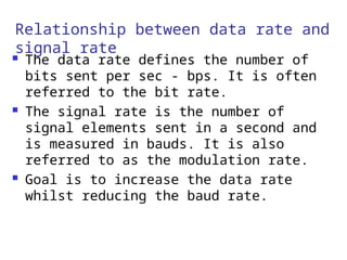
Relationship between datarate and
signal rate
The data rate defines the number of
bits sent per sec - bps. It is often
referred to the bit rate.
The signal rate is the number of
signal elements sent in a second and
is measured in bauds. It is also
referred to as the modulation rate.
Goal is to increase the data rate
whilst reducing the baud rate.
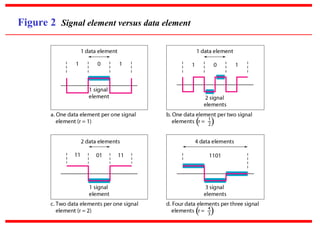
Data rate andBaud
rate
The baud or signal rate can be
expressed as:
S = c x N x 1/r bauds
S = c x N x 1/r bauds
where N is data rate
c is the case factor (worst, best
& avg.)
r is the ratio between data
element & signal element
11.
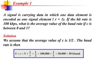
A signal iscarrying data in which one data element is
encoded as one signal element ( r = 1). If the bit rate is
100 kbps, what is the average value of the baud rate if c is
between 0 and 1?
Solution
We assume that the average value of c is 1/2 . The baud
rate is then
Example 1
12.
Although the actualbandwidth of a
digital signal is infinite, the effective
bandwidth is finite.
Note
13.
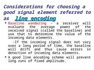
Considerations for choosinga
good signal element referred to
as line encoding
line encoding
Baseline wandering - a receiver will
evaluate the average power of the
received signal (called the baseline) and
use that to determine the value of the
incoming data elements.
-If the incoming signal does not vary
over a long period of time, the baseline
will drift and thus cause errors in
detection of incoming data elements.
A good line encoding scheme will prevent
long runs of fixed amplitude.
14.
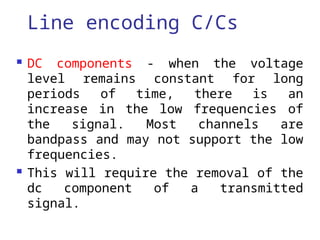
Line encoding C/Cs
DC components - when the voltage
level remains constant for long
periods of time, there is an
increase in the low frequencies of
the signal. Most channels are
bandpass and may not support the low
frequencies.
This will require the removal of the
dc component of a transmitted
signal.
15.
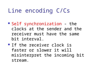
Line encoding C/Cs
Self synchronization - the
clocks at the sender and the
receiver must have the same
bit interval.
If the receiver clock is
faster or slower it will
misinterpret the incoming bit
stream.
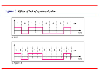
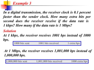
In a digitaltransmission, the receiver clock is 0.1 percent
faster than the sender clock. How many extra bits per
second does the receiver receive if the data rate is
1 kbps? How many if the data rate is 1 Mbps?
Solution
At 1 kbps, the receiver receives 1001 bps instead of 1000
bps.
Example 3
At 1 Mbps, the receiver receives 1,001,000 bps instead of
1,000,000 bps.
18.
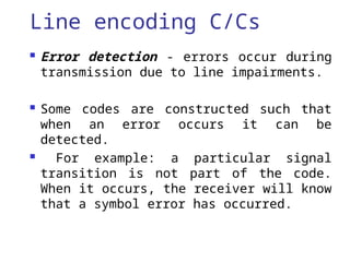
Line encoding C/Cs
Error detection - errors occur during
transmission due to line impairments.
Some codes are constructed such that
when an error occurs it can be
detected.
For example: a particular signal
transition is not part of the code.
When it occurs, the receiver will know
that a symbol error has occurred.
19.
Line encoding C/Cs
Noise and interference - there
are line encoding techniques
that make the transmitted
signal “immune” to noise and
interference.
This means that the signal
cannot be corrupted, it is
stronger than error detection.
20.
Line encoding C/Cs
Complexity - the more robust
and resilient the code, the
more complex it is to
implement and the price is
often paid in baud rate or
required bandwidth.
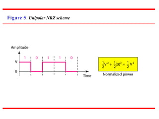
Unipolar
All signallevels are on one side
of the time axis - either above or
below
eg:-NRZ - Non Return to Zero
scheme
Scheme is prone to baseline
wandering and DC components.
-It has no synchronization or any
error detection.
-It is simple but costly in power
consumption.
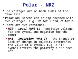
Polar - NRZ
The voltages are on both sides of the
time axis.
Polar NRZ scheme can be implemented with
two voltages. E.g. +V for 1 and -V for 0.
There are two versions:
NZR - Level (NRZ-L) - positive voltage
for one symbol and negative for the
other
NRZ - Inversion (NRZ-I) - the change or
lack of change in polarity determines
the value of a symbol. E.g. a “1”
symbol inverts the polarity a “0” does
not.
In NRZ-L thelevel of the voltage
determines the value of the bit.
In NRZ-I the inversion
or the lack of inversion
determines the value of the bit.
Note
27.
NRZ-L and NRZ-Iboth have an average
signal rate of N/2 Bd.
Note
28.
NRZ-L and NRZ-Iboth have a DC
component problem and baseline
wandering, it is worse for NRZ-L. Both
have no self synchronization &no error
detection. Both are relatively simple to
implement.
Note
29.
A system isusing NRZ-I to transfer 1-Mbps data. What
are the average signal rate and minimum bandwidth?
Solution
The average signal rate is S= c x N x R = 1/2 x N x 1 =
500 kbaud. The minimum bandwidth for this average
baud rate is Bmin = S = 500 kHz.
Note c = 1/2 for the avg. case as worst case is 1 and best
case is 0
Example 4
30.
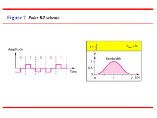
Polar - RZ
The Return to Zero (RZ) scheme uses three
voltage values. +, 0, -.
Each symbol has a transition in the middle.
Either from high to zero or from low to
zero.
This scheme has more signal transitions (two
per symbol) and therefore requires a wider
bandwidth.
No DC components or baseline wandering.
Self synchronization - transition indicates
symbol value.
More complex as it uses three voltage level.
It has no error detection capability.
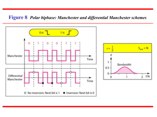
Polar - Biphase:Manchester
and Differential Manchester
Manchester coding consists of combining
the NRZ-L and RZ schemes.
Every symbol has a level transition in the
middle: from high to low or low to high.
Uses only two voltage levels.
Differential Manchester coding consists
of combining the NRZ-I and RZ schemes.
Every symbol has a level transition in the
middle. But the level at the beginning of
the symbol is determined by the symbol
value. One symbol causes a level change the
other does not.
33.
Figure 8 Polarbiphase: Manchester and differential Manchester schemes
34.
In Manchester anddifferential
Manchester encoding, the transition
at the middle of the bit is used for
synchronization.
Note
35.
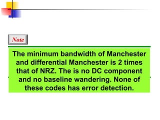
The minimum bandwidthof Manchester
and differential Manchester is 2 times
that of NRZ. The is no DC component
and no baseline wandering. None of
these codes has error detection.
Note
36.
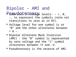
Bipolar - AMIand
Pseudoternary
Code uses 3 voltage levels: - +, 0,
-, to represent the symbols (note not
transitions to zero as in RZ).
Voltage level for one symbol is at
“0” and the other alternates between
+ & -.
Bipolar Alternate Mark Inversion
(AMI) - the “0” symbol is represented
by zero voltage and the “1” symbol
alternates between +V and -V.
Pseudoternary is the reverse of AMI.
Bipolar C/Cs
Itis a better alternative to
NRZ.
Has no DC component or baseline
wandering.
Has no self synchronization
because long runs of “0”s results
in no signal transitions.
No error detection.
39.
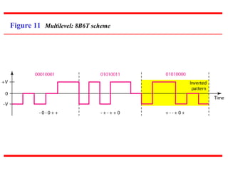
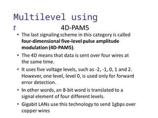
Multilevel Schemes
Inthese schemes we increase the number
of data bits per symbol thereby
increasing the bit rate.
Since we are dealing with binary data
we only have 2 types of data element a
1 or a 0.
We can combine the 2 data elements into
a pattern of “m” elements to create
“2m
” symbols.
If we have L signal levels, we can use
“n” signal elements to create Ln
signal
elements.
40.
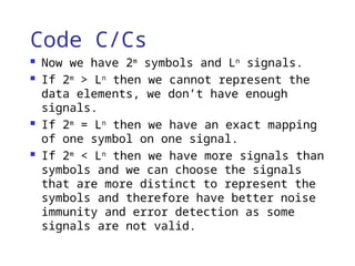
Code C/Cs
Nowwe have 2m
symbols and Ln
signals.
If 2m
> Ln
then we cannot represent the
data elements, we don’t have enough
signals.
If 2m
= Ln
then we have an exact mapping
of one symbol on one signal.
If 2m
< Ln
then we have more signals than
symbols and we can choose the signals
that are more distinct to represent the
symbols and therefore have better noise
immunity and error detection as some
signals are not valid.
41.
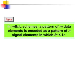
In mBnL schemes,a pattern of m data
elements is encoded as a pattern of n
signal elements in which 2m
≤ Ln
.
Note
42.
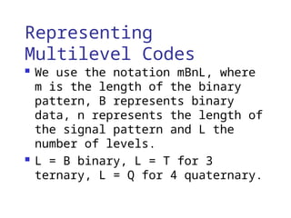
Representing
Multilevel Codes
Weuse the notation mBnL, where
m is the length of the binary
pattern, B represents binary
data, n represents the length of
the signal pattern and L the
number of levels.
L = B binary, L = T for 3
ternary, L = Q for 4 quaternary.
Redundancy
In the2B1Q scheme we have no redundancy
and we see that a DC component is present.
If we use a code with redundancy we can
decide to use only “0” or “+” weighted
codes (more +’s than -’s in the signal
element) and invert any code that would
create a DC component. E.g. ‘+00++-’ -> ‘-
00--+’
Receiver will know when it receives a “-”
weighted code that it should invert it as
it doesn’t represent any valid symbol.
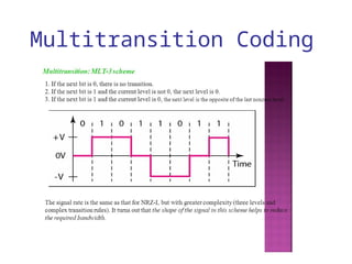
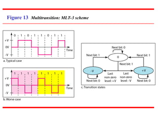
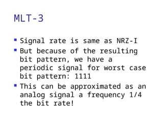
MLT-3
Signal rateis same as NRZ-I
But because of the resulting
bit pattern, we have a
periodic signal for worst case
bit pattern: 1111
This can be approximated as an
analog signal a frequency 1/4
the bit rate!
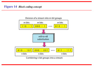
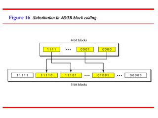
Block Coding
Fora code to be capable of error
detection, we need to add redundancy, i.e.,
extra bits to the data bits.
Synchronization also requires redundancy -
transitions are important in the signal
flow and must occur frequently.
Block coding is done in three steps:
division, substitution and combination.
It is distinguished from multilevel coding
by use of the slash - xB/yB.
The resulting bit stream prevents certain
bit combinations that when used with line
encoding would result in DC components or
poor sync. quality.
53.
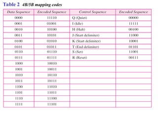
Block coding isnormally referred to as
mB/nB coding;
it replaces each m-bit group with an
n-bit group.
Note
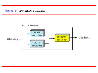
More bits -better error
detection
The 8B10B block code adds
more redundant bits and can
thereby choose code words
that would prevent a long run
of a voltage level that would
cause DC components.
60.
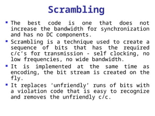
Scrambling
The bestcode is one that does not
increase the bandwidth for synchronization
and has no DC components.
Scrambling is a technique used to create a
sequence of bits that has the required
c/c’s for transmission - self clocking, no
low frequencies, no wide bandwidth.
It is implemented at the same time as
encoding, the bit stream is created on the
fly.
It replaces ‘unfriendly’ runs of bits with
a violation code that is easy to recognize
and removes the unfriendly c/c.
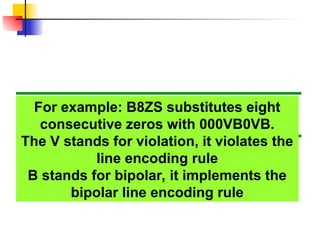
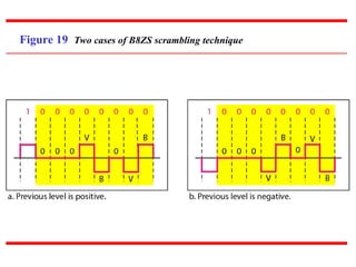
For example: B8ZSsubstitutes eight
consecutive zeros with 000VB0VB.
The V stands for violation, it violates the
line encoding rule
B stands for bipolar, it implements the
bipolar line encoding rule
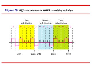
HDB3 substitutes fourconsecutive
zeros with 000V or B00V depending
on the number of nonzero pulses after
the last substitution.
If # of non zero pulses is even the
substitution is B00V to make total # of
non zero pulse even.
If # of non zero pulses is odd the
substitution is 000V to make total # of
non zero pulses even.