SlideShare a Scribd company logo
Digital Communication (GTU)                            5-1                         Pulse Code Modulation


                      Chapter    5                 :         Pulse     Code
                      Modulation


Section 5.9 :

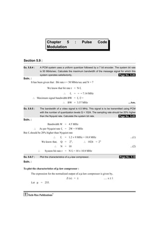
Ex. 5.9.4 :    A PCM system uses a uniform quantizer followed by a 7 bit encoder. The system bit rate
               is 50 Mbits/sec. Calculate the maximum bandwidth of the message signal for which this
               system operates satisfactorily.                                           .Page No. 5-26.
Soln. :
      It has been given that : Bit rate r = 50 Mbits/sec and N = 7

                      We know that bit rate r = N fs

                                       ∴     fs    = = = 7.14 MHz
          ∴ Maximum signal bandwidth BW = fs /2 =
                                       ∴ BW = 3.57 MHz                                           ...Ans.

Ex. 5.9.5 :    The bandwidth of a video signal is 4.5 MHz. This signal is to be transmitted using PCM
               with the number of quantization levels Q = 1024. The sampling rate should be 20% higher
               than the Nyquist rate. Calculate the system bit rate.                     .Page No. 5-26.
Soln. :
                      Bandwidth W = 4.5 MHz
          ∴ As per Nyquist rate fs = 2W = 9 MHz
But fs should be 20% higher than Nyquist rate
                            ∴     fs    = 1.2 × 9 MHz = 10.8 MHz                                   ...(1)
                  We know that,   Q =         N
                                             2 ,             ∴ 1024 = 2N


                            ∴     N = 10                                                           ...(2)
              ∴     System bit rate r = N fs = 10 × 10.8 MHz

Ex. 5.9.7 :    Plot the characteristics of a µ-law compressor.                            .Page No. 5-30
Soln. :

To plot the characteristics of µ-law compressor :
       The expression for the normalized output of a µ-law compressor is given by,
                                           Z (x) = ±                       ..... x ≤ 1
       Let µ = 255.
Digital Communication (GTU)                         5-2                            Pulse Code Modulation

       Note that instead of |x| / xmax we have written only |x| and restricted the values of x only upto 1.
This has the same effect as that of normalizing.
                                      ∴ Z (x) = ±                                                     ...(1)
      Substitute x = 0, 0.2, 0.4, 0.6, 0.8 and 1 in Equation (1) to get the corresponding values of Z as
shown in the following table.
                            |x|   0      0.2      0.4     0.6      0.8     1
                             Z    0       ±       ±        ±       ±      ±1
                                         0.71    0.84     0.9     0.96
       Therefore the compressor characteristics is as shown in Fig. P. 5.9.7.


                            Fig. P. 5.9.7 : µ-law compressor characteristics

Section 5.15 :

Ex. 5.15.7 :   If a voice frequency signal is sampled at the rate of 32,000 samples/sec and
               characterized by peak value of 2 Volts, determine the value of step size to avoid slope
               overload. What is quantization noise power Nq and corresponding SNR ? Assume
               bandwidth of signal as 4 kHz.                                           .Page No. 5-60.
Soln. :
Given :    fs = 32,000 samples/sec.
           Peak value of the signal A = 2V.
           Bandwidth B = 4 kHz.
1.    Step size δ to avoid slope overload :
      To avoid slope overload the following condition should be satisfied.
                                               A ≤ =
       Substituting the values we get,
Digital Communication (GTU)                          5-3                           Pulse Code Modulation

                                          2 ≤
                                  ∴       δ ≥
                                  ∴       δ ≥ 1.57 Volt                                            ...Ans.
2.    Quantization noise power (Nq) :
      The quantization noise power for a delta modulator is given by,
                                         Nq = =
                                   ∴ Nq = 0.822 W                                                  ...Ans.
3.    Signal to noise ratio :
                                      SNR = = = 19.45
Ex. 5.15.8 :   A compact disc (CD) records audio signals digitally by PCM. Assume audio signal's
               bandwidth to be 15 kHz. If signals are sampled at a rate 20% above Nyquist rate for
               practical reasons and the samples are quantised into 65,536 levels, determine bits/sec
               required to encode the signal and minimum bandwidth required to transmit encoded
               signal.                                                                .Page No. 5-60
Soln. :
           W = 15 kHz,
           fs = 1.2 × 2 W = 2.4 × 15 kHz = 36 kHz,
           Q = 65,536.
1.    Signaling rate (r) :
                            We know that Q =        2N
                                      ∴ N =         log2 Q
                                      ∴ N =                         = 16                              ...(1)
                             Signaling rate r =     N fs = 16 × 36 kHz = 576 kbits/sec.            ...Ans.
      Thus the signaling rate r is 576 kbits/sec.
2.    Minimum bandwidth :
                                           BT =
                               Signaling rate =      kbits/sec
               ∴ Minimum bandwidth BT =             288 kHz                                        ...Ans.
Ex. 5.15.9 :   In a single integration DM scheme, the voice signal is sampled at a rate of 64 kHz. The
               maximum signal amplitude is 1 Volt.
               1.   Determine the minimum value of step size to avoid slope overload.
               2.   Determine granular noise power N0, if the voice signal bandwidth is 3.5 kHz.
               3.   Assuming signal to be sinusoidal, calculate signal power So and signal to noise
                    ratio (SNR).
               4.   Assuming that the voice signal amplitude is uniformly distributed in the range,
                    (– 1, 1), determine So and SNR.                                  .Page No. 5-60
Soln. :
Given : fs = 64 kHz    A = 1 Volt
1.    Minimum step size to avoid slope overload :
                                        A ≤ ,
Digital Communication (GTU)                          5-4                           Pulse Code Modulation

                                       ∴ δmin = = = 0.3436 Volt...Ans.
2.      Granular noise power :
                                             Nq = × = × = 2.15 × 10– 3 W                          ...Ans.
3.      Signal power So and SNRo :
        As the signal is sinusoidal, the normalized output signal power
                                             So = [A/]2 = A/2 = 1/2 Watt. ...Ans.
                                      ∴ SNRo = = = 232.3 or 23.66 dB.
4.      Signal power for uniformly distributed signal :
        The signal PDF for a uniformly distributed signal is as shown in Fig. P. 5.15.9.


                                               Fig. P. 5.15.9

     ∴ Mean square value of the signal, E[S2] = S2 ⋅ fs (S) dS = S2 dS = = 1/3
       Assuming R = 1.
                Normalized signal power So = Mean square value = 1/3 W                            ...Ans.
                Signal to noise ratio = SNR = = 155.03 or 21.9 dB ...Ans.

Ex. 5.15.10 :   The information in an analog signal voltage waveform is to be transmitted over a PCM
                system with an accuracy of ± 0.1 % full scale accuracy. The analog voltage waveform has
                a bandwidth of 100 Hz and an amplitude range of – 10 to + 10 Volts.
                (a)   Determine the minimum sampling rate required.
                (b)   Determine the number of bits in each PCM word.
                (c)   Determine the minimum bit rate required in the PCM system.
                (d)   Determine the minimum absolute channel bandwidth required for the transmission
                      of the PCM signal.                                                   .Page No. 5-61
Soln. :
      It has been given that,
1.    Accuracy of ± 0.1 % of full scale is expected.
2.    W = 100 Hz and amplitude range is – 10 to + 10 V
(a)     Sampling rate fs :
        By sampling theorem the minimum sampling rate is
                                           fs (min) = 2W = 200 Hz                                 ...Ans.
(b)     Number of bits per word (N) :
       As accuracy is expected to be ± 0.1 % of full scale, the maximum quantization error should be
± 0.1 % of full scale.
Digital Communication (GTU)                        5-5                           Pulse Code Modulation


                                  ∴       ∈max = ± 0.1 % of full scale
                                               = ± 0.001 [10 – (– 10)] = ± 0.001 × 20
                                  ∴       ∈max = ± 0.02 Volts                                    ...(1)
      We know that the maximum value of the quantization error is
                                          ∈max = ± S/2                                           ...(2)
                                  ∴ ± S/2 = ± 0.02
                                  ∴         S = 0.04 Volt                                        ...(3)
                                        But S =
                                where      VH = 10 V
                                  and      VL = – 10 V
                                    ∴       Q =
                                               = = 500                                           ...(4)
                                      But Q = 2N
                               ∴ N log10 2 = log10 500
                                      ∴     N = 8.96 ≈ 9                                       ...Ans.
(c)   System bit rate :

                          System bit rate (r) = N fs = 9 × 200 = 1800 bits/sec                 ...Ans.
Digital Communication (GTU)                              5-6                      Pulse Code Modulation


(d)   Transmission channel bandwidth (BT) :

                                                 BT ≥ N fs
                                           ∴ BT ≥ 900 Hz                                           ...Ans.
Ex. 5.15.11 :   The information in an analog waveform with a maximum frequency fm = 3 kHz is to be
                transmitted over an M level PCM system, where the number of pulse levels is M = 16.
                The quantization distortion is specified not to exceed 1% of peak to peak analog signal.
                1.    What is the maximum number of bits per sample that should be used in this
                      PCM system ?
                2.    What is the minimum sampling rate and what is the resulting bit transmission rate ?
                                                                                          .Page No. 5-61
Soln. :
Given : fm = 3 kHz,
      Number of quantization levels M = 16.
1.    Number of bits/sample (N) :
      We know that, number of quantization levels M = 2N.
                                           ∴     2N = 16
                                       ∴          N = 4                                            ...Ans.
2.    Minimum sampling rate :
          By sampling theorem :                fs (min) = 2 fm = 2 × 3 kHz
                                       ∴       fs (min) = 6 kHz                                    ...Ans.
3.    Bit transmission rate :
                                                   r = N fs = 4 × 6 kHz
                                           ∴       r = 24 kbits/sec.                               ...Ans.
      ∴    Number of quantization levels, Q = 2 = 2 = 128N     7
                                                                                                   ...Ans.
Ex. 5.15.12 :   A TV signal with a bandwidth of 4.2 MHz is transmitted using binary PCM. The number of
                quantization levels is 512. Calculate :
                1.    Code word length
                2.    Transmission bandwidth
                3.    Final bit rate
                4.    Output signal to quantization noise ratio.                          .Page No. 5-61
Soln. :
Given :   fm = 4.2 MHz and Q = 512.
1.    Code word length (N) :
                                                  Q = 2N
                                           ∴      N =
                                           ∴      N = 9 bits/word                                  ...Ans.
2.    Transmission bandwidth :
Digital Communication (GTU)                          5-7                          Pulse Code Modulation


                                             BT = N fs = N (2 fm)
                                       ∴ BT = 9 × 4.2 MHz = 37.8 MHz                               ...Ans.
3.    Final bit rate (r) :
                                              r = N fs = 9 × 2 × fm = 18 × 4.2 MHz
                                         ∴    r = 75.6 Mb/s                                        ...Ans.
4.     Signal to quantization noise ratio :
       Since the TV signal is not a sinusoidal signal, let us use the general expression of signal to
quantization noise ratio.
                                                = 4.8 + 6 N dB = 4.8 + (6 × 9)
                                          ∴     = 58.8 dB                                          ...Ans.
      This is the maximum signal to noise ratio that we are expected to get from this system.

Ex. 5.15.13 :   The output signal to noise ratio (SNR) of a 10 bit PCM was found to be 30 dB. The
                desired SNR is 42 dB. It was decided to increase the SNR to the desired value by
                increasing the number of quantization levels. Find fractional increase in the transmission
                bandwidth required for this SNR.                                          .Page No. 5-61
Soln. :
Given :     SNR = 30 dB, N = 10
            Desired value of SNR = 42 dB.
1.    To find “N” for SNR = 42 dB
      With increase in N by 1 bit the value of SNR increases by 6 dB. Therefore to increase the value
of SNR by 12 dB it is necessary to increase N by 2.
                                        ∴ N = 10 + 2 = 12                                          ...Ans.
2.    Fractional increase in BW :

                      BW of PCM system =         N fs
                             ∴ BW with N = 10 is given by, BW10 = × 10 fs = 5 fs
                             and BW with N = 12 is given by, BW12= × 12 fs = 6 fs
                       ∴     Change in BW = ∆ BW = 6 fs – 5 fs = fs
            ∴    Fractional change in BW =         = × 100 % = 20 %...Ans.

Ex. 5.15.14 :   A telephone signal with cut-off frequency of 4 kHz is digitised into 8 bit PCM, sampled at
                Nyquist rate. Calculate the baseband transmission bandwidth and quantization S/N ratio.
                                                                                          .Page No. 5-61
Soln. :

1.                 The Nyquist rate    = 2 × 4 kHz = 8 kHz.
Digital Communication (GTU)                           5-8                             Pulse Code Modulation


2.    Transmission bandwidth, BT          =   ⋅ N fs = × 8 × 8 kHz = 32 kHz                         ...Ans.

3.                             SNRq       = (1.8 + 6N) dB = 1.8 + (6 × 8) = 49.8 dB                 ...Ans.

Ex. 5.15.15 :   In a single integration DM scheme the voice signal is sampled at a rate of 64 kHz. The
                maximum signal amplitude is 2 Volts. Voice signal bandwidth is 3.5 kHz. Determine the
                minimum value of step size to avoid slope overload and granular noise power.
                                                                                             .Page No. 5-61
Soln. :
Given :     fs = 64 kHz,     Amax = 2V,       fm = 3.5 kHz
1.    Minimum step size to avoid slope overload :
      We know that

                             Amax =

                         ∴    δmin =      = = 0.6872 Volt        ...Ans.
2.    Granular noise power :

                                              Nq = × = × = 8.6 × 10– 3 W ...Ans.

Ex. 5.15.16 :   A television signal (video and audio) has a bandwidth of 4.5 MHz. This signal is sampled,
                quantized and binary coded to obtain a PCM signal.
                1.   Determine the sampling rate if the signal is to be sampled at a rate 20% above the
                     Nyquist rate.
                2.   If the samples are quantized into 1024 levels, determine the number of binary
                pulses
                     required to encode each sample.
                3.   Determine the binary pulse rate (bits per second) of binary coded signal and the
                     minimum bandwidth required to transmit the signal.
                If above linear PCM system is converted to companded PCM, will the output bit rate
                changed ? Justify.                                                           .Page No. 5-62
Digital Communication (GTU)                            5-9                             Pulse Code Modulation


Soln. :
Given :                                        W = 4.5 MHz
1.                                Sampling rate = 1.2 × Nyquist rate = 1.2 × 2 W
                                                    = 1.2 × 2 × 4.5 × 106 = 10.8 MHz                  ...Ans.
2.       Given that number of quantization levels, Q = 1024
                                            But Q = 2N
     ∴    Number of binary pulse per word, N = log2 Q
                                         ∴       N = log2 1024
                                         ∴       N = 10                                               ...Ans.
3.                   Binary pulse rate (bit rate)   = N fs = 10 × 10.8 MHz = 108 Mbps                 ...Ans.
                                      Bandwidth =       bit rate = 54 MHz                             ...Ans.

Ex. 5.15.17 :   A compact disc (CD) records audio signals digitally by using PCM. Assume the audio
                signal bandwidth to be 15 kHz.
                1.      What is Nyquist rate ?
                2.      If the Nyquist samples are quantized into L = 65,536 levels and then binary
                        coded,determine the number of binary digits required to encode a sample.
                3.      Determine the number of binary digits per second (bit/s) required to encode
                        the audio signal.
                4.      For practical reasons, the signals are sampled at a rate well above Nyquist rate
                        at 44,100 samples per second. If L = 65,536, determine number of bits per second
                        required to encode the signal and transmission bandwidth of encoded signal.
                                                                                             .Page No. 5-62.
Soln. :
Given :   W = 15 kHz
1.    Nyquist rate = 2 W = 2 × 15 kHz = 30 kHz.                                              ...Ans.
2.    Number of quantization levels Q = 65,536
                            we know that Q = 2N
                                     ∴ 2N = 65,536
                                     ∴ N = 16 bits.                                          ...Ans.
∴ Number of bits to encode each sample is N = 16.
3.    Number of bits per second               = Number of samples/sec. × Number of bits/sample
                                              = 15 × 103 × 16 = 240 k bits/sec.             ...Ans.
4.                 Practical sampling rate fs = 44.1 kHz
            ∴ Number of bits per second = 44.1 × 16 × 103 = 705.6k bits/sec.
           ∴ Transmission bandwidth B = = = 352.8 kHz. ...Ans.
Digital Communication (GTU)                        5-10                          Pulse Code Modulation

Ex. 5.15.18 :   A Delta Modulator system operates at 3 times Nyquist rate for signal with 3.3 kHz
                bandwidth. The quantisation step is 250 mV. Determine the maximum amplitude of a 1
                kHz input sinusoid for which the DM does not show slope overload.        .Page No. 5-62.
Soln. :
Given :    W = 3.3 kHz, fm = 1 kHz, δ = 250 mV, fs = 3 × 2W = 19.8 kHz.
1.    Let the maximum amplitude of 1 kHz input sinusoid be “A”.
      The condition to avoid the slope overload is
                                             A ≤
                     ∴ Maximum value of A = =
                Substituting the values we get,
                                          Amax =
                                      ∴ Amax = 0.787

Ex. 5.15.19 :   An audio signal with highest frequency component 3300 Hz is pulse code modulated with
                a sampling rate of 8000 samples/sec. The required signal-to-quantisation noise ratio is
                40 dB.
                1.    What is the minimum number of uniform quantising levels needed ?
                2.    What is the minimum number of bits per sample needed ?
                3.    Calculate the minimum number of bits per sample needed ?           .Page No. 5-62.
Soln. :
Given : fs = 8000 samples/sec. , fm = 3300 Hz.     = 40 dB
1.    To calculate Q and N :
      Assuming the input signal to be non sinusoidal we write
                                        S/N = (4.8 + 6 N) dB
                                    ∴ 40 = 4.8 + 6N
                                    ∴     N = 5.86 ≈ 6                                           ...Ans.
      Thus the number of bits per word is 6.
                                          Q = 2N = 26 = 64                                       ...Ans.
      Thus the number of quantization level is 64.
2.    The signaling rate (r) :

                                              r = N fs = 6 × 8 × 103 = 48 kbits/sec.
3.    Transmission bandwidth :

                         Minimum BW,        BT = r = 24 kHz.

Ex. 5.15.20 :   Delta modulator (DM) gives output pulses + p (t) of – p (t). The output of DM is + p (t)
                when instantaneous sample is larger than previous sample value and is – p(t) when
                instantaneous sample is smaller than previous sample value (last sample). The p(t) has
                2 microsecond duration and 628 mV amplitude and repeats every 10 microsecond. Plot
Digital Communication (GTU)                        5-11                         Pulse Code Modulation

                the input and output of DM on graph paper one below other to same scale if the input to
                DM is 1 Volt sine wave of frequency 10 kHz for one cycle of input wave. What is the
                maximum frequency with 1 Volt amplitude that can be used in this system without slope
                overload distortion.                                                   .Page No. 5-62.
Soln.
Part I : To plot the DM signal
        The D. M. Signal is as shown in Fig. P. 5.15.20.


                                       Fig. P. 5.15.20 : DM signal

Part II : Maximum frequency :
Given :
        A = 1V, fm = 10 kHz,
             fs = 1/Ts = 1/10 µ s = 100 kHz. δ = 265 mV.
        The condition for avoiding the slope overload is

                                            A >

                                        ∴ 1 =

                                       ∴   ωn = 25.6 × 10³ rad /sec.
Digital Communication (GTU)                     5-12                          Pulse Code Modulation


                                   ∴    fmax = 4074.36 Hz                                      ...Ans.

      This is the maximum input frequency without introducing any slope overload distortion.

                                                                                               

More Related Content

What's hot

Frequency-Shift Keying
Frequency-Shift KeyingFrequency-Shift Keying
Frequency-Shift Keying
Jessie Rama
 
Amplitude shift keying
Amplitude shift keyingAmplitude shift keying
Amplitude shift keying
Sunny Kumar
 
NYQUIST CRITERION FOR ZERO ISI
NYQUIST CRITERION FOR ZERO ISINYQUIST CRITERION FOR ZERO ISI
NYQUIST CRITERION FOR ZERO ISI
FAIZAN SHAFI
 
Pulse Modulation ppt
Pulse Modulation pptPulse Modulation ppt
Pulse Modulation ppt
sanjeev2419
 
Simulating communication systems with MATLAB: An introduction
Simulating communication systems with MATLAB: An introductionSimulating communication systems with MATLAB: An introduction
Simulating communication systems with MATLAB: An introduction
Aniruddha Chandra
 
Comparsion of M-Ary psk,fsk,qapsk.pptx
Comparsion of M-Ary psk,fsk,qapsk.pptxComparsion of M-Ary psk,fsk,qapsk.pptx
Comparsion of M-Ary psk,fsk,qapsk.pptx
keshav11845
 
Sampling Theorem
Sampling TheoremSampling Theorem
Sampling Theorem
Dr Naim R Kidwai
 
Decimation and Interpolation
Decimation and InterpolationDecimation and Interpolation
Decimation and Interpolation
Fernando Ojeda
 
Solved problems in waveguides
Solved problems in waveguidesSolved problems in waveguides
Solved problems in waveguides
subhashinivec
 
M ary psk modulation
M ary psk modulationM ary psk modulation
M ary psk modulation
Ahmed Diaa
 
Modulation of LED
Modulation of LEDModulation of LED
Modulation of LED
Priyanka Anni
 
FM demodulation using PLL
FM demodulation using PLLFM demodulation using PLL
FM demodulation using PLL
mpsrekha83
 
Overlap Add, Overlap Save(digital signal processing)
Overlap Add, Overlap Save(digital signal processing)Overlap Add, Overlap Save(digital signal processing)
Overlap Add, Overlap Save(digital signal processing)
Gourab Ghosh
 
Transmission line, single and double matching
Transmission line, single and double matchingTransmission line, single and double matching
Transmission line, single and double matching
Shankar Gangaju
 
Pulse shaping
Pulse shapingPulse shaping
Pulse shaping
Ramraj Choudhary
 
Line coding
Line coding Line coding
Line coding
Ravindra Rathore
 
Coherent and Non-coherent detection of ASK, FSK AND QASK
Coherent and Non-coherent detection of ASK, FSK AND QASKCoherent and Non-coherent detection of ASK, FSK AND QASK
Coherent and Non-coherent detection of ASK, FSK AND QASK
naimish12
 
Communication Engineering - Chapter 6 - Noise
Communication Engineering - Chapter 6 - NoiseCommunication Engineering - Chapter 6 - Noise
Communication Engineering - Chapter 6 - Noisemkazree
 

What's hot (20)

Frequency-Shift Keying
Frequency-Shift KeyingFrequency-Shift Keying
Frequency-Shift Keying
 
Amplitude shift keying
Amplitude shift keyingAmplitude shift keying
Amplitude shift keying
 
NYQUIST CRITERION FOR ZERO ISI
NYQUIST CRITERION FOR ZERO ISINYQUIST CRITERION FOR ZERO ISI
NYQUIST CRITERION FOR ZERO ISI
 
Pulse Modulation ppt
Pulse Modulation pptPulse Modulation ppt
Pulse Modulation ppt
 
Simulating communication systems with MATLAB: An introduction
Simulating communication systems with MATLAB: An introductionSimulating communication systems with MATLAB: An introduction
Simulating communication systems with MATLAB: An introduction
 
Comparsion of M-Ary psk,fsk,qapsk.pptx
Comparsion of M-Ary psk,fsk,qapsk.pptxComparsion of M-Ary psk,fsk,qapsk.pptx
Comparsion of M-Ary psk,fsk,qapsk.pptx
 
Sampling Theorem
Sampling TheoremSampling Theorem
Sampling Theorem
 
Decimation and Interpolation
Decimation and InterpolationDecimation and Interpolation
Decimation and Interpolation
 
Solved problems in waveguides
Solved problems in waveguidesSolved problems in waveguides
Solved problems in waveguides
 
M ary psk modulation
M ary psk modulationM ary psk modulation
M ary psk modulation
 
Modulation of LED
Modulation of LEDModulation of LED
Modulation of LED
 
FM demodulation using PLL
FM demodulation using PLLFM demodulation using PLL
FM demodulation using PLL
 
Overlap Add, Overlap Save(digital signal processing)
Overlap Add, Overlap Save(digital signal processing)Overlap Add, Overlap Save(digital signal processing)
Overlap Add, Overlap Save(digital signal processing)
 
Transmission line, single and double matching
Transmission line, single and double matchingTransmission line, single and double matching
Transmission line, single and double matching
 
Pulse shaping
Pulse shapingPulse shaping
Pulse shaping
 
Line coding
Line coding Line coding
Line coding
 
DSP Processor
DSP Processor DSP Processor
DSP Processor
 
Coherent and Non-coherent detection of ASK, FSK AND QASK
Coherent and Non-coherent detection of ASK, FSK AND QASKCoherent and Non-coherent detection of ASK, FSK AND QASK
Coherent and Non-coherent detection of ASK, FSK AND QASK
 
ASk,FSK,PSK
ASk,FSK,PSKASk,FSK,PSK
ASk,FSK,PSK
 
Communication Engineering - Chapter 6 - Noise
Communication Engineering - Chapter 6 - NoiseCommunication Engineering - Chapter 6 - Noise
Communication Engineering - Chapter 6 - Noise
 

Viewers also liked

Chapter 6
Chapter 6Chapter 6
Chapter 6
Faisal Mehmood
 
Line coding
Line codingLine coding
Line coding
Gagan Randhawa
 
Chapter 3 - Data and Signals
Chapter 3 - Data and SignalsChapter 3 - Data and Signals
Chapter 3 - Data and Signals
Wayne Jones Jnr
 
Chapter 4 - Digital Transmission
Chapter 4 - Digital TransmissionChapter 4 - Digital Transmission
Chapter 4 - Digital Transmission
Wayne Jones Jnr
 

Viewers also liked (8)

Chap 3
Chap 3Chap 3
Chap 3
 
Solved problems
Solved problemsSolved problems
Solved problems
 
Chap 4
Chap 4Chap 4
Chap 4
 
Chap 6
Chap 6Chap 6
Chap 6
 
Chapter 6
Chapter 6Chapter 6
Chapter 6
 
Line coding
Line codingLine coding
Line coding
 
Chapter 3 - Data and Signals
Chapter 3 - Data and SignalsChapter 3 - Data and Signals
Chapter 3 - Data and Signals
 
Chapter 4 - Digital Transmission
Chapter 4 - Digital TransmissionChapter 4 - Digital Transmission
Chapter 4 - Digital Transmission
 

Similar to Chap 5

Te 4 pulse_modulation
Te 4 pulse_modulationTe 4 pulse_modulation
Te 4 pulse_modulation
Shohan Ean
 
Chapter5DigitalPulseModulation-PulseCodeModulationPCMpart1.pptx.pptx
Chapter5DigitalPulseModulation-PulseCodeModulationPCMpart1.pptx.pptxChapter5DigitalPulseModulation-PulseCodeModulationPCMpart1.pptx.pptx
Chapter5DigitalPulseModulation-PulseCodeModulationPCMpart1.pptx.pptx
udithaisur
 
UNIT5_1.pdf
UNIT5_1.pdfUNIT5_1.pdf
UNIT5_1.pdf
ssuser6c1abb
 
Lecture_ch6.pptx
Lecture_ch6.pptxLecture_ch6.pptx
Lecture_ch6.pptx
rshoukatimtek
 
TeleCom Lecture 07.ppt
TeleCom Lecture 07.pptTeleCom Lecture 07.ppt
TeleCom Lecture 07.ppt
RiyaBatool
 
Software-defined white-space cognitive systems: implementation of the spectru...
Software-defined white-space cognitive systems: implementation of the spectru...Software-defined white-space cognitive systems: implementation of the spectru...
Software-defined white-space cognitive systems: implementation of the spectru...
CSP Scarl
 
Physical Layer Numericals - Data Communication & Networking
Physical Layer  Numericals - Data Communication & NetworkingPhysical Layer  Numericals - Data Communication & Networking
Physical Layer Numericals - Data Communication & Networking
Drishti Bhalla
 
Modulation technology
Modulation technologyModulation technology
Modulation technology
Pei-Che Chang
 
Multiband Transceivers - [Chapter 4] Design Parameters of Wireless Radios
Multiband Transceivers - [Chapter 4] Design Parameters of Wireless RadiosMultiband Transceivers - [Chapter 4] Design Parameters of Wireless Radios
Multiband Transceivers - [Chapter 4] Design Parameters of Wireless Radios
Simen Li
 
Ch4 1 Data communication and networking by neha g. kurale
Ch4 1 Data communication and networking by neha g. kuraleCh4 1 Data communication and networking by neha g. kurale
Ch4 1 Data communication and networking by neha g. kurale
Neha Kurale
 
Lecture3 signal encoding_in_wireless
Lecture3  signal encoding_in_wirelessLecture3  signal encoding_in_wireless
Lecture3 signal encoding_in_wirelessYahya Alzidi
 
L 1 5 sampling quantizing encoding pcm
L 1 5 sampling quantizing encoding pcmL 1 5 sampling quantizing encoding pcm
L 1 5 sampling quantizing encoding pcm
DEEPIKA KAMBOJ
 
Unit 3.pptx
Unit 3.pptxUnit 3.pptx
Synchronous Time / Frequency Domain Measurements Using a Digital Oscilloscope...
Synchronous Time / Frequency Domain Measurements Using a Digital Oscilloscope...Synchronous Time / Frequency Domain Measurements Using a Digital Oscilloscope...
Synchronous Time / Frequency Domain Measurements Using a Digital Oscilloscope...
Rohde & Schwarz North America
 
Introduction to Channel Capacity | DCNIT-LDTalks-1
Introduction to Channel Capacity | DCNIT-LDTalks-1Introduction to Channel Capacity | DCNIT-LDTalks-1
Introduction to Channel Capacity | DCNIT-LDTalks-1
Arunabha Saha
 
blake sample-problems
blake sample-problemsblake sample-problems
blake sample-problems
John Joel Martinez
 
_Pulse-Modulation-Techniqnes.pdf
_Pulse-Modulation-Techniqnes.pdf_Pulse-Modulation-Techniqnes.pdf
_Pulse-Modulation-Techniqnes.pdf
SoyallRobi
 

Similar to Chap 5 (20)

Te 4 pulse_modulation
Te 4 pulse_modulationTe 4 pulse_modulation
Te 4 pulse_modulation
 
Analog to-digital conversion
Analog to-digital conversionAnalog to-digital conversion
Analog to-digital conversion
 
Chapter5DigitalPulseModulation-PulseCodeModulationPCMpart1.pptx.pptx
Chapter5DigitalPulseModulation-PulseCodeModulationPCMpart1.pptx.pptxChapter5DigitalPulseModulation-PulseCodeModulationPCMpart1.pptx.pptx
Chapter5DigitalPulseModulation-PulseCodeModulationPCMpart1.pptx.pptx
 
UNIT5_1.pdf
UNIT5_1.pdfUNIT5_1.pdf
UNIT5_1.pdf
 
Lecture_ch6.pptx
Lecture_ch6.pptxLecture_ch6.pptx
Lecture_ch6.pptx
 
TeleCom Lecture 07.ppt
TeleCom Lecture 07.pptTeleCom Lecture 07.ppt
TeleCom Lecture 07.ppt
 
Software-defined white-space cognitive systems: implementation of the spectru...
Software-defined white-space cognitive systems: implementation of the spectru...Software-defined white-space cognitive systems: implementation of the spectru...
Software-defined white-space cognitive systems: implementation of the spectru...
 
Physical Layer Numericals - Data Communication & Networking
Physical Layer  Numericals - Data Communication & NetworkingPhysical Layer  Numericals - Data Communication & Networking
Physical Layer Numericals - Data Communication & Networking
 
Modulation technology
Modulation technologyModulation technology
Modulation technology
 
Multiband Transceivers - [Chapter 4] Design Parameters of Wireless Radios
Multiband Transceivers - [Chapter 4] Design Parameters of Wireless RadiosMultiband Transceivers - [Chapter 4] Design Parameters of Wireless Radios
Multiband Transceivers - [Chapter 4] Design Parameters of Wireless Radios
 
Ch4 1 Data communication and networking by neha g. kurale
Ch4 1 Data communication and networking by neha g. kuraleCh4 1 Data communication and networking by neha g. kurale
Ch4 1 Data communication and networking by neha g. kurale
 
Lecture3 signal encoding_in_wireless
Lecture3  signal encoding_in_wirelessLecture3  signal encoding_in_wireless
Lecture3 signal encoding_in_wireless
 
Pulse code mod
Pulse code modPulse code mod
Pulse code mod
 
L 1 5 sampling quantizing encoding pcm
L 1 5 sampling quantizing encoding pcmL 1 5 sampling quantizing encoding pcm
L 1 5 sampling quantizing encoding pcm
 
Analog_to_Digital.pdf
Analog_to_Digital.pdfAnalog_to_Digital.pdf
Analog_to_Digital.pdf
 
Unit 3.pptx
Unit 3.pptxUnit 3.pptx
Unit 3.pptx
 
Synchronous Time / Frequency Domain Measurements Using a Digital Oscilloscope...
Synchronous Time / Frequency Domain Measurements Using a Digital Oscilloscope...Synchronous Time / Frequency Domain Measurements Using a Digital Oscilloscope...
Synchronous Time / Frequency Domain Measurements Using a Digital Oscilloscope...
 
Introduction to Channel Capacity | DCNIT-LDTalks-1
Introduction to Channel Capacity | DCNIT-LDTalks-1Introduction to Channel Capacity | DCNIT-LDTalks-1
Introduction to Channel Capacity | DCNIT-LDTalks-1
 
blake sample-problems
blake sample-problemsblake sample-problems
blake sample-problems
 
_Pulse-Modulation-Techniqnes.pdf
_Pulse-Modulation-Techniqnes.pdf_Pulse-Modulation-Techniqnes.pdf
_Pulse-Modulation-Techniqnes.pdf
 

Recently uploaded

Ethnobotany and Ethnopharmacology ......
Ethnobotany and Ethnopharmacology ......Ethnobotany and Ethnopharmacology ......
Ethnobotany and Ethnopharmacology ......
Ashokrao Mane college of Pharmacy Peth-Vadgaon
 
CLASS 11 CBSE B.St Project AIDS TO TRADE - INSURANCE
CLASS 11 CBSE B.St Project AIDS TO TRADE - INSURANCECLASS 11 CBSE B.St Project AIDS TO TRADE - INSURANCE
CLASS 11 CBSE B.St Project AIDS TO TRADE - INSURANCE
BhavyaRajput3
 
The geography of Taylor Swift - some ideas
The geography of Taylor Swift - some ideasThe geography of Taylor Swift - some ideas
The geography of Taylor Swift - some ideas
GeoBlogs
 
Model Attribute Check Company Auto Property
Model Attribute  Check Company Auto PropertyModel Attribute  Check Company Auto Property
Model Attribute Check Company Auto Property
Celine George
 
Supporting (UKRI) OA monographs at Salford.pptx
Supporting (UKRI) OA monographs at Salford.pptxSupporting (UKRI) OA monographs at Salford.pptx
Supporting (UKRI) OA monographs at Salford.pptx
Jisc
 
How to Break the cycle of negative Thoughts
How to Break the cycle of negative ThoughtsHow to Break the cycle of negative Thoughts
How to Break the cycle of negative Thoughts
Col Mukteshwar Prasad
 
Unit 2- Research Aptitude (UGC NET Paper I).pdf
Unit 2- Research Aptitude (UGC NET Paper I).pdfUnit 2- Research Aptitude (UGC NET Paper I).pdf
Unit 2- Research Aptitude (UGC NET Paper I).pdf
Thiyagu K
 
Basic phrases for greeting and assisting costumers
Basic phrases for greeting and assisting costumersBasic phrases for greeting and assisting costumers
Basic phrases for greeting and assisting costumers
PedroFerreira53928
 
Operation Blue Star - Saka Neela Tara
Operation Blue Star   -  Saka Neela TaraOperation Blue Star   -  Saka Neela Tara
Operation Blue Star - Saka Neela Tara
Balvir Singh
 
Cambridge International AS A Level Biology Coursebook - EBook (MaryFosbery J...
Cambridge International AS  A Level Biology Coursebook - EBook (MaryFosbery J...Cambridge International AS  A Level Biology Coursebook - EBook (MaryFosbery J...
Cambridge International AS A Level Biology Coursebook - EBook (MaryFosbery J...
AzmatAli747758
 
Template Jadual Bertugas Kelas (Boleh Edit)
Template Jadual Bertugas Kelas (Boleh Edit)Template Jadual Bertugas Kelas (Boleh Edit)
Template Jadual Bertugas Kelas (Boleh Edit)
rosedainty
 
Instructions for Submissions thorugh G- Classroom.pptx
Instructions for Submissions thorugh G- Classroom.pptxInstructions for Submissions thorugh G- Classroom.pptx
Instructions for Submissions thorugh G- Classroom.pptx
Jheel Barad
 
2024.06.01 Introducing a competency framework for languag learning materials ...
2024.06.01 Introducing a competency framework for languag learning materials ...2024.06.01 Introducing a competency framework for languag learning materials ...
2024.06.01 Introducing a competency framework for languag learning materials ...
Sandy Millin
 
1.4 modern child centered education - mahatma gandhi-2.pptx
1.4 modern child centered education - mahatma gandhi-2.pptx1.4 modern child centered education - mahatma gandhi-2.pptx
1.4 modern child centered education - mahatma gandhi-2.pptx
JosvitaDsouza2
 
Home assignment II on Spectroscopy 2024 Answers.pdf
Home assignment II on Spectroscopy 2024 Answers.pdfHome assignment II on Spectroscopy 2024 Answers.pdf
Home assignment II on Spectroscopy 2024 Answers.pdf
Tamralipta Mahavidyalaya
 
How libraries can support authors with open access requirements for UKRI fund...
How libraries can support authors with open access requirements for UKRI fund...How libraries can support authors with open access requirements for UKRI fund...
How libraries can support authors with open access requirements for UKRI fund...
Jisc
 
Polish students' mobility in the Czech Republic
Polish students' mobility in the Czech RepublicPolish students' mobility in the Czech Republic
Polish students' mobility in the Czech Republic
Anna Sz.
 
How to Create Map Views in the Odoo 17 ERP
How to Create Map Views in the Odoo 17 ERPHow to Create Map Views in the Odoo 17 ERP
How to Create Map Views in the Odoo 17 ERP
Celine George
 
PART A. Introduction to Costumer Service
PART A. Introduction to Costumer ServicePART A. Introduction to Costumer Service
PART A. Introduction to Costumer Service
PedroFerreira53928
 
The French Revolution Class 9 Study Material pdf free download
The French Revolution Class 9 Study Material pdf free downloadThe French Revolution Class 9 Study Material pdf free download
The French Revolution Class 9 Study Material pdf free download
Vivekanand Anglo Vedic Academy
 

Recently uploaded (20)

Ethnobotany and Ethnopharmacology ......
Ethnobotany and Ethnopharmacology ......Ethnobotany and Ethnopharmacology ......
Ethnobotany and Ethnopharmacology ......
 
CLASS 11 CBSE B.St Project AIDS TO TRADE - INSURANCE
CLASS 11 CBSE B.St Project AIDS TO TRADE - INSURANCECLASS 11 CBSE B.St Project AIDS TO TRADE - INSURANCE
CLASS 11 CBSE B.St Project AIDS TO TRADE - INSURANCE
 
The geography of Taylor Swift - some ideas
The geography of Taylor Swift - some ideasThe geography of Taylor Swift - some ideas
The geography of Taylor Swift - some ideas
 
Model Attribute Check Company Auto Property
Model Attribute  Check Company Auto PropertyModel Attribute  Check Company Auto Property
Model Attribute Check Company Auto Property
 
Supporting (UKRI) OA monographs at Salford.pptx
Supporting (UKRI) OA monographs at Salford.pptxSupporting (UKRI) OA monographs at Salford.pptx
Supporting (UKRI) OA monographs at Salford.pptx
 
How to Break the cycle of negative Thoughts
How to Break the cycle of negative ThoughtsHow to Break the cycle of negative Thoughts
How to Break the cycle of negative Thoughts
 
Unit 2- Research Aptitude (UGC NET Paper I).pdf
Unit 2- Research Aptitude (UGC NET Paper I).pdfUnit 2- Research Aptitude (UGC NET Paper I).pdf
Unit 2- Research Aptitude (UGC NET Paper I).pdf
 
Basic phrases for greeting and assisting costumers
Basic phrases for greeting and assisting costumersBasic phrases for greeting and assisting costumers
Basic phrases for greeting and assisting costumers
 
Operation Blue Star - Saka Neela Tara
Operation Blue Star   -  Saka Neela TaraOperation Blue Star   -  Saka Neela Tara
Operation Blue Star - Saka Neela Tara
 
Cambridge International AS A Level Biology Coursebook - EBook (MaryFosbery J...
Cambridge International AS  A Level Biology Coursebook - EBook (MaryFosbery J...Cambridge International AS  A Level Biology Coursebook - EBook (MaryFosbery J...
Cambridge International AS A Level Biology Coursebook - EBook (MaryFosbery J...
 
Template Jadual Bertugas Kelas (Boleh Edit)
Template Jadual Bertugas Kelas (Boleh Edit)Template Jadual Bertugas Kelas (Boleh Edit)
Template Jadual Bertugas Kelas (Boleh Edit)
 
Instructions for Submissions thorugh G- Classroom.pptx
Instructions for Submissions thorugh G- Classroom.pptxInstructions for Submissions thorugh G- Classroom.pptx
Instructions for Submissions thorugh G- Classroom.pptx
 
2024.06.01 Introducing a competency framework for languag learning materials ...
2024.06.01 Introducing a competency framework for languag learning materials ...2024.06.01 Introducing a competency framework for languag learning materials ...
2024.06.01 Introducing a competency framework for languag learning materials ...
 
1.4 modern child centered education - mahatma gandhi-2.pptx
1.4 modern child centered education - mahatma gandhi-2.pptx1.4 modern child centered education - mahatma gandhi-2.pptx
1.4 modern child centered education - mahatma gandhi-2.pptx
 
Home assignment II on Spectroscopy 2024 Answers.pdf
Home assignment II on Spectroscopy 2024 Answers.pdfHome assignment II on Spectroscopy 2024 Answers.pdf
Home assignment II on Spectroscopy 2024 Answers.pdf
 
How libraries can support authors with open access requirements for UKRI fund...
How libraries can support authors with open access requirements for UKRI fund...How libraries can support authors with open access requirements for UKRI fund...
How libraries can support authors with open access requirements for UKRI fund...
 
Polish students' mobility in the Czech Republic
Polish students' mobility in the Czech RepublicPolish students' mobility in the Czech Republic
Polish students' mobility in the Czech Republic
 
How to Create Map Views in the Odoo 17 ERP
How to Create Map Views in the Odoo 17 ERPHow to Create Map Views in the Odoo 17 ERP
How to Create Map Views in the Odoo 17 ERP
 
PART A. Introduction to Costumer Service
PART A. Introduction to Costumer ServicePART A. Introduction to Costumer Service
PART A. Introduction to Costumer Service
 
The French Revolution Class 9 Study Material pdf free download
The French Revolution Class 9 Study Material pdf free downloadThe French Revolution Class 9 Study Material pdf free download
The French Revolution Class 9 Study Material pdf free download
 

Chap 5

  • 1. Digital Communication (GTU) 5-1 Pulse Code Modulation Chapter 5 : Pulse Code Modulation Section 5.9 : Ex. 5.9.4 : A PCM system uses a uniform quantizer followed by a 7 bit encoder. The system bit rate is 50 Mbits/sec. Calculate the maximum bandwidth of the message signal for which this system operates satisfactorily. .Page No. 5-26. Soln. : It has been given that : Bit rate r = 50 Mbits/sec and N = 7 We know that bit rate r = N fs ∴ fs = = = 7.14 MHz ∴ Maximum signal bandwidth BW = fs /2 = ∴ BW = 3.57 MHz ...Ans. Ex. 5.9.5 : The bandwidth of a video signal is 4.5 MHz. This signal is to be transmitted using PCM with the number of quantization levels Q = 1024. The sampling rate should be 20% higher than the Nyquist rate. Calculate the system bit rate. .Page No. 5-26. Soln. : Bandwidth W = 4.5 MHz ∴ As per Nyquist rate fs = 2W = 9 MHz But fs should be 20% higher than Nyquist rate ∴ fs = 1.2 × 9 MHz = 10.8 MHz ...(1) We know that, Q = N 2 , ∴ 1024 = 2N ∴ N = 10 ...(2) ∴ System bit rate r = N fs = 10 × 10.8 MHz Ex. 5.9.7 : Plot the characteristics of a µ-law compressor. .Page No. 5-30 Soln. : To plot the characteristics of µ-law compressor : The expression for the normalized output of a µ-law compressor is given by, Z (x) = ± ..... x ≤ 1 Let µ = 255.
  • 2. Digital Communication (GTU) 5-2 Pulse Code Modulation Note that instead of |x| / xmax we have written only |x| and restricted the values of x only upto 1. This has the same effect as that of normalizing. ∴ Z (x) = ± ...(1) Substitute x = 0, 0.2, 0.4, 0.6, 0.8 and 1 in Equation (1) to get the corresponding values of Z as shown in the following table. |x| 0 0.2 0.4 0.6 0.8 1 Z 0 ± ± ± ± ±1 0.71 0.84 0.9 0.96 Therefore the compressor characteristics is as shown in Fig. P. 5.9.7. Fig. P. 5.9.7 : µ-law compressor characteristics Section 5.15 : Ex. 5.15.7 : If a voice frequency signal is sampled at the rate of 32,000 samples/sec and characterized by peak value of 2 Volts, determine the value of step size to avoid slope overload. What is quantization noise power Nq and corresponding SNR ? Assume bandwidth of signal as 4 kHz. .Page No. 5-60. Soln. : Given : fs = 32,000 samples/sec. Peak value of the signal A = 2V. Bandwidth B = 4 kHz. 1. Step size δ to avoid slope overload : To avoid slope overload the following condition should be satisfied. A ≤ = Substituting the values we get,
  • 3. Digital Communication (GTU) 5-3 Pulse Code Modulation 2 ≤ ∴ δ ≥ ∴ δ ≥ 1.57 Volt ...Ans. 2. Quantization noise power (Nq) : The quantization noise power for a delta modulator is given by, Nq = = ∴ Nq = 0.822 W ...Ans. 3. Signal to noise ratio : SNR = = = 19.45 Ex. 5.15.8 : A compact disc (CD) records audio signals digitally by PCM. Assume audio signal's bandwidth to be 15 kHz. If signals are sampled at a rate 20% above Nyquist rate for practical reasons and the samples are quantised into 65,536 levels, determine bits/sec required to encode the signal and minimum bandwidth required to transmit encoded signal. .Page No. 5-60 Soln. : W = 15 kHz, fs = 1.2 × 2 W = 2.4 × 15 kHz = 36 kHz, Q = 65,536. 1. Signaling rate (r) : We know that Q = 2N ∴ N = log2 Q ∴ N = = 16 ...(1) Signaling rate r = N fs = 16 × 36 kHz = 576 kbits/sec. ...Ans. Thus the signaling rate r is 576 kbits/sec. 2. Minimum bandwidth : BT = Signaling rate = kbits/sec ∴ Minimum bandwidth BT = 288 kHz ...Ans. Ex. 5.15.9 : In a single integration DM scheme, the voice signal is sampled at a rate of 64 kHz. The maximum signal amplitude is 1 Volt. 1. Determine the minimum value of step size to avoid slope overload. 2. Determine granular noise power N0, if the voice signal bandwidth is 3.5 kHz. 3. Assuming signal to be sinusoidal, calculate signal power So and signal to noise ratio (SNR). 4. Assuming that the voice signal amplitude is uniformly distributed in the range, (– 1, 1), determine So and SNR. .Page No. 5-60 Soln. : Given : fs = 64 kHz A = 1 Volt 1. Minimum step size to avoid slope overload : A ≤ ,
  • 4. Digital Communication (GTU) 5-4 Pulse Code Modulation ∴ δmin = = = 0.3436 Volt...Ans. 2. Granular noise power : Nq = × = × = 2.15 × 10– 3 W ...Ans. 3. Signal power So and SNRo : As the signal is sinusoidal, the normalized output signal power So = [A/]2 = A/2 = 1/2 Watt. ...Ans. ∴ SNRo = = = 232.3 or 23.66 dB. 4. Signal power for uniformly distributed signal : The signal PDF for a uniformly distributed signal is as shown in Fig. P. 5.15.9. Fig. P. 5.15.9 ∴ Mean square value of the signal, E[S2] = S2 ⋅ fs (S) dS = S2 dS = = 1/3 Assuming R = 1. Normalized signal power So = Mean square value = 1/3 W ...Ans. Signal to noise ratio = SNR = = 155.03 or 21.9 dB ...Ans. Ex. 5.15.10 : The information in an analog signal voltage waveform is to be transmitted over a PCM system with an accuracy of ± 0.1 % full scale accuracy. The analog voltage waveform has a bandwidth of 100 Hz and an amplitude range of – 10 to + 10 Volts. (a) Determine the minimum sampling rate required. (b) Determine the number of bits in each PCM word. (c) Determine the minimum bit rate required in the PCM system. (d) Determine the minimum absolute channel bandwidth required for the transmission of the PCM signal. .Page No. 5-61 Soln. : It has been given that, 1. Accuracy of ± 0.1 % of full scale is expected. 2. W = 100 Hz and amplitude range is – 10 to + 10 V (a) Sampling rate fs : By sampling theorem the minimum sampling rate is fs (min) = 2W = 200 Hz ...Ans. (b) Number of bits per word (N) : As accuracy is expected to be ± 0.1 % of full scale, the maximum quantization error should be ± 0.1 % of full scale.
  • 5. Digital Communication (GTU) 5-5 Pulse Code Modulation ∴ ∈max = ± 0.1 % of full scale = ± 0.001 [10 – (– 10)] = ± 0.001 × 20 ∴ ∈max = ± 0.02 Volts ...(1) We know that the maximum value of the quantization error is ∈max = ± S/2 ...(2) ∴ ± S/2 = ± 0.02 ∴ S = 0.04 Volt ...(3) But S = where VH = 10 V and VL = – 10 V ∴ Q = = = 500 ...(4) But Q = 2N ∴ N log10 2 = log10 500 ∴ N = 8.96 ≈ 9 ...Ans. (c) System bit rate : System bit rate (r) = N fs = 9 × 200 = 1800 bits/sec ...Ans.
  • 6. Digital Communication (GTU) 5-6 Pulse Code Modulation (d) Transmission channel bandwidth (BT) : BT ≥ N fs ∴ BT ≥ 900 Hz ...Ans. Ex. 5.15.11 : The information in an analog waveform with a maximum frequency fm = 3 kHz is to be transmitted over an M level PCM system, where the number of pulse levels is M = 16. The quantization distortion is specified not to exceed 1% of peak to peak analog signal. 1. What is the maximum number of bits per sample that should be used in this PCM system ? 2. What is the minimum sampling rate and what is the resulting bit transmission rate ? .Page No. 5-61 Soln. : Given : fm = 3 kHz, Number of quantization levels M = 16. 1. Number of bits/sample (N) : We know that, number of quantization levels M = 2N. ∴ 2N = 16 ∴ N = 4 ...Ans. 2. Minimum sampling rate : By sampling theorem : fs (min) = 2 fm = 2 × 3 kHz ∴ fs (min) = 6 kHz ...Ans. 3. Bit transmission rate : r = N fs = 4 × 6 kHz ∴ r = 24 kbits/sec. ...Ans. ∴ Number of quantization levels, Q = 2 = 2 = 128N 7 ...Ans. Ex. 5.15.12 : A TV signal with a bandwidth of 4.2 MHz is transmitted using binary PCM. The number of quantization levels is 512. Calculate : 1. Code word length 2. Transmission bandwidth 3. Final bit rate 4. Output signal to quantization noise ratio. .Page No. 5-61 Soln. : Given : fm = 4.2 MHz and Q = 512. 1. Code word length (N) : Q = 2N ∴ N = ∴ N = 9 bits/word ...Ans. 2. Transmission bandwidth :
  • 7. Digital Communication (GTU) 5-7 Pulse Code Modulation BT = N fs = N (2 fm) ∴ BT = 9 × 4.2 MHz = 37.8 MHz ...Ans. 3. Final bit rate (r) : r = N fs = 9 × 2 × fm = 18 × 4.2 MHz ∴ r = 75.6 Mb/s ...Ans. 4. Signal to quantization noise ratio : Since the TV signal is not a sinusoidal signal, let us use the general expression of signal to quantization noise ratio. = 4.8 + 6 N dB = 4.8 + (6 × 9) ∴ = 58.8 dB ...Ans. This is the maximum signal to noise ratio that we are expected to get from this system. Ex. 5.15.13 : The output signal to noise ratio (SNR) of a 10 bit PCM was found to be 30 dB. The desired SNR is 42 dB. It was decided to increase the SNR to the desired value by increasing the number of quantization levels. Find fractional increase in the transmission bandwidth required for this SNR. .Page No. 5-61 Soln. : Given : SNR = 30 dB, N = 10 Desired value of SNR = 42 dB. 1. To find “N” for SNR = 42 dB With increase in N by 1 bit the value of SNR increases by 6 dB. Therefore to increase the value of SNR by 12 dB it is necessary to increase N by 2. ∴ N = 10 + 2 = 12 ...Ans. 2. Fractional increase in BW : BW of PCM system = N fs ∴ BW with N = 10 is given by, BW10 = × 10 fs = 5 fs and BW with N = 12 is given by, BW12= × 12 fs = 6 fs ∴ Change in BW = ∆ BW = 6 fs – 5 fs = fs ∴ Fractional change in BW = = × 100 % = 20 %...Ans. Ex. 5.15.14 : A telephone signal with cut-off frequency of 4 kHz is digitised into 8 bit PCM, sampled at Nyquist rate. Calculate the baseband transmission bandwidth and quantization S/N ratio. .Page No. 5-61 Soln. : 1. The Nyquist rate = 2 × 4 kHz = 8 kHz.
  • 8. Digital Communication (GTU) 5-8 Pulse Code Modulation 2. Transmission bandwidth, BT = ⋅ N fs = × 8 × 8 kHz = 32 kHz ...Ans. 3. SNRq = (1.8 + 6N) dB = 1.8 + (6 × 8) = 49.8 dB ...Ans. Ex. 5.15.15 : In a single integration DM scheme the voice signal is sampled at a rate of 64 kHz. The maximum signal amplitude is 2 Volts. Voice signal bandwidth is 3.5 kHz. Determine the minimum value of step size to avoid slope overload and granular noise power. .Page No. 5-61 Soln. : Given : fs = 64 kHz, Amax = 2V, fm = 3.5 kHz 1. Minimum step size to avoid slope overload : We know that Amax = ∴ δmin = = = 0.6872 Volt ...Ans. 2. Granular noise power : Nq = × = × = 8.6 × 10– 3 W ...Ans. Ex. 5.15.16 : A television signal (video and audio) has a bandwidth of 4.5 MHz. This signal is sampled, quantized and binary coded to obtain a PCM signal. 1. Determine the sampling rate if the signal is to be sampled at a rate 20% above the Nyquist rate. 2. If the samples are quantized into 1024 levels, determine the number of binary pulses required to encode each sample. 3. Determine the binary pulse rate (bits per second) of binary coded signal and the minimum bandwidth required to transmit the signal. If above linear PCM system is converted to companded PCM, will the output bit rate changed ? Justify. .Page No. 5-62
  • 9. Digital Communication (GTU) 5-9 Pulse Code Modulation Soln. : Given : W = 4.5 MHz 1. Sampling rate = 1.2 × Nyquist rate = 1.2 × 2 W = 1.2 × 2 × 4.5 × 106 = 10.8 MHz ...Ans. 2. Given that number of quantization levels, Q = 1024 But Q = 2N ∴ Number of binary pulse per word, N = log2 Q ∴ N = log2 1024 ∴ N = 10 ...Ans. 3. Binary pulse rate (bit rate) = N fs = 10 × 10.8 MHz = 108 Mbps ...Ans. Bandwidth = bit rate = 54 MHz ...Ans. Ex. 5.15.17 : A compact disc (CD) records audio signals digitally by using PCM. Assume the audio signal bandwidth to be 15 kHz. 1. What is Nyquist rate ? 2. If the Nyquist samples are quantized into L = 65,536 levels and then binary coded,determine the number of binary digits required to encode a sample. 3. Determine the number of binary digits per second (bit/s) required to encode the audio signal. 4. For practical reasons, the signals are sampled at a rate well above Nyquist rate at 44,100 samples per second. If L = 65,536, determine number of bits per second required to encode the signal and transmission bandwidth of encoded signal. .Page No. 5-62. Soln. : Given : W = 15 kHz 1. Nyquist rate = 2 W = 2 × 15 kHz = 30 kHz. ...Ans. 2. Number of quantization levels Q = 65,536 we know that Q = 2N ∴ 2N = 65,536 ∴ N = 16 bits. ...Ans. ∴ Number of bits to encode each sample is N = 16. 3. Number of bits per second = Number of samples/sec. × Number of bits/sample = 15 × 103 × 16 = 240 k bits/sec. ...Ans. 4. Practical sampling rate fs = 44.1 kHz ∴ Number of bits per second = 44.1 × 16 × 103 = 705.6k bits/sec. ∴ Transmission bandwidth B = = = 352.8 kHz. ...Ans.
  • 10. Digital Communication (GTU) 5-10 Pulse Code Modulation Ex. 5.15.18 : A Delta Modulator system operates at 3 times Nyquist rate for signal with 3.3 kHz bandwidth. The quantisation step is 250 mV. Determine the maximum amplitude of a 1 kHz input sinusoid for which the DM does not show slope overload. .Page No. 5-62. Soln. : Given : W = 3.3 kHz, fm = 1 kHz, δ = 250 mV, fs = 3 × 2W = 19.8 kHz. 1. Let the maximum amplitude of 1 kHz input sinusoid be “A”. The condition to avoid the slope overload is A ≤ ∴ Maximum value of A = = Substituting the values we get, Amax = ∴ Amax = 0.787 Ex. 5.15.19 : An audio signal with highest frequency component 3300 Hz is pulse code modulated with a sampling rate of 8000 samples/sec. The required signal-to-quantisation noise ratio is 40 dB. 1. What is the minimum number of uniform quantising levels needed ? 2. What is the minimum number of bits per sample needed ? 3. Calculate the minimum number of bits per sample needed ? .Page No. 5-62. Soln. : Given : fs = 8000 samples/sec. , fm = 3300 Hz. = 40 dB 1. To calculate Q and N : Assuming the input signal to be non sinusoidal we write S/N = (4.8 + 6 N) dB ∴ 40 = 4.8 + 6N ∴ N = 5.86 ≈ 6 ...Ans. Thus the number of bits per word is 6. Q = 2N = 26 = 64 ...Ans. Thus the number of quantization level is 64. 2. The signaling rate (r) : r = N fs = 6 × 8 × 103 = 48 kbits/sec. 3. Transmission bandwidth : Minimum BW, BT = r = 24 kHz. Ex. 5.15.20 : Delta modulator (DM) gives output pulses + p (t) of – p (t). The output of DM is + p (t) when instantaneous sample is larger than previous sample value and is – p(t) when instantaneous sample is smaller than previous sample value (last sample). The p(t) has 2 microsecond duration and 628 mV amplitude and repeats every 10 microsecond. Plot
  • 11. Digital Communication (GTU) 5-11 Pulse Code Modulation the input and output of DM on graph paper one below other to same scale if the input to DM is 1 Volt sine wave of frequency 10 kHz for one cycle of input wave. What is the maximum frequency with 1 Volt amplitude that can be used in this system without slope overload distortion. .Page No. 5-62. Soln. Part I : To plot the DM signal The D. M. Signal is as shown in Fig. P. 5.15.20. Fig. P. 5.15.20 : DM signal Part II : Maximum frequency : Given : A = 1V, fm = 10 kHz, fs = 1/Ts = 1/10 µ s = 100 kHz. δ = 265 mV. The condition for avoiding the slope overload is A > ∴ 1 = ∴ ωn = 25.6 × 10³ rad /sec.
  • 12. Digital Communication (GTU) 5-12 Pulse Code Modulation ∴ fmax = 4074.36 Hz ...Ans. This is the maximum input frequency without introducing any slope overload distortion. 