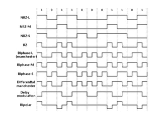
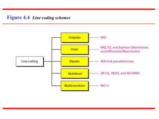
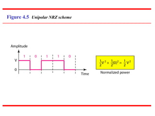
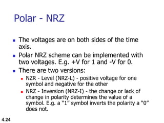
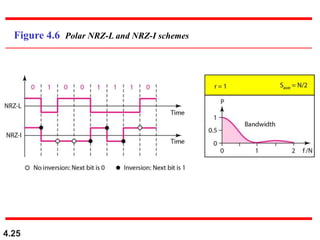
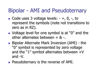
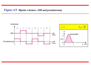
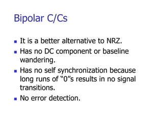
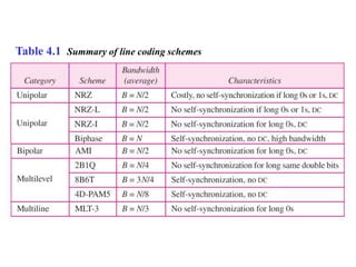
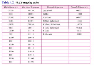
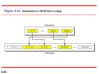
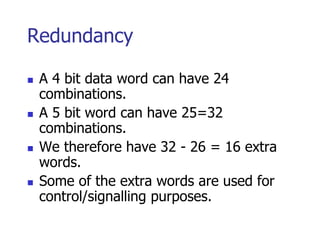
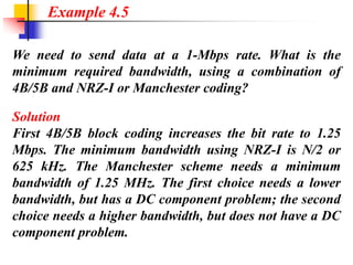
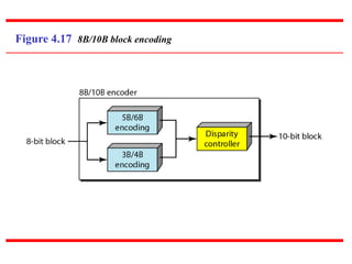
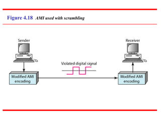
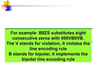
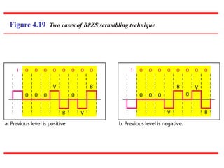
2. DIGITAL-TO-DIGITAL CONVERSION
In this section, we see how we can represent digital
data by using digital signals. The conversion involves
three techniques: line coding, block coding, and
scrambling. Line coding is always needed; block
coding and scrambling may or may not be needed.
Line Coding
Line Coding Schemes
Block Coding
Scrambling
Topics discussed in this section:
3.
4. Line Coding
Converting a string of 1’s and 0’s
(digital data) into a sequence of signals
that denote the 1’s and 0’s.
For example a high voltage level (+V)
could represent a “1” and a low voltage
level (0 or -V) could represent a “0”.
6. Mapping Data symbols onto
Signal levels
A data symbol (or element) can consist of a
number of data bits:
1 , 0 or
11, 10, 01, ……
A data symbol can be coded into a single
signal element or multiple signal elements
1 -> +V, 0 -> -V
1 -> +V and -V, 0 -> -V and +V
The ratio ‘r’ is the number of data elements
carried by a signal element.
7. Relationship between data
rate and signal rate
The data rate defines the number of bits sent
per sec - bps. It is often referred to the bit
rate.
The signal rate is the number of signal
elements sent in a second and is measured in
bauds. It is also referred to as the modulation
rate.
Goal is to increase the data rate whilst
reducing the baud rate.
9. Data rate and Baud rate
The baud or signal rate can be
expressed as:
S = c x N x 1/r bauds
where N is data rate
c is the case factor (worst, best & avg.)
r is the ratio between data element &
signal element
10. A signal is carrying data in which one data element is
encoded as one signal element ( r = 1). If the bit rate is
100 kbps, what is the average value of the baud rate if c is
between 0 and 1?
Solution
We assume that the average value of c is 1/2 . The baud
rate is then
Example 4.1
11. Although the actual bandwidth of a
digital signal is infinite, the effective
bandwidth is finite.
Note
12. 4.12
The maximum data rate of a channel (see Chapter 3) is
Nmax = 2 × B × log2 L (defined by the Nyquist formula).
Does this agree with the previous formula for Nmax?
Solution
A signal with L levels actually can carry log2L bits per
level. If each level corresponds to one signal element and
we assume the average case (c = 1/2), then we have
Example 4.2
13. 4.13
Considerations for choosing a good
signal element referred to as line
encoding
Baseline wandering - a receiver will evaluate
the average power of the received signal
(called the baseline) and use that to determine
the value of the incoming data elements. If
the incoming signal does not vary over a long
period of time, the baseline will drift and thus
cause errors in detection of incoming data
elements.
A good line encoding scheme will prevent long
runs of fixed amplitude.
14. Line encoding C/Cs
DC components - when the voltage
level remains constant for long periods
of time, there is an increase in the low
frequencies of the signal. Most channels
are bandpass and may not support the
low frequencies.
This will require the removal of the dc
component of a transmitted signal.
15. 4.15
Line encoding C/Cs
Self synchronization - the clocks at the
sender and the receiver must have the
same bit interval.
If the receiver clock is faster or slower it
will misinterpret the incoming bit
stream.
17. In a digital transmission, the receiver clock is 0.1 percent
faster than the sender clock. How many extra bits per
second does the receiver receive if the data rate is
1 kbps? How many if the data rate is 1 Mbps?
Solution
At 1 kbps, the receiver receives 1001 bps instead of 1000
bps.
Example 4.3
At 1 Mbps, the receiver receives 1,001,000 bps instead of
1,000,000 bps.
18. Line encoding C/Cs
Error detection - errors occur during
transmission due to line impairments.
Some codes are constructed such that
when an error occurs it can be
detected. For example: a particular
signal transition is not part of the code.
When it occurs, the receiver will know
that a symbol error has occurred.
19. Line encoding C/Cs
Noise and interference - there are line
encoding techniques that make the
transmitted signal “immune” to noise
and interference.
This means that the signal cannot be
corrupted, it is stronger than error
detection.
20. Line encoding C/Cs
Complexity - the more robust and
resilient the code, the more complex it
is to implement and the price is often
paid in baud rate or required
bandwidth.
22. Unipolar
All signal levels are on one side of the time
axis - either above or below
NRZ - Non Return to Zero scheme is an
example of this code. The signal level does
not return to zero during a symbol
transmission.
Scheme is prone to baseline wandering and
DC components. It has no synchronization or
any error detection. It is simple but costly in
power consumption.
24. 4.24
Polar - NRZ
The voltages are on both sides of the time
axis.
Polar NRZ scheme can be implemented with
two voltages. E.g. +V for 1 and -V for 0.
There are two versions:
NZR - Level (NRZ-L) - positive voltage for one
symbol and negative for the other
NRZ - Inversion (NRZ-I) - the change or lack of
change in polarity determines the value of a
symbol. E.g. a “1” symbol inverts the polarity a “0”
does not.
26. In NRZ-L the level of the voltage
determines the value of the bit.
In NRZ-I the inversion
or the lack of inversion
determines the value of the bit.
Note
28. NRZ-L and NRZ-I both have a DC
component problem and baseline
wandering, it is worse for NRZ-L. Both
have no self synchronization &no error
detection. Both are relatively simple to
implement.
Note
29. A system is using NRZ-I to transfer 1-Mbps data. What
are the average signal rate and minimum bandwidth?
Solution
The average signal rate is S= c x N x R = 1/2 x N x 1 =
500 kbaud. The minimum bandwidth for this average
baud rate is Bmin = S = 500 kHz.
Note c = 1/2 for the avg. case as worst case is 1 and best
case is 0
Example 4.4
30. 4.30
Polar - RZ
The Return to Zero (RZ) scheme uses three
voltage values. +, 0, -.
Each symbol has a transition in the middle.
Either from high to zero or from low to zero.
This scheme has more signal transitions (two
per symbol) and therefore requires a wider
bandwidth.
No DC components or baseline wandering.
Self synchronization - transition indicates
symbol value.
More complex as it uses three voltage level.
It has no error detection capability.
32. Polar - Biphase: Manchester and
Differential Manchester
Manchester coding consists of combining the
NRZ-L and RZ schemes.
Every symbol has a level transition in the middle:
from high to low or low to high. Uses only two
voltage levels.
Differential Manchester coding consists of
combining the NRZ-I and RZ schemes.
Every symbol has a level transition in the middle.
But the level at the beginning of the symbol is
determined by the symbol value. One symbol
causes a level change the other does not.
33. Figure 4.8 Polar biphase: Manchester and differential Manchester schemes
34. 4.34
In Manchester and differential
Manchester encoding, the transition
at the middle of the bit is used for
synchronization.
Note
35. 4.35
The minimum bandwidth of Manchester
and differential Manchester is 2 times
that of NRZ. The is no DC component
and no baseline wandering. None of
these codes has error detection.
Note
36. Bipolar - AMI and Pseudoternary
Code uses 3 voltage levels: - +, 0, -, to
represent the symbols (note not transitions to
zero as in RZ).
Voltage level for one symbol is at “0” and the
other alternates between + & -.
Bipolar Alternate Mark Inversion (AMI) - the
“0” symbol is represented by zero voltage
and the “1” symbol alternates between +V
and -V.
Pseudoternary is the reverse of AMI.
38. Bipolar C/Cs
It is a better alternative to NRZ.
Has no DC component or baseline
wandering.
Has no self synchronization because
long runs of “0”s results in no signal
transitions.
No error detection.
40. Block Coding
For a code to be capable of error detection, we need
to add redundancy, i.e., extra bits to the data bits.
Synchronization also requires redundancy -
transitions are important in the signal flow and must
occur frequently.
Block coding is done in three steps: division,
substitution and combination.
It is distinguished from multilevel coding by use of
the slash - xB/yB.
The resulting bit stream prevents certain bit
combinations that when used with line encoding
would result in DC components or poor sync. quality.
41. 4.41
Block coding is normally referred to as
mB/nB coding;
it replaces each m-bit group with an
n-bit group.
Note
46. Redundancy
A 4 bit data word can have 24
combinations.
A 5 bit word can have 25=32
combinations.
We therefore have 32 - 26 = 16 extra
words.
Some of the extra words are used for
control/signalling purposes.
47. We need to send data at a 1-Mbps rate. What is the
minimum required bandwidth, using a combination of
4B/5B and NRZ-I or Manchester coding?
Solution
First 4B/5B block coding increases the bit rate to 1.25
Mbps. The minimum bandwidth using NRZ-I is N/2 or
625 kHz. The Manchester scheme needs a minimum
bandwidth of 1.25 MHz. The first choice needs a lower
bandwidth, but has a DC component problem; the second
choice needs a higher bandwidth, but does not have a DC
component problem.
Example 4.5
49. More bits - better error detection
The 8B10B block code adds more
redundant bits and can thereby choose
code words that would prevent a long
run of a voltage level that would cause
DC components.
50. Scrambling
The best code is one that does not increase
the bandwidth for synchronization and has no
DC components.
Scrambling is a technique used to create a
sequence of bits that has the required c/c’s for
transmission - self clocking, no low
frequencies, no wide bandwidth.
It is implemented at the same time as
encoding, the bit stream is created on the fly.
It replaces ‘unfriendly’ runs of bits with a
violation code that is easy to recognize and
removes the unfriendly c/c.
52. For example: B8ZS substitutes eight
consecutive zeros with 000VB0VB.
The V stands for violation, it violates the
line encoding rule
B stands for bipolar, it implements the
bipolar line encoding rule
54. HDB3 substitutes four consecutive
zeros with 000V or B00V depending
on the number of nonzero pulses after
the last substitution.
If # of non zero pulses is even the
substitution is B00V to make total # of
non zero pulse even.
If # of non zero pulses is odd the
substitution is 000V to make total # of
non zero pulses even.