Downloaded 116 times

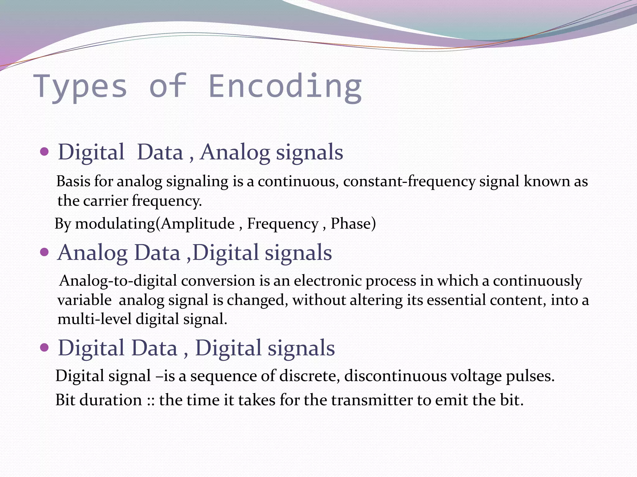
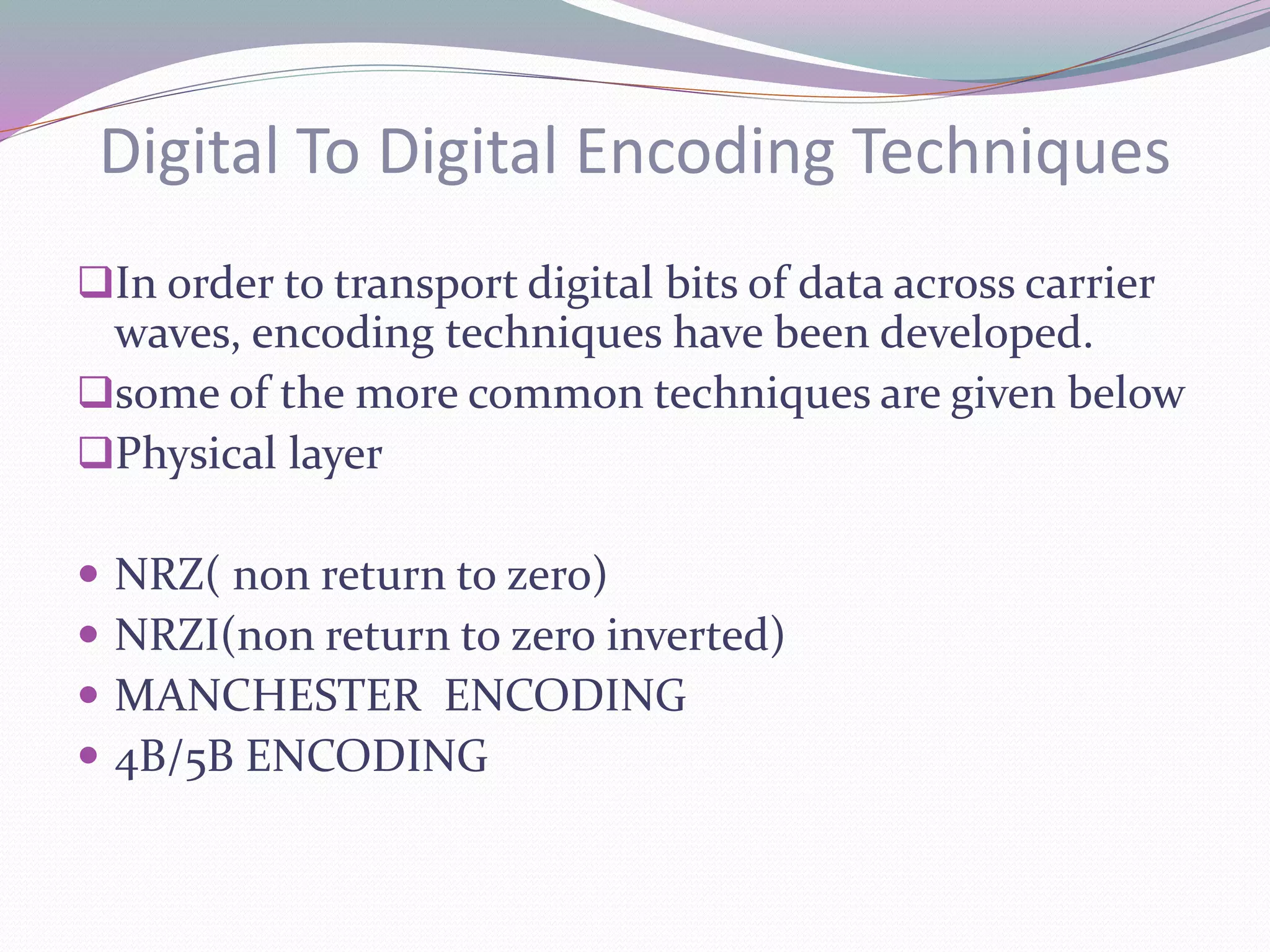
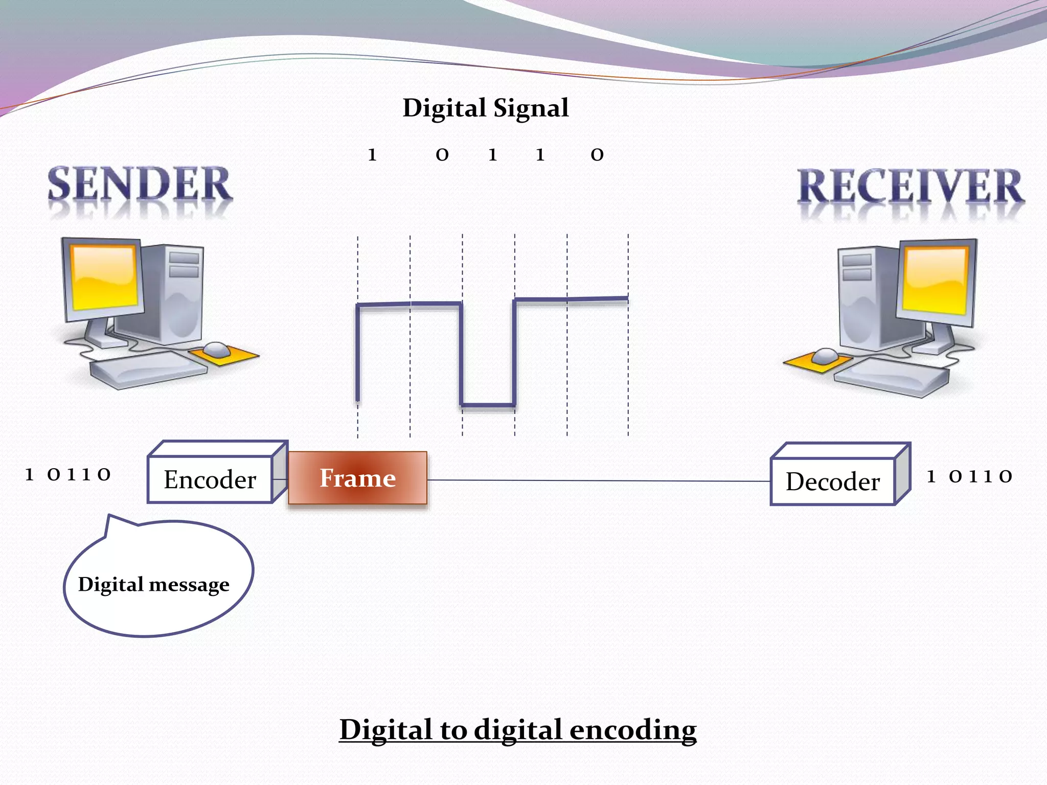
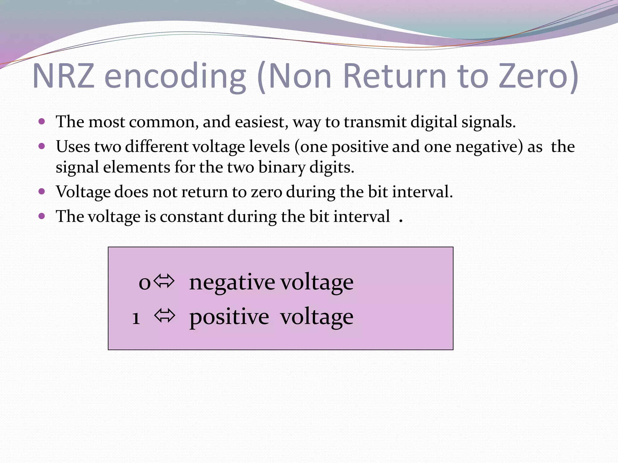
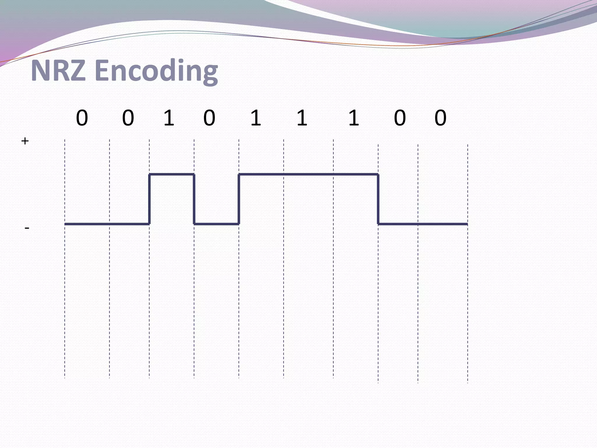
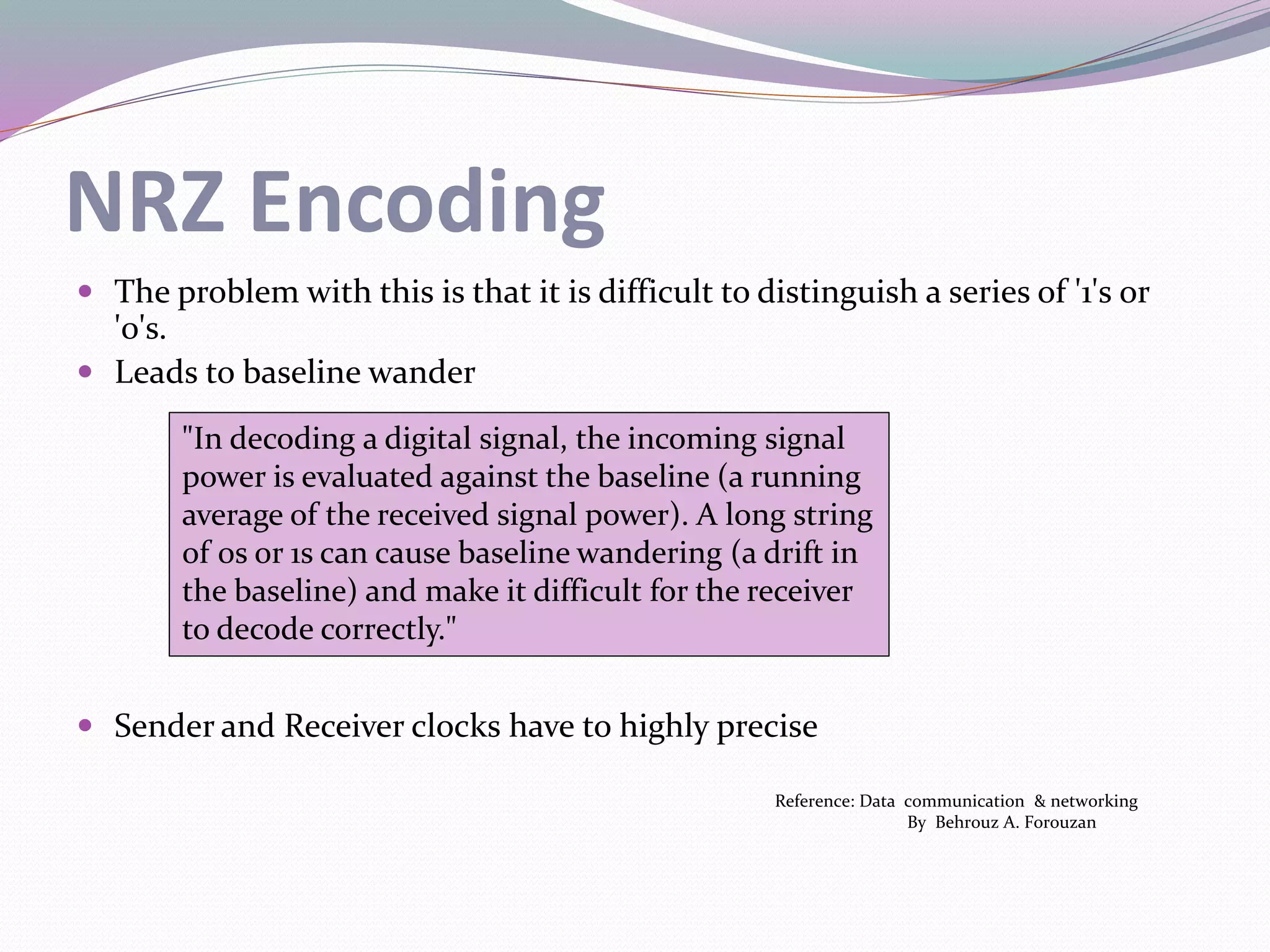
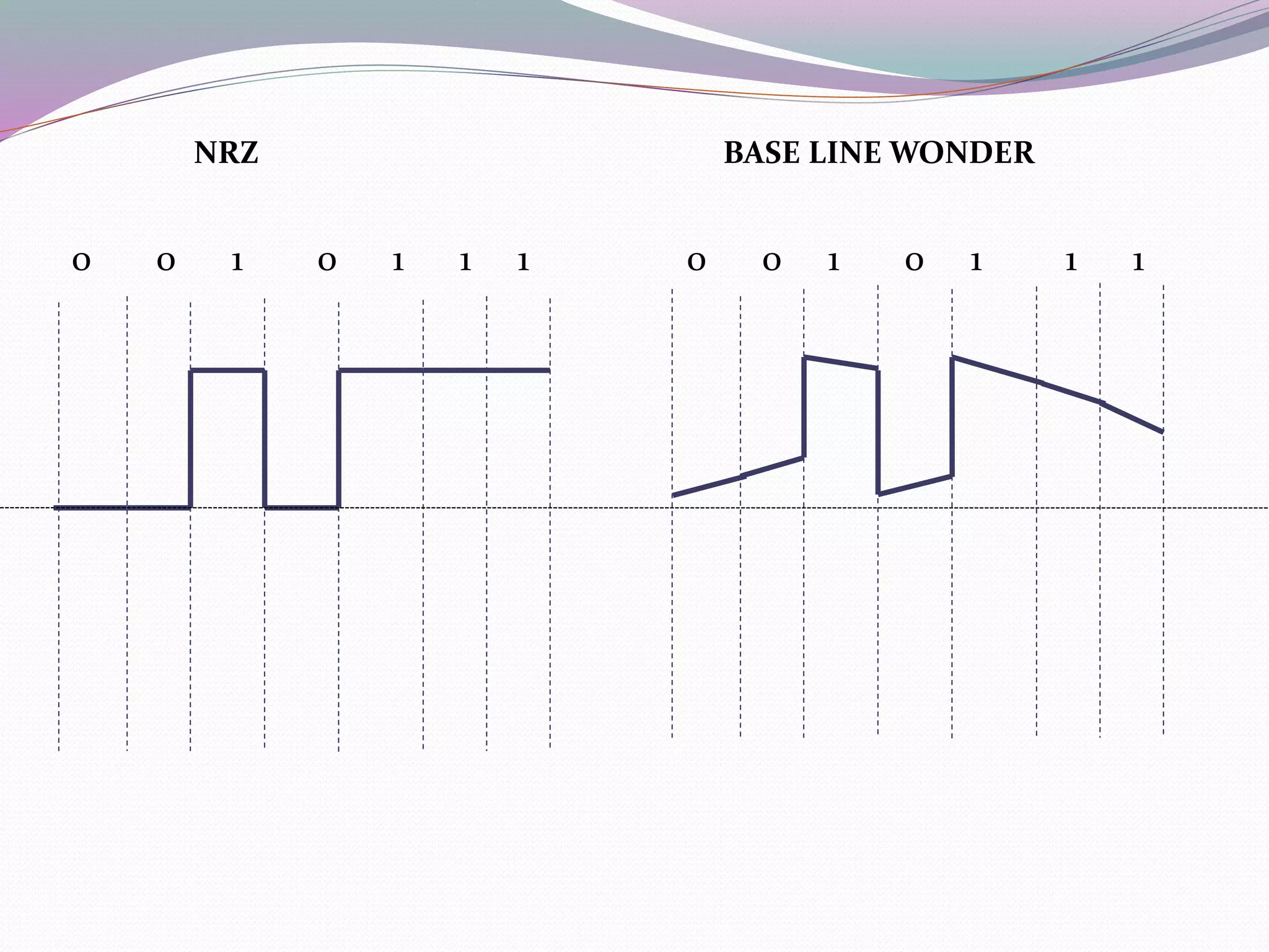
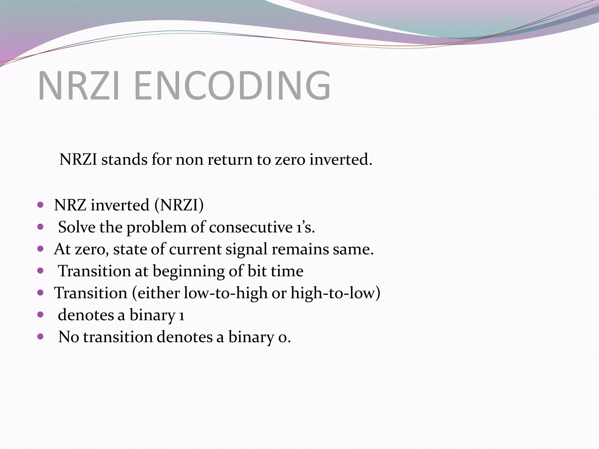
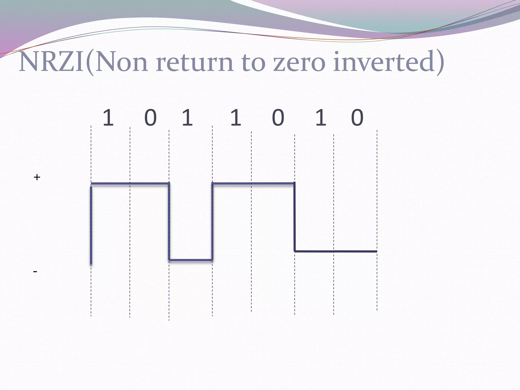
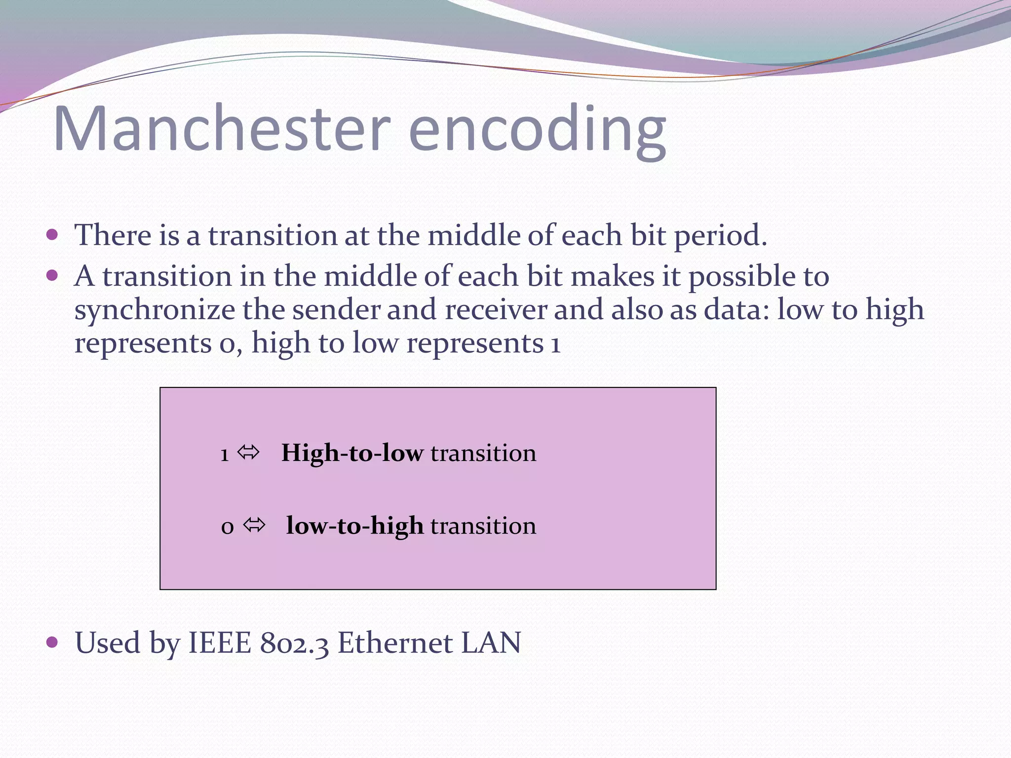
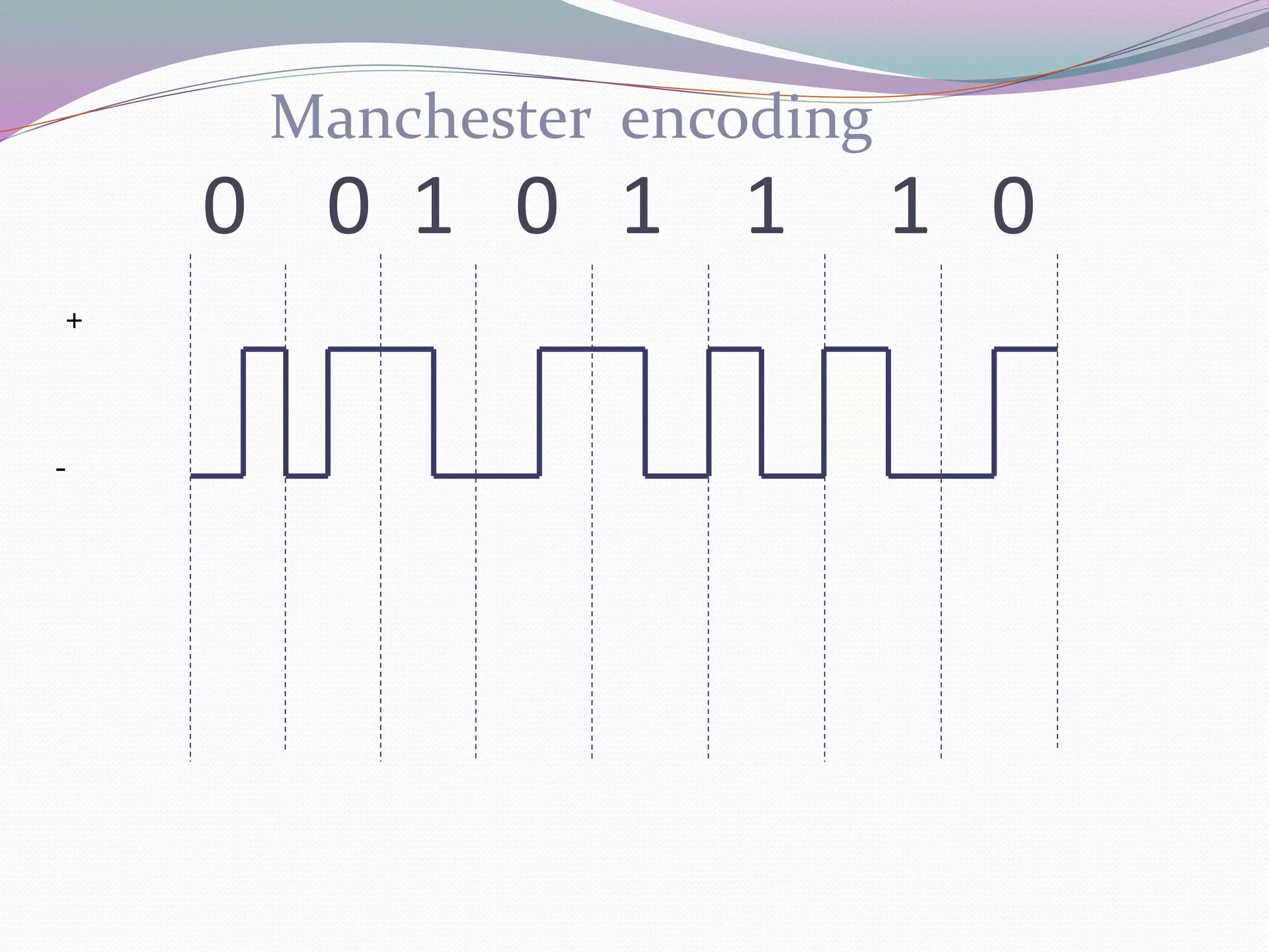
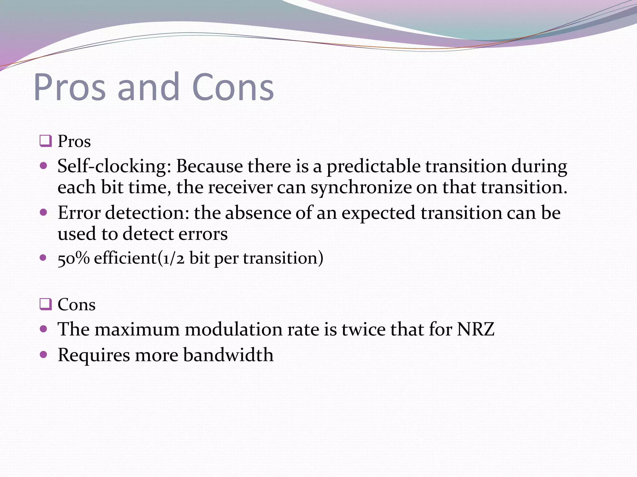
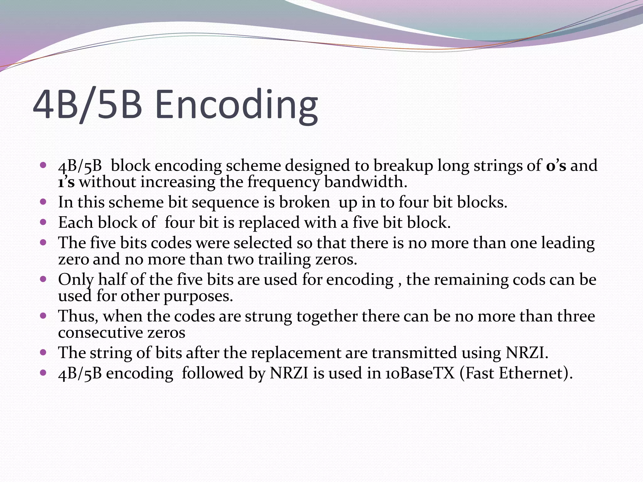
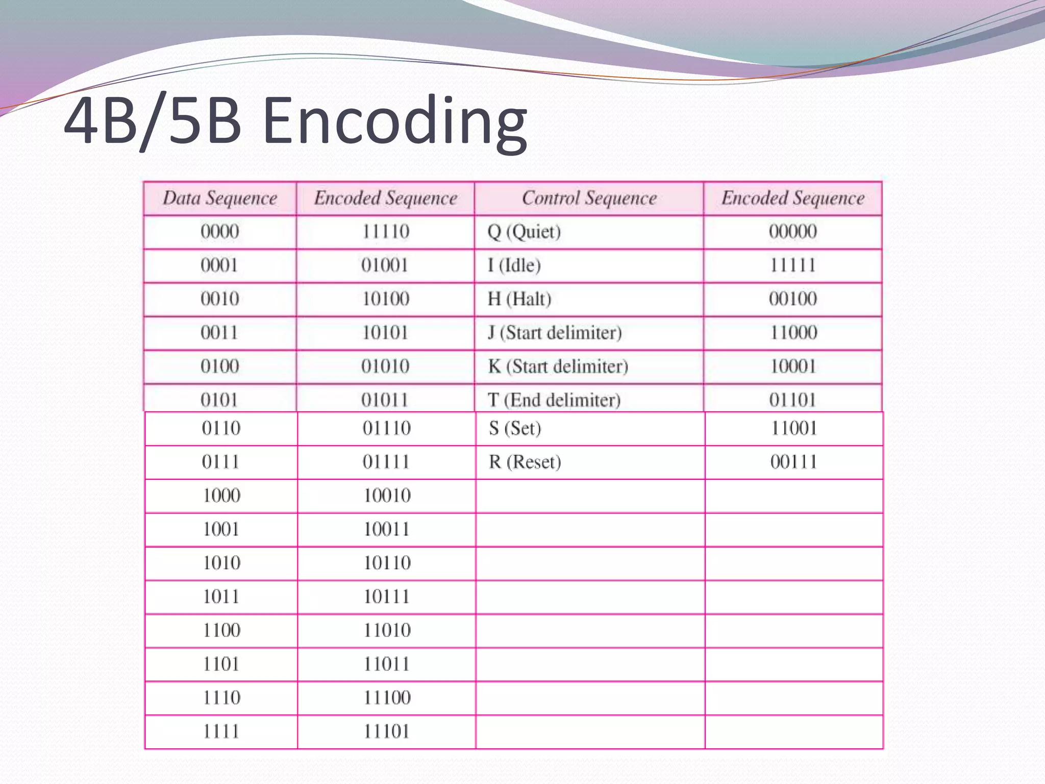
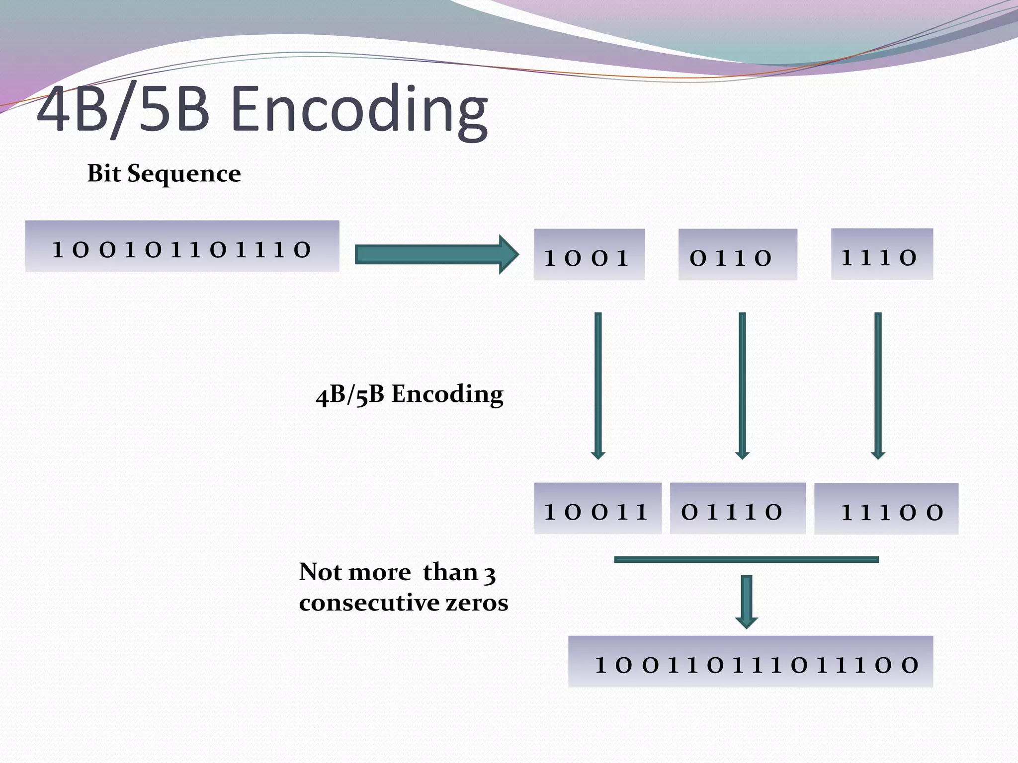
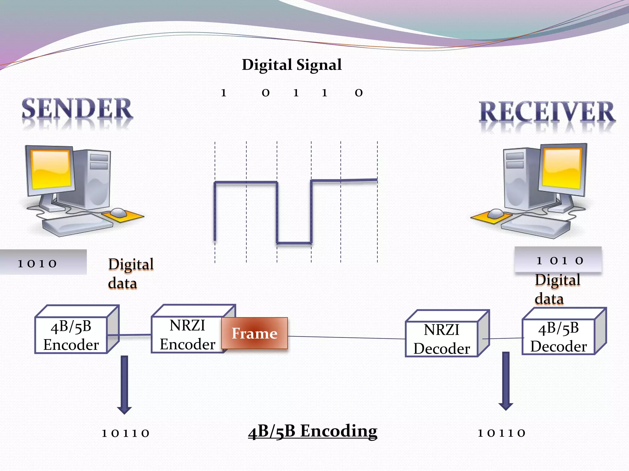

Encoding is the process of converting data into a digital format for transmission. There are different encoding techniques for analog and digital signals. Common digital to digital encoding techniques include NRZ, NRZI, Manchester, and 4B/5B encoding. NRZ assigns a voltage level to represent each bit but can result in baseline wander with long strings of 1s or 0s. NRZI and Manchester encoding add transitions to allow for clocking but require more bandwidth. 4B/5B encoding maps 4-bit groups to 5-bit codes to avoid long runs of the same bit.


![Coded Agents – with UiPath SDK + LangGraph [Virtual Hands-on Workshop]](https://cdn.slidesharecdn.com/ss_thumbnails/codedagentsdeck-251215155422-5497c599-thumbnail.jpg?width=640&height=640&fit=bounds)


![Vibe Coding vs. Spec-Driven Development [Free Meetup]](https://cdn.slidesharecdn.com/ss_thumbnails/vibecodingvsspecdrivendevelopment-251209105622-43f455e7-thumbnail.jpg?width=640&height=640&fit=bounds)