Downloaded 259 times

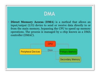
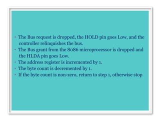
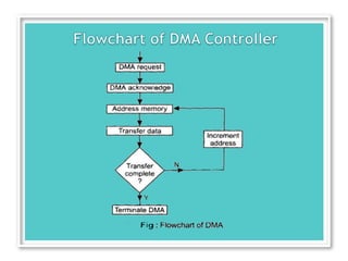
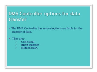
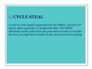


1. Direct Memory Access (DMA) allows input/output devices to directly access main memory, bypassing the CPU to speed up memory transfers. This is managed by a DMA controller. 2. During a DMA transfer, the DMA controller gains control of the address bus, data bus, and control bus from the microprocessor to transfer data directly between an I/O port and memory. 3. The DMA controller has several options for transferring data, including cycle stealing for single byte transfers, burst mode for block transfers using address sequencing, and hidden DMA which occurs transparently when the CPU is not using the bus.


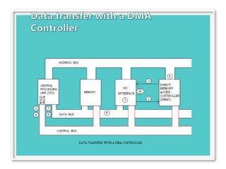
![30128-influencer-marketing-pitch-deck[1].pptx](https://cdn.slidesharecdn.com/ss_thumbnails/30128-influencer-marketing-pitch-deck1-240529185830-498e0917-thumbnail.jpg?width=640&height=640&fit=bounds)


