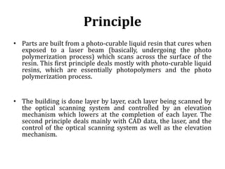
VNR Vignana Jyothi Institute of Engineering and Technology,
Hyderabad
Subject: Digital Fabrication
Department of Mechanical Engineering
Name Gourav Tiwari
Designation Assistant Professor
Year/semester III Year B.Tech I Semester
Subject Code 5ME71
Topic Processes
Sub. Topic SLA, SLS, FDM
Stereolithography
Apparatus (SLA)
2
PHOTO-FABRICATION
MATERIALS CURING PROCESS
Acrylate &
methacrylate
Free radical
polymerization
Epoxides & vinyl
ethers
Cationic
polymerization
Hybrid ( Acrylate +
Epoxy)
Radical + Cationic
polymerization
3
Photo Polymerization Process
DEFINITION OF STEREOLITHOGRAPHY
Stereo lithography is an additive manufacturing or 3D
printing technology used for producing models prototypes , patterns,
and production parts up one layer at a time by curing a photo-reactive
resin with a UV laser or another similar power source.
Methods Employed:
• Top-down approach
• Bottom-up approach
POST-PROCESSING:
• Post curing/ de-binding/ sintering process for increasing
mechanical properties
5
Top- Down
Approach
Bottom- Up
Approach
Fig . 1
Fig.2
7
Vector scanning
8
Principle
• Parts are built from a photo-curable liquid resin that cures when
exposed to a laser beam (basically, undergoing the photo
polymerization process) which scans across the surface of the
resin. This first principle deals mostly with photo-curable liquid
resins, which are essentially photopolymers and the photo
polymerization process.
• The building is done layer by layer, each layer being scanned by
the optical scanning system and controlled by an elevation
mechanism which lowers at the completion of each layer. The
second principle deals mainly with CAD data, the laser, and the
control of the optical scanning system as well as the elevation
mechanism.
Advantages
• Round the clock operation.
• Good user support.
• Build volumes.
• Good accuracy.
• Surface finish.
• Wide range of materials.
10
Disadvantages
• Requires support structures.
• Requires post-processing.
• Requires post-curing.
11
APPLICATIONS
• Models for conceptualization, packaging and presentation.
• Prototypes for design, analysis, verification and functional
testing.
• Parts for prototype tooling and low volume production tooling.
• Patterns for investment casting, sand casting and molding.
• Tools for fixture and tooling design, and production tooling.
12
Industrial Applications
• Ford Uses Stereo lithography to Cast Prototype Tooling.
• Black & Decker Saves a Year by Using Stereo lithography to
Prototype their Improved Shearer/Shrub Trimmer Power
Tool.
• Bose Saves Five Weeks Using Stereo lithography Over
Traditional Hard Tooling
13
METALLIC STEREOLITHOGRAPHY
Metallic
Powder
Dispersant
Homogenous
Metallic
Suspension
Diluents
Pre-polymer and
photo-initiator
Metallic Matrix
De-binding
&
Sintering
Final Part
16
HYBRID METALLIC RESIN
Unsaturated Polyester
• High resistance
• Thermal stability
• Hardness
• Flexibility
Epoxy
• High elasticity
module,
• Excellent thermo and
mechanical
properties
• Low viscosity
• Low shrinkage
+
17
CURING BEHAVIOUR:
• The rise in light intensity increases the reaction rate
• The conversion rate increases rapidly followed by a progressive slowing
down until the cure profile reaches a plateau.
• This progressive slowing down is due to diffusion limitations because of
increase in cross-link density.
Fig. 3 Variation of fractional
conversion Vs. curing time
18
Microstereolithography
19
Micro Stereolithography – Specifications
and Limitations
20
• Positioning stage must move slow
• Maximum component resolution is approximately 0.1 mm
• Requires manipulation and micro-assembly of micro-parts
• 5- µm spot size of the UV beam
• Positional accuracy is 0.25 µm (in the x–y directions) and 1.0 µm
in the
• z-direction
• Minimum size of the unit of hardened polymer is 5 µm * 5 µm * 3
µm (in x, y, z)
• Maximum size of fabrication structure is 10 mm *10 mm * 10
mm
• Uses vector or line scanning
• Not suitable for “real” 3D products
Micro-assembly
21
Micro Stereolithography Products
22
Powder Bed Fusion (PBF) Process
 Developed at University of Texas at Austin, USA by Carl Deckard
(master’s thesis) in 1989 with the process called selective laser
sintering (SLS)
 Characteristics of PBF process
 Thermal source for inducing fusion between powder particles
 Controlling powder fusion to a prescribed region of each layer
 Mechanism for adding and smoothing powder layers
 Materials: polymers, metals, ceramics and composites
 Direct Digital Manufacturing of end-use products
Selective Laser Sintering (SLS) Process
 Layer thickness: 0.1 mm
 Nitrogen gas
 Below melting point temp
 Focused Co2 Laser
 Thermal fusion/melting/sintering
 No supports are needed
 Cool-down period
 Post-processing
Binding/Fusion Mechanisms of PBF Processes
Solid State Sintering
Chemically-induced Sintering
 Thermally-activated chemical reaction between two types of powders/
between powders and atmospheric gases to form by-product which binds
the powders together
 Ceramic materials
 Laser processing of SiC in presence of oxygen, SiO2 forms and binds
together a composite SiC & SiO2
 By adding chemical reaction energy to laser energy, high-melting-
temperature structures can be created
 Part porosity/post-process infiltration/high temperature furnace
sintering
Liquid-phase Sintering(Partial Melting)
 Most versatile for PBF process
 Molten (glue) + solid
 High temp. particles can be bounded without melting directly
 Darker regions: low-melting-temp. binder material
 Lighter regions: high-melting-temp. structure material
 Types of LPS:
 Separate particles (polymer binders/post-processing)
 Composite particles (polymer+metal/ceramic)
 Coated particles (better absorption of laser power, effective binding)
 Indistinct mixture (non-eutectic alloys/liquidus and solidus temp.)
Full Melting
 Most common PBF process of engineering metal alloys & semi-
crystalline polymers (nylon-polyamide)
 Entire region of material subjected to heat energy
 Well-bonded/high density structures from metals
 Ti, Stainless Steel, CoCr, etc.
 Rapid melting and solidification: Unique properties
 More desirable than Cast/wrought parts made from identical
alloys
Powder Handling Systems
Hooper based powder delivery systems
Counter-rotating roller powder delivery system
Powder Handling Challenges
 Powder reservoir of sufficient volume to build maximum build height
without refill
 Correct volume of powder must be transported to the build platform
without wasteful excess material
 Powder must be spread to form a smooth, thin, repeatable layer of powder
 Powder spreading must not create excessive shear forces that disturb the
previously processed layers
 Particle size decreases: interparticle friction and electrostatic forces
increases: lose of flowability
 Surface area to volume ratio of a particle increases: surface energy
increases: more reactive: explosive: inert gas
 Small particles: airborne: floats as a cloud of particles: damage the moving
parts: better surface finish: higher accuracy: thinner layers
Powder Recycling
 Elevated temperatures: reacting atmospheric gases: Change the chemical
nature of the powder particles
 Change of particle size and molecular weight
 1/3 unused powder
 Particle sorting methods: Vibratory screen-based sifting/ air classifier
 Consistent builds: Powder’s melt flow index (MFI)
 MFI for unused & used powders
 Recyclability of a powder and the target MFI/fraction mixing have a
significant effect on part properties & cost
Specifications of 3D System Sinterstation
HiQ and Pro
34
3D Systems Selective Laser Sintering(SLS):
Products
 Sinterstation HiQ Systems
 Sinterstation 2500plus
 Sinterstation Pro
35
3D Systems Selective Laser Sintering(SLS):
Materials
 CastForm: It is similar to standard investment casting wax used by
foundries
 DuraForm: It is a polycarbonate, industry standard, engineering
thermoplastic. DuraForm PA, DuraForm GF
 Nylon: Durable material
 Somos 201: Rubber/elastomer/flexible
 LaserForm ST-100: 60% Steel + 40% Bronze
36
3D Systems Selective Laser Sintering (SLS):
Strengths
 Good part stability: Functional parts build directly
 Wide range of materials: nylon/polycarbonates/metals/ceramics
 No part supports required
 Little post-processing required: particle blasting/sanding
 No post-curing required
 Advanced software support
37
3D Systems Selective Laser Sintering (SLS):
Weaknesses
 Large physical size of the unit
 High power consumption
 Poor surface finish
Applications of SLS
 Concept Models
 Functional models and working prototypes
 Polycarbonate patterns
 Metal Tools
39
SLS Applications:
Functional Prototypes
 DuraForm PA, GF, and SOMOS 201
TPE
 Outstanding durability – mechanical,
thermal, chemical
 Allow aggressive “real-world” testing
 End-use parts for some low-volume
applications
 Future direction = metals
40
SLS Applications: Investment
Casting
 CastForm PS
 Direct expendable patterns
 Production-equivalent
prototypes and low-volume
manufacturing
 Standard foundry processing
 Cast all metals, even reactive
metals like titanium
41
SLS Applications: Sand Casting
 SandForm Si and Zr
 Direct shell sand cores and
molds
 Production-equivalent
prototypes and low-volume
manufacturing
 Unlimited complexity – difficult
to manufacture parts
42
SLS Applications: Metal Tooling
 RapidSteel 2.0
 “Direct from CAD” near-net shape tools in
4-5 days
 Molded parts in as little
as 2 weeks
 Rapid turnaround prototype injection
molded and die cast parts
 Low volume (< 100,000) production
injection molding
Research and Development of SLS
 Developing new and advanced materials
 Improving and refining process
 OptiScan software: Reduced build time by 34%
Solid foil polymerization (SFP)
The part is built up using semi-polymerized foils
which are soluble in monomer resin. On
exposure to UV light, the foil solidifies and
bonds to the previous layer. It also becomes
insoluble. Once the cross-sect ion has been
illuminated, a new foil can be applied. The
unwanted material acts as support and can be
removed later.

Additive manufacturing ppt2

  • 1.
    VNR Vignana JyothiInstitute of Engineering and Technology, Hyderabad Subject: Digital Fabrication Department of Mechanical Engineering Name Gourav Tiwari Designation Assistant Professor Year/semester III Year B.Tech I Semester Subject Code 5ME71 Topic Processes Sub. Topic SLA, SLS, FDM
  • 2.
  • 3.
    PHOTO-FABRICATION MATERIALS CURING PROCESS Acrylate& methacrylate Free radical polymerization Epoxides & vinyl ethers Cationic polymerization Hybrid ( Acrylate + Epoxy) Radical + Cationic polymerization 3
  • 4.
  • 5.
    DEFINITION OF STEREOLITHOGRAPHY Stereolithography is an additive manufacturing or 3D printing technology used for producing models prototypes , patterns, and production parts up one layer at a time by curing a photo-reactive resin with a UV laser or another similar power source. Methods Employed: • Top-down approach • Bottom-up approach POST-PROCESSING: • Post curing/ de-binding/ sintering process for increasing mechanical properties 5
  • 7.
  • 8.
  • 9.
    Principle • Parts arebuilt from a photo-curable liquid resin that cures when exposed to a laser beam (basically, undergoing the photo polymerization process) which scans across the surface of the resin. This first principle deals mostly with photo-curable liquid resins, which are essentially photopolymers and the photo polymerization process. • The building is done layer by layer, each layer being scanned by the optical scanning system and controlled by an elevation mechanism which lowers at the completion of each layer. The second principle deals mainly with CAD data, the laser, and the control of the optical scanning system as well as the elevation mechanism.
  • 10.
    Advantages • Round theclock operation. • Good user support. • Build volumes. • Good accuracy. • Surface finish. • Wide range of materials. 10
  • 11.
    Disadvantages • Requires supportstructures. • Requires post-processing. • Requires post-curing. 11
  • 12.
    APPLICATIONS • Models forconceptualization, packaging and presentation. • Prototypes for design, analysis, verification and functional testing. • Parts for prototype tooling and low volume production tooling. • Patterns for investment casting, sand casting and molding. • Tools for fixture and tooling design, and production tooling. 12
  • 13.
    Industrial Applications • FordUses Stereo lithography to Cast Prototype Tooling. • Black & Decker Saves a Year by Using Stereo lithography to Prototype their Improved Shearer/Shrub Trimmer Power Tool. • Bose Saves Five Weeks Using Stereo lithography Over Traditional Hard Tooling 13
  • 16.
  • 17.
    HYBRID METALLIC RESIN UnsaturatedPolyester • High resistance • Thermal stability • Hardness • Flexibility Epoxy • High elasticity module, • Excellent thermo and mechanical properties • Low viscosity • Low shrinkage + 17
  • 18.
    CURING BEHAVIOUR: • Therise in light intensity increases the reaction rate • The conversion rate increases rapidly followed by a progressive slowing down until the cure profile reaches a plateau. • This progressive slowing down is due to diffusion limitations because of increase in cross-link density. Fig. 3 Variation of fractional conversion Vs. curing time 18
  • 19.
  • 20.
    Micro Stereolithography –Specifications and Limitations 20 • Positioning stage must move slow • Maximum component resolution is approximately 0.1 mm • Requires manipulation and micro-assembly of micro-parts • 5- µm spot size of the UV beam • Positional accuracy is 0.25 µm (in the x–y directions) and 1.0 µm in the • z-direction • Minimum size of the unit of hardened polymer is 5 µm * 5 µm * 3 µm (in x, y, z) • Maximum size of fabrication structure is 10 mm *10 mm * 10 mm • Uses vector or line scanning • Not suitable for “real” 3D products
  • 21.
  • 22.
  • 23.
    Powder Bed Fusion(PBF) Process  Developed at University of Texas at Austin, USA by Carl Deckard (master’s thesis) in 1989 with the process called selective laser sintering (SLS)  Characteristics of PBF process  Thermal source for inducing fusion between powder particles  Controlling powder fusion to a prescribed region of each layer  Mechanism for adding and smoothing powder layers  Materials: polymers, metals, ceramics and composites  Direct Digital Manufacturing of end-use products
  • 24.
    Selective Laser Sintering(SLS) Process  Layer thickness: 0.1 mm  Nitrogen gas  Below melting point temp  Focused Co2 Laser  Thermal fusion/melting/sintering  No supports are needed  Cool-down period  Post-processing
  • 25.
  • 26.
  • 27.
    Chemically-induced Sintering  Thermally-activatedchemical reaction between two types of powders/ between powders and atmospheric gases to form by-product which binds the powders together  Ceramic materials  Laser processing of SiC in presence of oxygen, SiO2 forms and binds together a composite SiC & SiO2  By adding chemical reaction energy to laser energy, high-melting- temperature structures can be created  Part porosity/post-process infiltration/high temperature furnace sintering
  • 28.
    Liquid-phase Sintering(Partial Melting) Most versatile for PBF process  Molten (glue) + solid  High temp. particles can be bounded without melting directly  Darker regions: low-melting-temp. binder material  Lighter regions: high-melting-temp. structure material  Types of LPS:  Separate particles (polymer binders/post-processing)  Composite particles (polymer+metal/ceramic)  Coated particles (better absorption of laser power, effective binding)  Indistinct mixture (non-eutectic alloys/liquidus and solidus temp.)
  • 29.
    Full Melting  Mostcommon PBF process of engineering metal alloys & semi- crystalline polymers (nylon-polyamide)  Entire region of material subjected to heat energy  Well-bonded/high density structures from metals  Ti, Stainless Steel, CoCr, etc.  Rapid melting and solidification: Unique properties  More desirable than Cast/wrought parts made from identical alloys
  • 30.
    Powder Handling Systems Hooperbased powder delivery systems Counter-rotating roller powder delivery system
  • 31.
    Powder Handling Challenges Powder reservoir of sufficient volume to build maximum build height without refill  Correct volume of powder must be transported to the build platform without wasteful excess material  Powder must be spread to form a smooth, thin, repeatable layer of powder  Powder spreading must not create excessive shear forces that disturb the previously processed layers  Particle size decreases: interparticle friction and electrostatic forces increases: lose of flowability  Surface area to volume ratio of a particle increases: surface energy increases: more reactive: explosive: inert gas  Small particles: airborne: floats as a cloud of particles: damage the moving parts: better surface finish: higher accuracy: thinner layers
  • 32.
    Powder Recycling  Elevatedtemperatures: reacting atmospheric gases: Change the chemical nature of the powder particles  Change of particle size and molecular weight  1/3 unused powder  Particle sorting methods: Vibratory screen-based sifting/ air classifier  Consistent builds: Powder’s melt flow index (MFI)  MFI for unused & used powders  Recyclability of a powder and the target MFI/fraction mixing have a significant effect on part properties & cost
  • 33.
    Specifications of 3DSystem Sinterstation HiQ and Pro
  • 34.
    34 3D Systems SelectiveLaser Sintering(SLS): Products  Sinterstation HiQ Systems  Sinterstation 2500plus  Sinterstation Pro
  • 35.
    35 3D Systems SelectiveLaser Sintering(SLS): Materials  CastForm: It is similar to standard investment casting wax used by foundries  DuraForm: It is a polycarbonate, industry standard, engineering thermoplastic. DuraForm PA, DuraForm GF  Nylon: Durable material  Somos 201: Rubber/elastomer/flexible  LaserForm ST-100: 60% Steel + 40% Bronze
  • 36.
    36 3D Systems SelectiveLaser Sintering (SLS): Strengths  Good part stability: Functional parts build directly  Wide range of materials: nylon/polycarbonates/metals/ceramics  No part supports required  Little post-processing required: particle blasting/sanding  No post-curing required  Advanced software support
  • 37.
    37 3D Systems SelectiveLaser Sintering (SLS): Weaknesses  Large physical size of the unit  High power consumption  Poor surface finish
  • 38.
    Applications of SLS Concept Models  Functional models and working prototypes  Polycarbonate patterns  Metal Tools
  • 39.
    39 SLS Applications: Functional Prototypes DuraForm PA, GF, and SOMOS 201 TPE  Outstanding durability – mechanical, thermal, chemical  Allow aggressive “real-world” testing  End-use parts for some low-volume applications  Future direction = metals
  • 40.
    40 SLS Applications: Investment Casting CastForm PS  Direct expendable patterns  Production-equivalent prototypes and low-volume manufacturing  Standard foundry processing  Cast all metals, even reactive metals like titanium
  • 41.
    41 SLS Applications: SandCasting  SandForm Si and Zr  Direct shell sand cores and molds  Production-equivalent prototypes and low-volume manufacturing  Unlimited complexity – difficult to manufacture parts
  • 42.
    42 SLS Applications: MetalTooling  RapidSteel 2.0  “Direct from CAD” near-net shape tools in 4-5 days  Molded parts in as little as 2 weeks  Rapid turnaround prototype injection molded and die cast parts  Low volume (< 100,000) production injection molding
  • 43.
    Research and Developmentof SLS  Developing new and advanced materials  Improving and refining process  OptiScan software: Reduced build time by 34%
  • 44.
    Solid foil polymerization(SFP) The part is built up using semi-polymerized foils which are soluble in monomer resin. On exposure to UV light, the foil solidifies and bonds to the previous layer. It also becomes insoluble. Once the cross-sect ion has been illuminated, a new foil can be applied. The unwanted material acts as support and can be removed later.