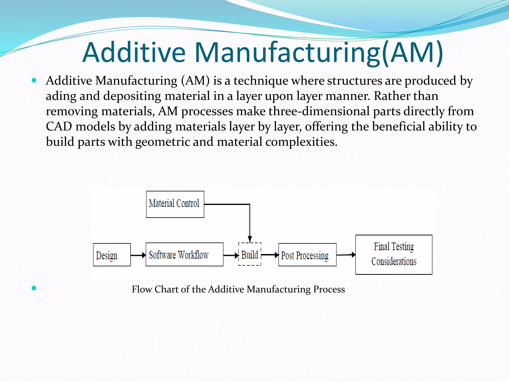
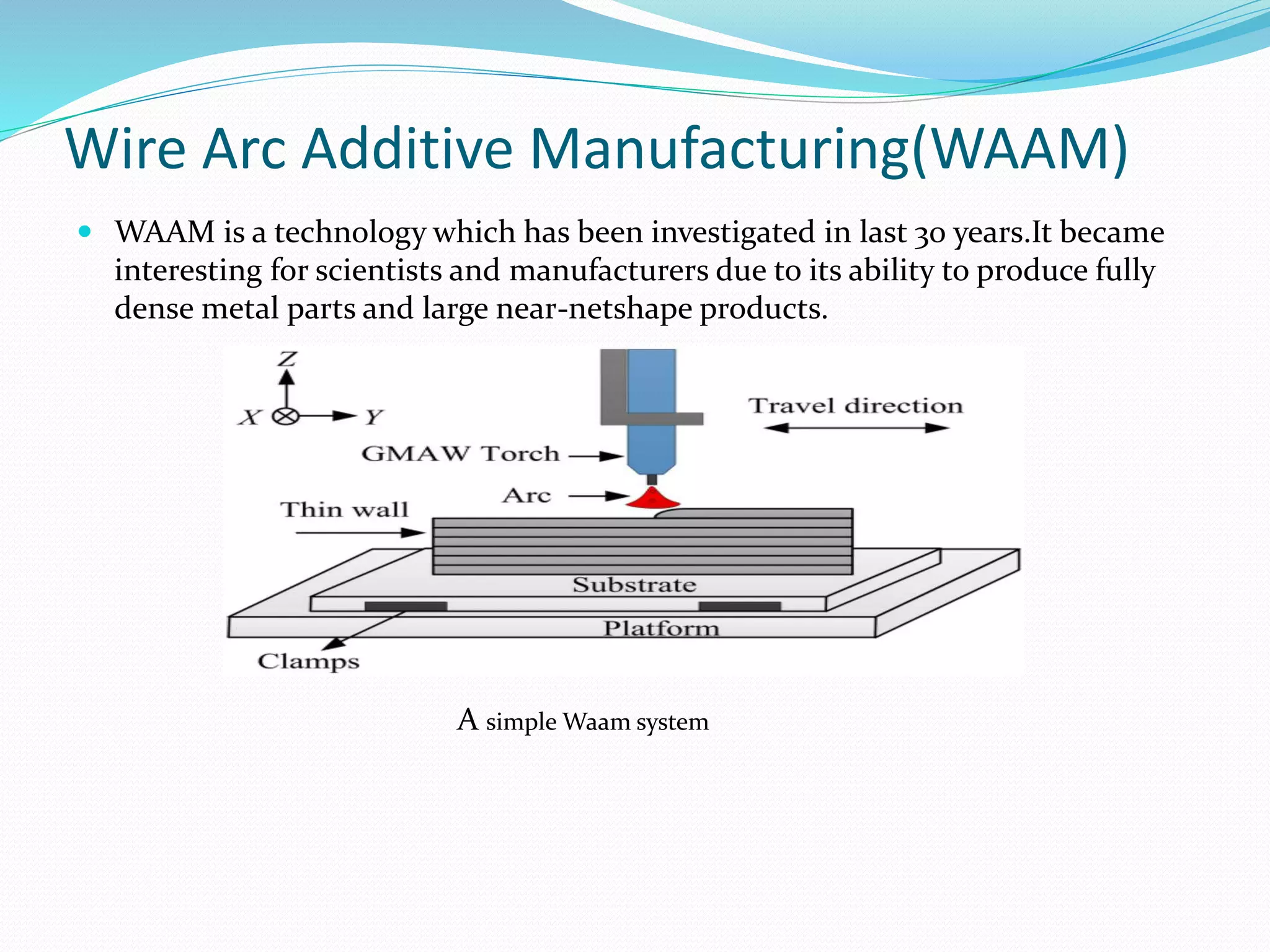
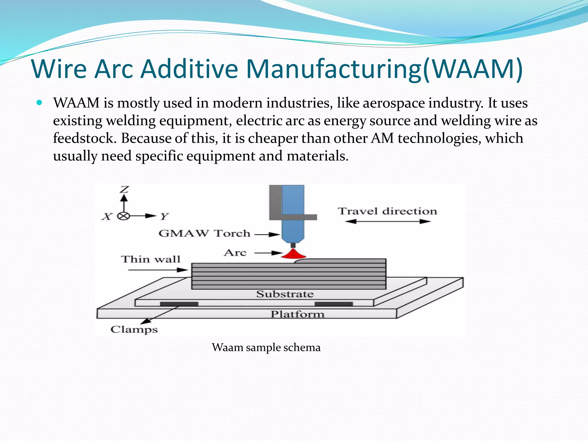
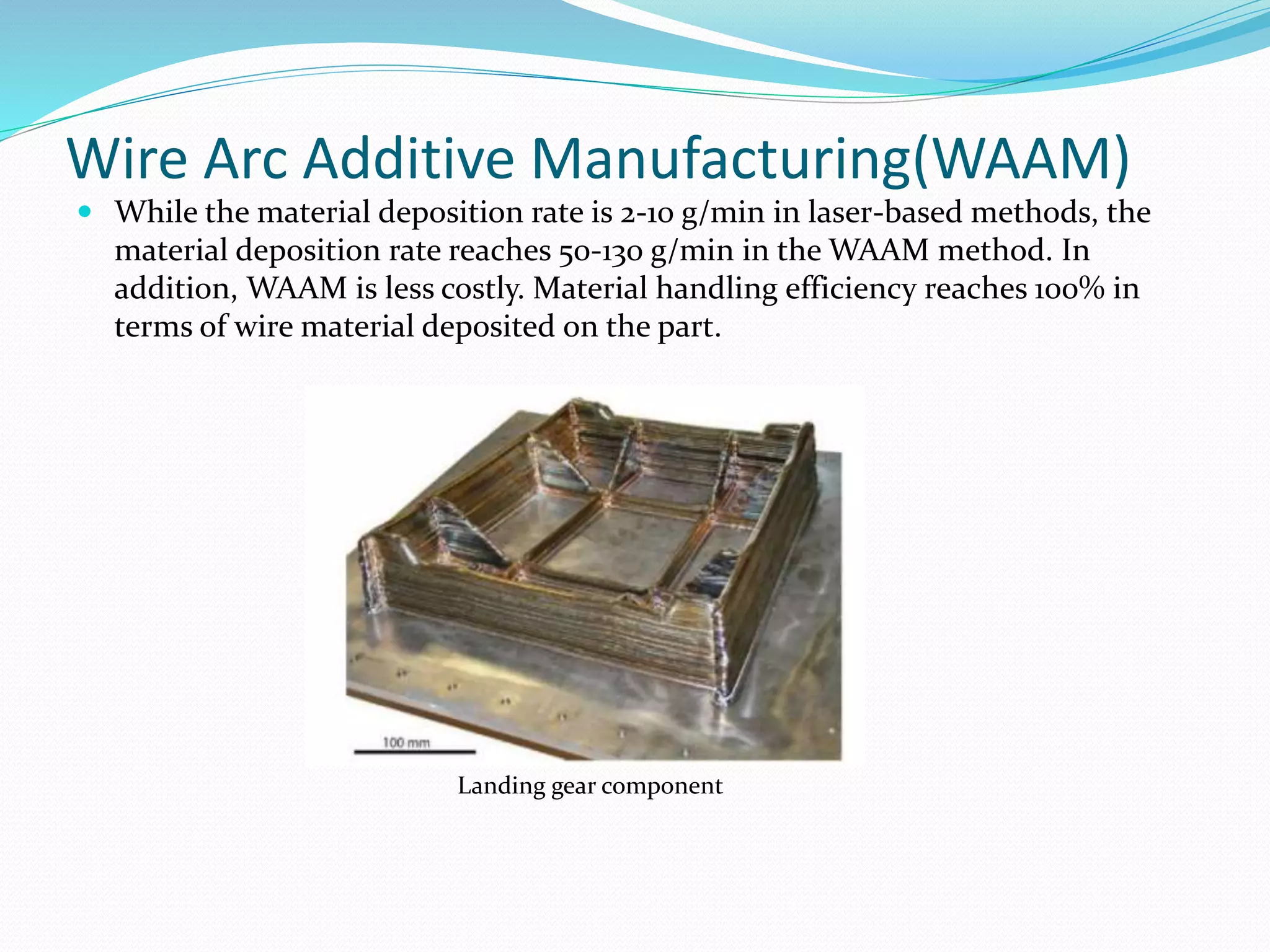
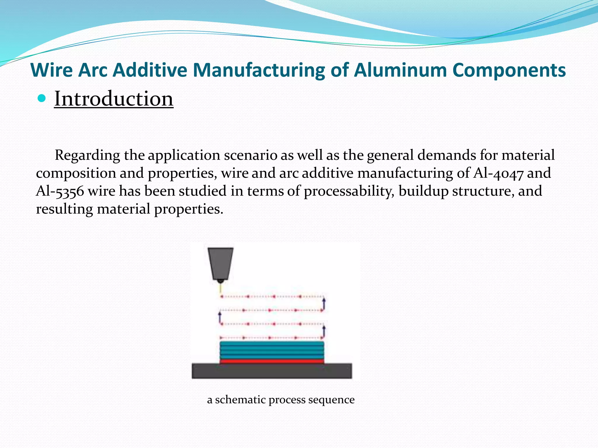
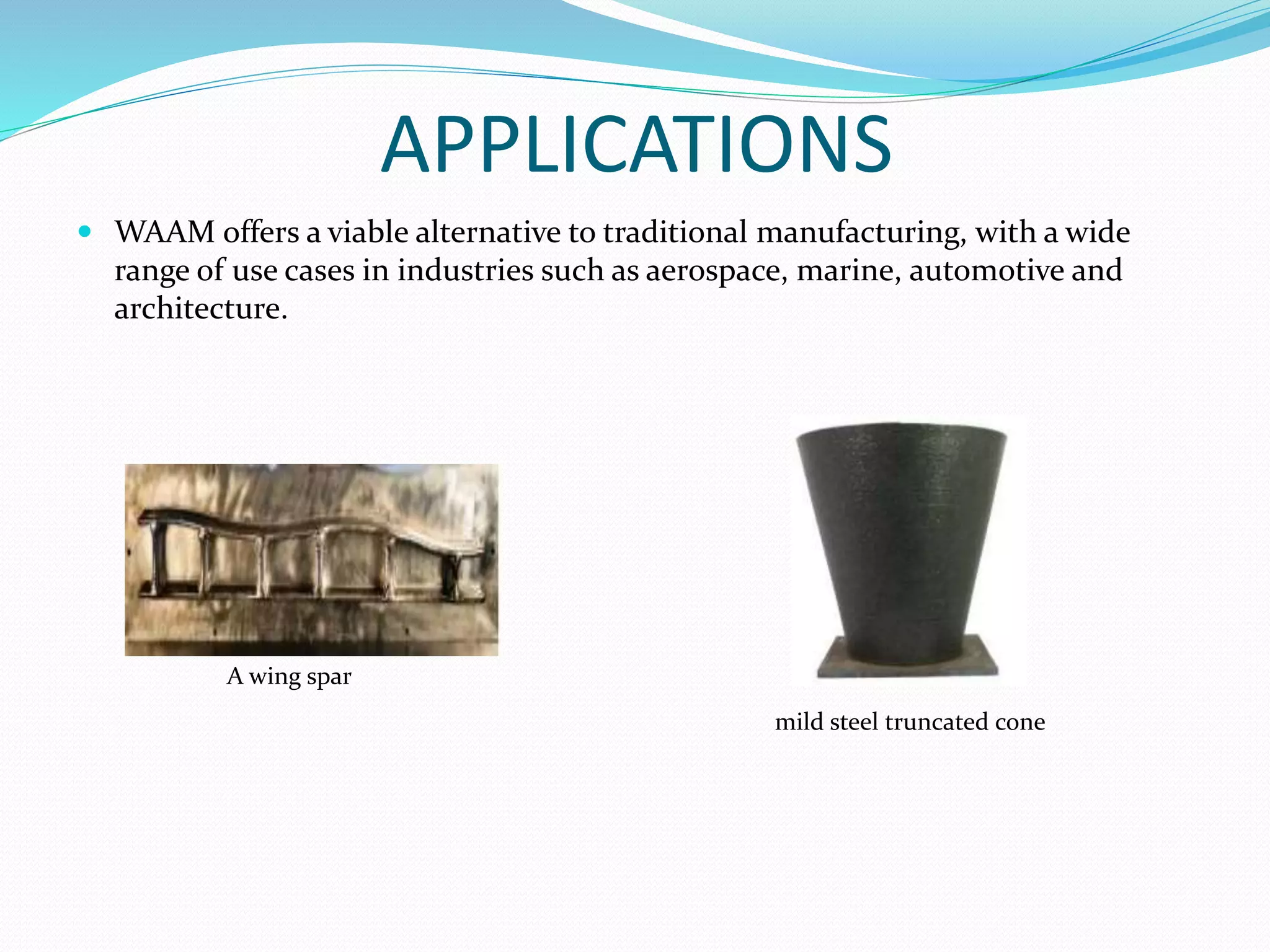
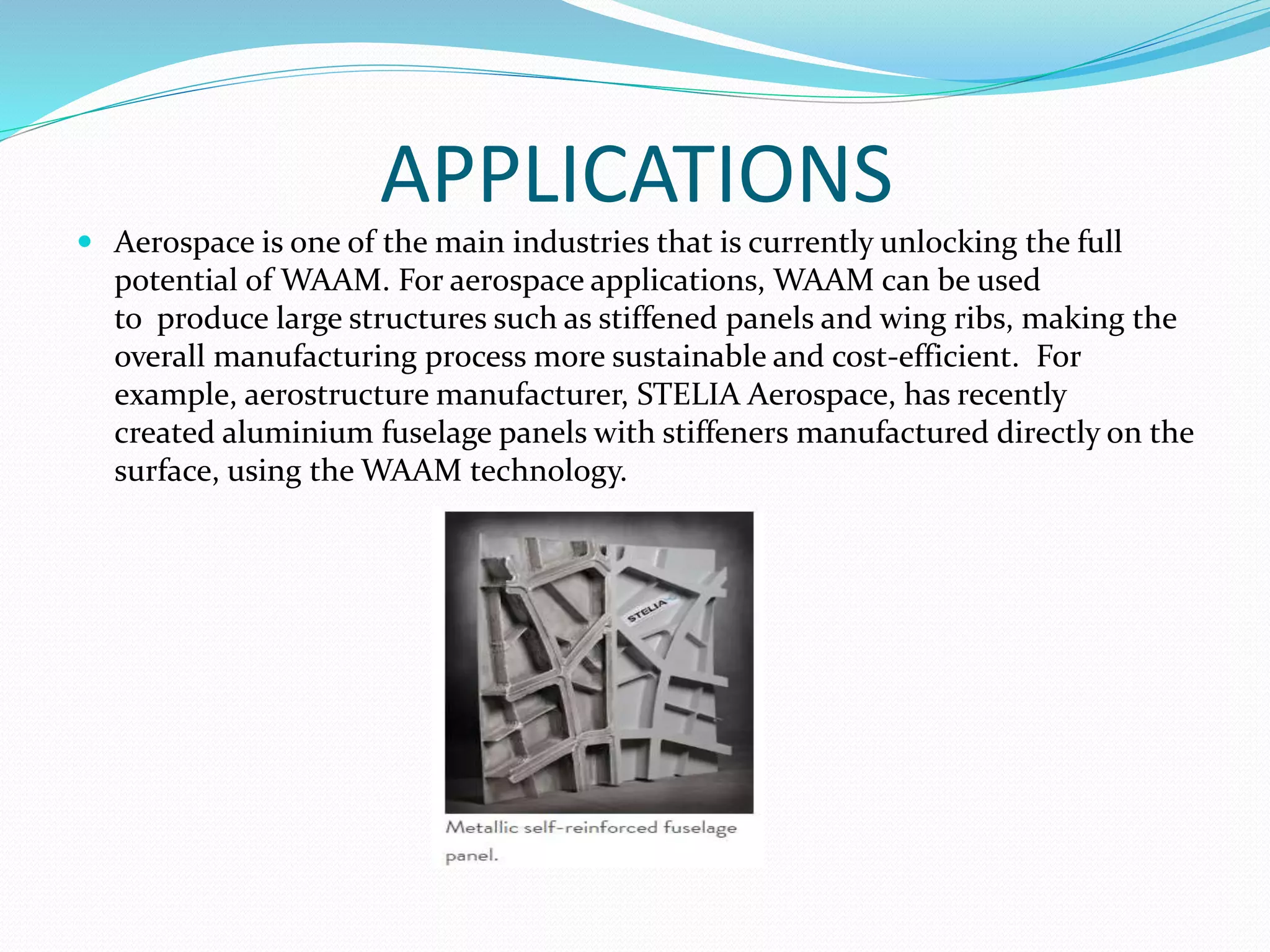
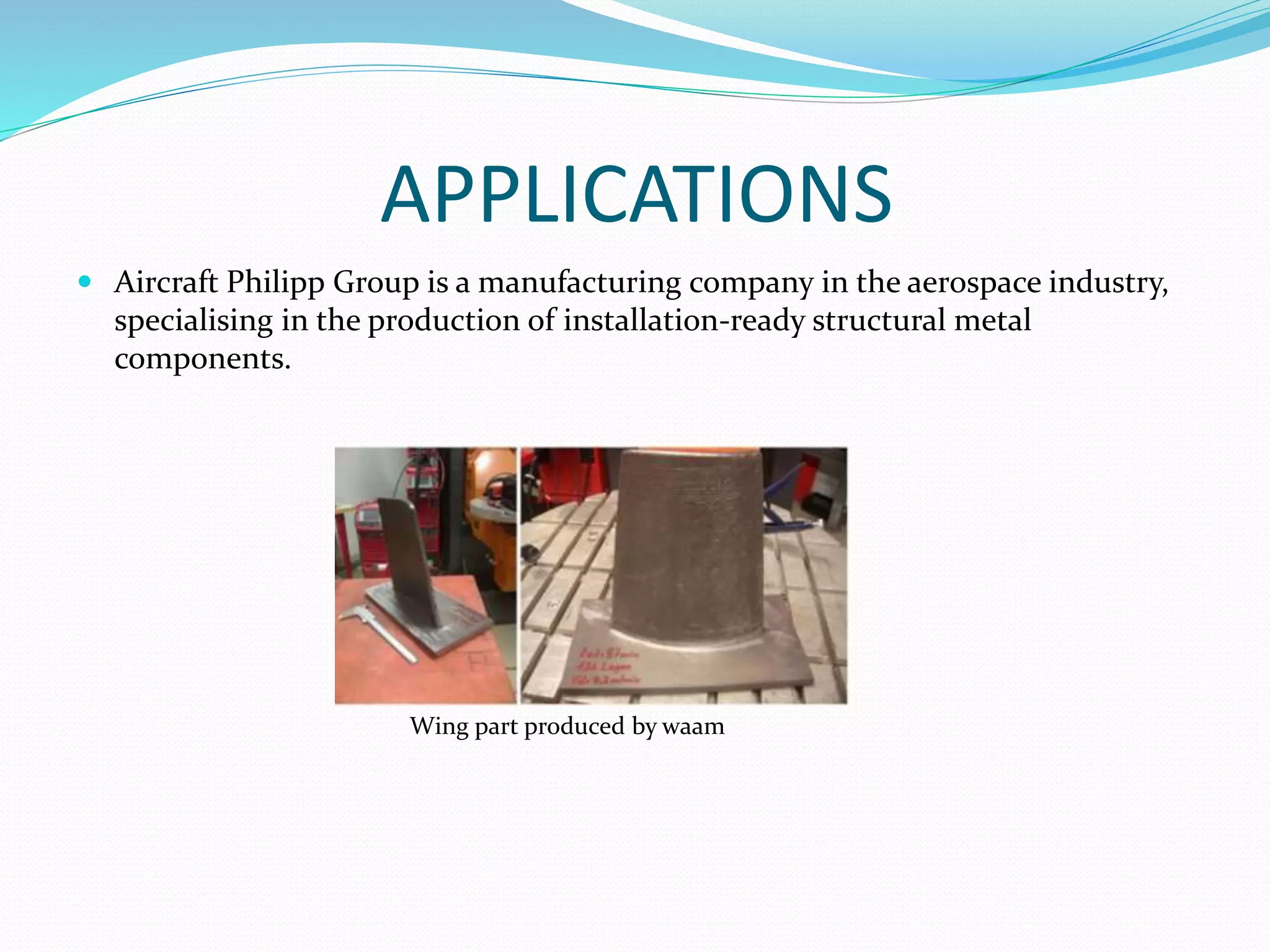
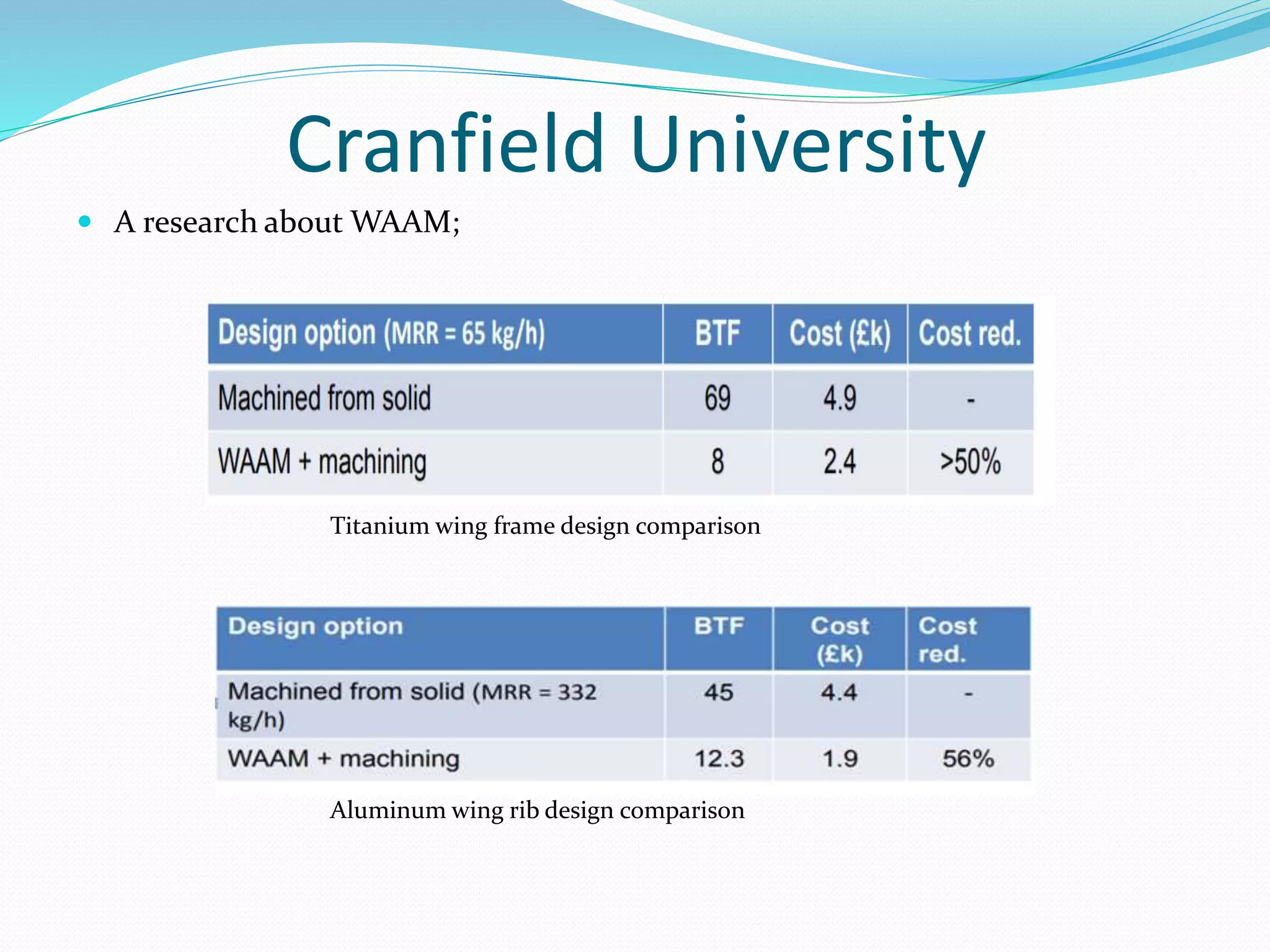
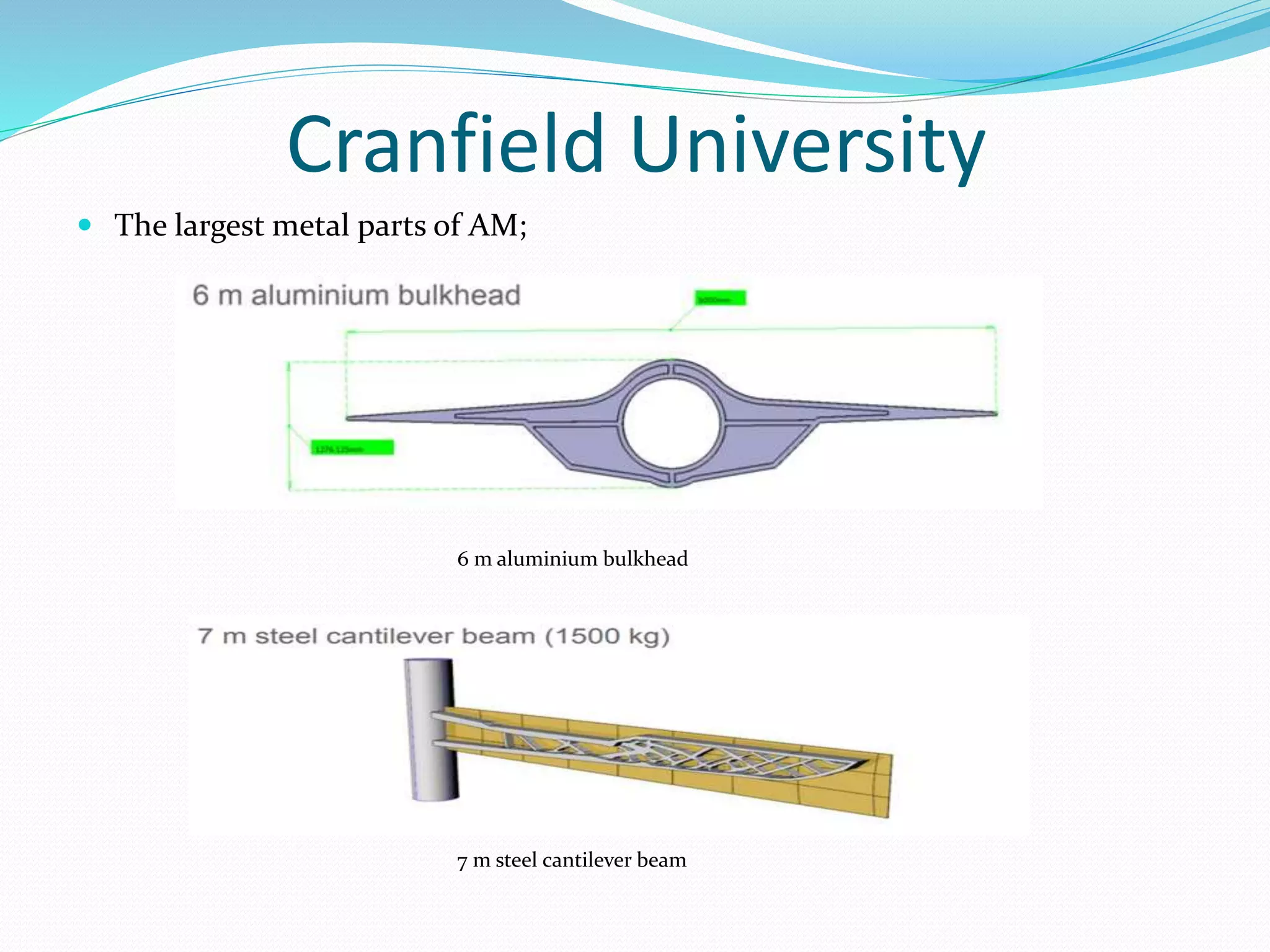
SPECIAL METAL MATERIALS AND INNOVATIVE
PROCESS TECHNOLOGIES UNIT
WIRE ARC ADDITIVE MANUFACTURING(WAAM)
CONTENTS
 ADDITIVE MANUFACTURING(AM)
 WIRE ARC ADDITIVE MANUFACTURING(WAAM)
 WIRE ARC ADDITIVE MANUFACTURING OF
ALUMINUM COMPONENTS
 APPLICATIONS OF WAAM
 SOME RESEARCHS of CRANFIELD UNIVERSITY
 WAAM vs POWDER LASER MELTING
Additive Manufacturing(AM)
 Additive Manufacturing (AM) is a technique where structures are produced by
ading and depositing material in a layer upon layer manner. Rather than
removing materials, AM processes make three-dimensional parts directly from
CAD models by adding materials layer by layer, offering the beneficial ability to
build parts with geometric and material complexities.
 Flow Chart of the Additive Manufacturing Process
Metallic Additive Manufacturing Systems
 AM system may be classified/categorized in terms of the material feed stock,
energy source, build volume.
 Powder Bed Systems:
The energy source (electron beam or laser beam) is programmed to
deliver energy to the surface of the bed melting or sintering the powder into the
desired shape. The advantages of this system include its ability to produce high
resolution features, internal passages, and maintain dimensional control.
Generic illustration of an AM powder bed system
Metallic Additive Manufacturing Systems
• Powder Feed Systems:
The build volumes of these systems are generally larger. A laser is used to
melt a monolayer or more of the powder into the shape desired. The advantages of
this type of system include its larger build volume and its ability to be used to
refurbish worn or damaged components.
Generic illustration of an AM powder feed system
Metallic Additive Manufacturing Systems
 Wire Feed Systems:
The feed stock is wire, and the energy source for these units can include
electron beam, laser beam, and plasma arc. In general, wire feed systems are well
suited for high deposition rate processing and have large build volumes; however,
the fabricated product usually requires more extensive machining than the
powder bed or powder fed systems do.
Generic illustration of an AM wire feed system
Wire Arc Additive Manufacturing(WAAM)
 WAAM is a technology which has been investigated in last 30 years.It became
interesting for scientists and manufacturers due to its ability to produce fully
dense metal parts and large near-netshape products.
A simple Waam system
Wire Arc Additive Manufacturing(WAAM)
 WAAM is mostly used in modern industries, like aerospace industry. It uses
existing welding equipment, electric arc as energy source and welding wire as
feedstock. Because of this, it is cheaper than other AM technologies, which
usually need specific equipment and materials.
Waam sample schema
Wire Arc Additive Manufacturing(WAAM)
 While the material deposition rate is 2-10 g/min in laser-based methods, the
material deposition rate reaches 50-130 g/min in the WAAM method. In
addition, WAAM is less costly. Material handling efficiency reaches 100% in
terms of wire material deposited on the part.
Landing gear component
Wire Arc Additive Manufacturing(WAAM)
Wire Arc Additive Manufacturing of Aluminum Components
 Introduction
Regarding the application scenario as well as the general demands for material
composition and properties, wire and arc additive manufacturing of Al-4047 and
Al-5356 wire has been studied in terms of processability, buildup structure, and
resulting material properties.
a schematic process sequence
Wire Arc Additive Manufacturing of Aluminum Components
 Materials and Methods
Experiments were carried out on Al-6082 substrates with dimensions 150 mm
× 40 mm × 10 mm. For deposition, a solid wire electrode with a diameter of 1.0
mm was used. Metallographic samples were taken from the middle part of the
samples for macrostructure analysis. Tensile test was conducted at room
temperature with a test speed of 3.2 mm/min.
Nominal composition of welding wires
Welding parameters used for sample processing
Wire Arc Additive Manufacturing of Aluminum Components
 Results and Discussion
The results from visual examination indicated a more uneven geometry
formation with higher waviness using Al-4047.
The samples using Al-5356 showed a smooth and uniform wall surface.
The low energy input (current / voltage) does not alter the geometric
accuracy of the wall structure.
Manufactured Al-4047 sample Manufactured Al-5356 sample
Wire Arc Additive Manufacturing of Aluminum Components
 Results and Discussion
As shown in Figure, no significant change in hardness values can be
detected along the buildup of Al-5356.
Hardness values of Al-4047 showed an inhomogeneous profile.
hardness distribution depending on buildup height
Wire Arc Additive Manufacturing of Aluminum Components
 Conclusion
According to the analysis results;
•A wide solidification range is more suitable for uniform deposition.
• Increased arc length result in higher dynamic forces , thus affecting
deposition accuracy.
• Material properties are evenly distributed over the buildup geometry
when the interpass temperature is kept constant.
• Residual stress magnitude depends on yield strength of the filler
material.
A modular path planning solution for Wire + Arc Additive
Manufacturing
Accurate path planning is as important as selecting the optimum process
parameters.
Figure10. Sharped turn(a) vs corner division (b).
Figure11. Path generetion through width varition.
If curved trajectories can be deposited,
sharp turns should be avoided, and instead
replaced by corner intersections (Fig. 4).
Similarly, if a slight width variation does not
alter the deposition (Fig. 5a), an abrupt
width variation can create irregular paths
(Fig. 5b) leading, layer after layer, to
significant defects. Therefore, to avoid those
irregularities, it is preferred to divide this
part in multiple sections (Fig. 5c)
A modular path planning solution for Wire + Arc Additive
Manufacturing
 As it can be seen in Fig. 7a, a simple straight wall contains three zones to
accommodate the different thermal conditions in the stages of deposition start,
steady state, and end. This must be done whichever path is used: single bead,
oscillated or parallel. Additionally, if a section contains a notable width
variation requiring specific deposition parameters, a zone can be defined to
account for that change in width, and to manually adapt the parameters locally
(Fig. 7b). Finally, because the heat dissipation is drastically different at the
intersections, it is crucial to create zones at those locations (Fig. 7c).
Figure12. Zones definition.
APPLICATIONS
 WAAM offers a viable alternative to traditional manufacturing, with a wide
range of use cases in industries such as aerospace, marine, automotive and
architecture.
A wing spar
mild steel truncated cone
APPLICATIONS
 Aerospace is one of the main industries that is currently unlocking the full
potential of WAAM. For aerospace applications, WAAM can be used
to produce large structures such as stiffened panels and wing ribs, making the
overall manufacturing process more sustainable and cost-efficient. For
example, aerostructure manufacturer, STELIA Aerospace, has recently
created aluminium fuselage panels with stiffeners manufactured directly on the
surface, using the WAAM technology.
APPLICATIONS
 Aircraft Philipp Group is a manufacturing company in the aerospace industry,
specialising in the production of installation-ready structural metal
components.
Wing part produced by waam
Cranfield University
 What they’ve deposited so far;
 Ti-6Al-4V Aluminium Refractories
– Grade 5 – 2024 –Tungsten
– Grade 23 – 2319 –Molybdenum
– 4043 –Tantalum
Steels Inconel Bronze Copper
– Stainless (17-4 PH, 316L) – 625
– 718
Cranfield University
 A research about WAAM;
Titanium wing frame design comparison
Aluminum wing rib design comparison
Cranfield University
 The largest metal parts of AM;
6 m aluminium bulkhead
7 m steel cantilever beam
WAAM vs Powder Laser Melting
 The Waam method has the potential to produce large-scale metallic parts at
the highest level due to its high deposition rate, low equipment investment and
low operating costs.
 Waam materials generally exhibit better mechanical properties than their
counterparts, and also do not exhibit high levels of porosity, which reduces
fatigue life, as in the case of powder bed melting.
 However,, geometrical and surface accuracy are lower compared to powder-
based processes.
Comparison of AM methods.
REFERENCES
 An Introduction to Wire Arc Additive Manufacturing. (2018, June 14). Retrieved from
https://amfg.ai/2018/05/17/an-introduction-to-wire-arc-additive-manufacturing/
 WAAM - Wire Arc Additive Manufacturing. (n.d.). Retrieved from https://www.aircraft-
philipp.com/en/acp-additive-manufacturing/waam-wire-arc-additive-manufacturing/
 Williams, S. W., Martina, F., Addison, A. C., Ding, J., Pardal, G., & Colegrove, P. (2016). Wire Arc
Additive Manufacturing. Material Science and Technology, 32(7), 641-647.
 WAAMMat. (n.d.). Retrieved from https://waammat.com/
 Ayan, Y., & Kahraman, N. (2018). METAL EKLEMELİ İMALAT: TEL ARK YÖNTEMİ VE
UYGULAMALARI. INTERNATIONAL JOURNAL OF 3D PRINTING TECHNOLOGIES AND DIGITAL
INDUSTRY, 2(3), 78-84.
 Guo, N. & Leu, M.C. Front. Mech. Eng. (2013) 8: 215. https://doi.org/10.1007/s11465-013-0248-8
 Frazier, W.E. J. of Materi Eng and Perform (2014) 23: 1917. https://doi.org/10.1007/s11665-014-0958-z
 Köhler, M., Fiebig, S., Hensel, J., & Dilger, K. (2019). Wire and Arc Additive Manufacturing of
Aluminum Components. Metals, 9(608). doi::10.3390/met9050608
THANKS FOR YOUR ATTENTION

Wire Arc Additive Manufacturing

  • 1.
    SPECIAL METAL MATERIALSAND INNOVATIVE PROCESS TECHNOLOGIES UNIT WIRE ARC ADDITIVE MANUFACTURING(WAAM)
  • 2.
    CONTENTS  ADDITIVE MANUFACTURING(AM) WIRE ARC ADDITIVE MANUFACTURING(WAAM)  WIRE ARC ADDITIVE MANUFACTURING OF ALUMINUM COMPONENTS  APPLICATIONS OF WAAM  SOME RESEARCHS of CRANFIELD UNIVERSITY  WAAM vs POWDER LASER MELTING
  • 3.
    Additive Manufacturing(AM)  AdditiveManufacturing (AM) is a technique where structures are produced by ading and depositing material in a layer upon layer manner. Rather than removing materials, AM processes make three-dimensional parts directly from CAD models by adding materials layer by layer, offering the beneficial ability to build parts with geometric and material complexities.  Flow Chart of the Additive Manufacturing Process
  • 4.
    Metallic Additive ManufacturingSystems  AM system may be classified/categorized in terms of the material feed stock, energy source, build volume.  Powder Bed Systems: The energy source (electron beam or laser beam) is programmed to deliver energy to the surface of the bed melting or sintering the powder into the desired shape. The advantages of this system include its ability to produce high resolution features, internal passages, and maintain dimensional control. Generic illustration of an AM powder bed system
  • 5.
    Metallic Additive ManufacturingSystems • Powder Feed Systems: The build volumes of these systems are generally larger. A laser is used to melt a monolayer or more of the powder into the shape desired. The advantages of this type of system include its larger build volume and its ability to be used to refurbish worn or damaged components. Generic illustration of an AM powder feed system
  • 6.
    Metallic Additive ManufacturingSystems  Wire Feed Systems: The feed stock is wire, and the energy source for these units can include electron beam, laser beam, and plasma arc. In general, wire feed systems are well suited for high deposition rate processing and have large build volumes; however, the fabricated product usually requires more extensive machining than the powder bed or powder fed systems do. Generic illustration of an AM wire feed system
  • 7.
    Wire Arc AdditiveManufacturing(WAAM)  WAAM is a technology which has been investigated in last 30 years.It became interesting for scientists and manufacturers due to its ability to produce fully dense metal parts and large near-netshape products. A simple Waam system
  • 8.
    Wire Arc AdditiveManufacturing(WAAM)  WAAM is mostly used in modern industries, like aerospace industry. It uses existing welding equipment, electric arc as energy source and welding wire as feedstock. Because of this, it is cheaper than other AM technologies, which usually need specific equipment and materials. Waam sample schema
  • 9.
    Wire Arc AdditiveManufacturing(WAAM)  While the material deposition rate is 2-10 g/min in laser-based methods, the material deposition rate reaches 50-130 g/min in the WAAM method. In addition, WAAM is less costly. Material handling efficiency reaches 100% in terms of wire material deposited on the part. Landing gear component
  • 10.
    Wire Arc AdditiveManufacturing(WAAM)
  • 11.
    Wire Arc AdditiveManufacturing of Aluminum Components  Introduction Regarding the application scenario as well as the general demands for material composition and properties, wire and arc additive manufacturing of Al-4047 and Al-5356 wire has been studied in terms of processability, buildup structure, and resulting material properties. a schematic process sequence
  • 12.
    Wire Arc AdditiveManufacturing of Aluminum Components  Materials and Methods Experiments were carried out on Al-6082 substrates with dimensions 150 mm × 40 mm × 10 mm. For deposition, a solid wire electrode with a diameter of 1.0 mm was used. Metallographic samples were taken from the middle part of the samples for macrostructure analysis. Tensile test was conducted at room temperature with a test speed of 3.2 mm/min. Nominal composition of welding wires Welding parameters used for sample processing
  • 13.
    Wire Arc AdditiveManufacturing of Aluminum Components  Results and Discussion The results from visual examination indicated a more uneven geometry formation with higher waviness using Al-4047. The samples using Al-5356 showed a smooth and uniform wall surface. The low energy input (current / voltage) does not alter the geometric accuracy of the wall structure. Manufactured Al-4047 sample Manufactured Al-5356 sample
  • 14.
    Wire Arc AdditiveManufacturing of Aluminum Components  Results and Discussion As shown in Figure, no significant change in hardness values can be detected along the buildup of Al-5356. Hardness values of Al-4047 showed an inhomogeneous profile. hardness distribution depending on buildup height
  • 15.
    Wire Arc AdditiveManufacturing of Aluminum Components  Conclusion According to the analysis results; •A wide solidification range is more suitable for uniform deposition. • Increased arc length result in higher dynamic forces , thus affecting deposition accuracy. • Material properties are evenly distributed over the buildup geometry when the interpass temperature is kept constant. • Residual stress magnitude depends on yield strength of the filler material.
  • 16.
    A modular pathplanning solution for Wire + Arc Additive Manufacturing Accurate path planning is as important as selecting the optimum process parameters. Figure10. Sharped turn(a) vs corner division (b). Figure11. Path generetion through width varition. If curved trajectories can be deposited, sharp turns should be avoided, and instead replaced by corner intersections (Fig. 4). Similarly, if a slight width variation does not alter the deposition (Fig. 5a), an abrupt width variation can create irregular paths (Fig. 5b) leading, layer after layer, to significant defects. Therefore, to avoid those irregularities, it is preferred to divide this part in multiple sections (Fig. 5c)
  • 17.
    A modular pathplanning solution for Wire + Arc Additive Manufacturing  As it can be seen in Fig. 7a, a simple straight wall contains three zones to accommodate the different thermal conditions in the stages of deposition start, steady state, and end. This must be done whichever path is used: single bead, oscillated or parallel. Additionally, if a section contains a notable width variation requiring specific deposition parameters, a zone can be defined to account for that change in width, and to manually adapt the parameters locally (Fig. 7b). Finally, because the heat dissipation is drastically different at the intersections, it is crucial to create zones at those locations (Fig. 7c). Figure12. Zones definition.
  • 18.
    APPLICATIONS  WAAM offersa viable alternative to traditional manufacturing, with a wide range of use cases in industries such as aerospace, marine, automotive and architecture. A wing spar mild steel truncated cone
  • 19.
    APPLICATIONS  Aerospace isone of the main industries that is currently unlocking the full potential of WAAM. For aerospace applications, WAAM can be used to produce large structures such as stiffened panels and wing ribs, making the overall manufacturing process more sustainable and cost-efficient. For example, aerostructure manufacturer, STELIA Aerospace, has recently created aluminium fuselage panels with stiffeners manufactured directly on the surface, using the WAAM technology.
  • 20.
    APPLICATIONS  Aircraft PhilippGroup is a manufacturing company in the aerospace industry, specialising in the production of installation-ready structural metal components. Wing part produced by waam
  • 21.
    Cranfield University  Whatthey’ve deposited so far;  Ti-6Al-4V Aluminium Refractories – Grade 5 – 2024 –Tungsten – Grade 23 – 2319 –Molybdenum – 4043 –Tantalum Steels Inconel Bronze Copper – Stainless (17-4 PH, 316L) – 625 – 718
  • 22.
    Cranfield University  Aresearch about WAAM; Titanium wing frame design comparison Aluminum wing rib design comparison
  • 23.
    Cranfield University  Thelargest metal parts of AM; 6 m aluminium bulkhead 7 m steel cantilever beam
  • 24.
    WAAM vs PowderLaser Melting  The Waam method has the potential to produce large-scale metallic parts at the highest level due to its high deposition rate, low equipment investment and low operating costs.  Waam materials generally exhibit better mechanical properties than their counterparts, and also do not exhibit high levels of porosity, which reduces fatigue life, as in the case of powder bed melting.  However,, geometrical and surface accuracy are lower compared to powder- based processes. Comparison of AM methods.
  • 25.
    REFERENCES  An Introductionto Wire Arc Additive Manufacturing. (2018, June 14). Retrieved from https://amfg.ai/2018/05/17/an-introduction-to-wire-arc-additive-manufacturing/  WAAM - Wire Arc Additive Manufacturing. (n.d.). Retrieved from https://www.aircraft- philipp.com/en/acp-additive-manufacturing/waam-wire-arc-additive-manufacturing/  Williams, S. W., Martina, F., Addison, A. C., Ding, J., Pardal, G., & Colegrove, P. (2016). Wire Arc Additive Manufacturing. Material Science and Technology, 32(7), 641-647.  WAAMMat. (n.d.). Retrieved from https://waammat.com/  Ayan, Y., & Kahraman, N. (2018). METAL EKLEMELİ İMALAT: TEL ARK YÖNTEMİ VE UYGULAMALARI. INTERNATIONAL JOURNAL OF 3D PRINTING TECHNOLOGIES AND DIGITAL INDUSTRY, 2(3), 78-84.  Guo, N. & Leu, M.C. Front. Mech. Eng. (2013) 8: 215. https://doi.org/10.1007/s11465-013-0248-8  Frazier, W.E. J. of Materi Eng and Perform (2014) 23: 1917. https://doi.org/10.1007/s11665-014-0958-z  Köhler, M., Fiebig, S., Hensel, J., & Dilger, K. (2019). Wire and Arc Additive Manufacturing of Aluminum Components. Metals, 9(608). doi::10.3390/met9050608
  • 26.
    THANKS FOR YOURATTENTION