1. Rapid prototyping is a group of techniques that quickly fabricate a scale model of a physical part using 3D computer-aided design data through additive layer manufacturing. 2. The document discusses the history and development of rapid prototyping technologies from the 1980s onward. 3. It describes common rapid prototyping processes like stereolithography, selective laser sintering, and fused deposition modeling which build parts layer-by-layer from materials in different states of matter.
![2
Seminar Report 2015 Rapid Prototyping
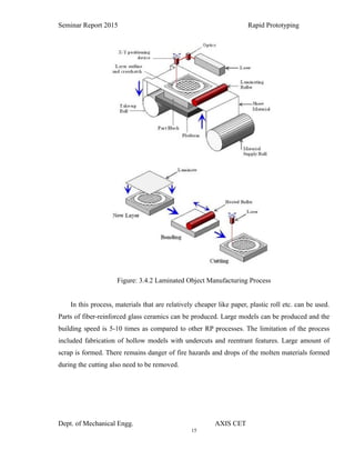
2. Design for Rapid Manufacture
3. Organization and Implementation
UK funded research projects in all these areas have commenced within the RMRG and this
paper discusses some results of work into the design optimization and customization aspects that
are enabled by RM. The results are derived from the ‘Design for Rapid Manufacture’ and
‘Management, Organizational and Implementation of Rapid Manufacturing’ (Man RM) projects.
It should be noted that although the Man RM project is principally concerned with the
management implications of RM, much work has also been carried out into what is becoming a
significantly important area for business – the area of customization and personalization of
products. It should be noted that an assumption on the projects has been made that the viable
Rapid Manufacturing process have been developed that additively produce end-use parts in
suitable materials and with acceptable surface finish, accuracy and speed.
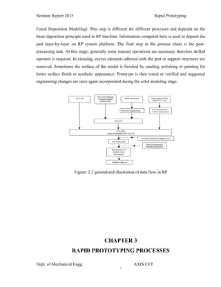
As with CNC subtractive methods, the CAD-CAM workflow in the traditional Rapid
Prototyping process starts with the creation of geometric data, either as a 3D solid using
a CAD workstation, or 2D slices using a scanning device. For RP this data must represent a valid
geometric model; namely, one whose boundary surfaces enclose a finite volume, contains no
holes exposing the interior, and do not fold back on themselves. In other words, the object must
have an inside. The model is valid if for each point in 3D space the computer can determine
uniquely whether that point lies inside, on, or outside the boundary surface of the
model. CAD post-processors will approximate the application vendors’ internal CAD geometric
forms (e.g., B-spines) with a simplified mathematical form, which in turn is expressed in a
specified data format which is a common feature in Additive Manufacturing: STL
(stereolithography) a de facto standard for transferring solid geometric models to SFF machines.
To obtain the necessary motion control trajectories to drive the actual SFF, Rapid
Prototyping, 3D Printing or Additive Manufacturing mechanism, the prepared geometric model
is typically sliced into layers, and the slices are scanned into lines [producing a "2D drawing"
used to generate trajectory as in CNC`s tool path], mimicking in reverse the layer-to-layer
physical building process.
1.1 HISTORY
Dept. of Mechanical Engg. AXIS CET](https://image.slidesharecdn.com/rapidprototypiung-150806084332-lva1-app6892/85/Rapid-prototyping-2-320.jpg)
![3
Seminar Report 2015 Rapid Prototyping
In the 1980s U.S. policy makers and industrial managers were forced to take note that
America's dominance in the field of machine tool manufacturing evaporated, in what was named
the machine tool crisis. Numerous projects sought to counter these trends in the
traditional CNC CAM area, which had begun in the US. Later when Rapid Prototyping Systems
moved out of labs to be commercialized it was recognized that developments were already
international and U.S. rapid prototyping companies would not have the luxury of letting a lead
slip away. The National Science Foundation was an umbrella for the National Aeronautics and
Space Administration (NASA), the US Department of Energy, the US Department of
Commerce NIST, the US Department of Defense, Defense Advanced Research Projects
Agency (DARPA), and the Office of Naval Research coordinated studies to inform strategic
planners in their deliberations. One such report was the 1997 Rapid Prototyping in Europe and
Japan Panel Report in which Joseph J. Beaman founder of DTM Corporation DTM RapidTool
pictured] provides a historical perspective: The roots of rapid prototyping technology can be
traced to practices in topography and photo sculpture. Within TOPOGRAPHY Blanther (1892)
suggested a layered method for making a mold for raised relief paper topographical maps .The
process involved cutting the contour lines on a series of plates which were then stacked.
Matsubara (1974) of Mitsubishi proposed a topographical process with a photo-
hardening photopolymer resin to form thin layers stacked to make a casting mold.
PHOTOSCULPTURE was a 19th-century technique to create exact three-dimensional replicas of
objects. Most famously Francois Willeme (1860) placed 24 cameras in a circular array and
simultaneously photographed an object. The silhouette of each photograph was then used to
carve a replica. Morioka (1935, 1944) developed a hybrid photo sculpture and topographic
process using structured light to photographically create contour lines of an object. The lines
could then be developed into sheets and cut and stacked, or projected onto stock material for
carving. The Munz (1956) Process reproduced a three-dimensional image of an object by
selectively exposing, layer by layer, a photo emulsion on a lowering piston. After fixing, a solid
transparent cylinder contains an image of the object.
The technologies referred to as Solid Freeform Fabrication are what we recognize today as
Rapid Prototyping, 3D Printing or Additive Manufacturing: Swainson (1977), Schwerzel (1984)
Dept. of Mechanical Engg. AXIS CET](https://image.slidesharecdn.com/rapidprototypiung-150806084332-lva1-app6892/85/Rapid-prototyping-3-320.jpg)
![18
Seminar Report 2015 Rapid Prototyping
optimisation techniques and then subsequently fabricated. However, this impossible to make due
to DFM criteria – this is one of the main stumbling blocks for so-called Knowledge Based
Engineering (KBE) systems that often have FEA as the kernel. The design optimisation is
followed by the application of industrial design to the FEA optimised product in order to produce
a hybrid design that encompasses both engineering and aesthetic aspects. This approach follows
the conclusions of a previous investigation for Custom Design Technologies (formerly Bafbox)
that was undertaken during the Design for RM research project [7]. During this work, it was
speculated that as DFM criteria are no longer valid with the advent of RM, then a hybrid design
methodology will emerge where the industrial designer would be able to manufacture any design
that they desire without the need to consider DFM. Thus, there would be an overriding need for
them to incorporate some engineering aspects in their product design. This investigation extends
this principle by incorporating design optimisation and aesthetic design in a single product
design methodology.
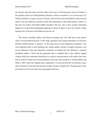
MG Rover is currently looking into ways to modularise their product range by modularizing the
components that go to make up different vehicle variants, thus reducing the costs of production
for those vehicles. One part of considerable interest to MG Rover was the development of a
modular handbrake. Currently an expensive metal stamped device is used and these components
are individual to each vehicle variant. In order to provide a more cost effective solution MG
Rover are investigating the use of an injection molded handbrake lever – with a metal ratchet
mechanism, that could be common across the vehicle range. As such, a handbrake lever from the
Rover 75 has been redesigned with injection moulding criteria in mind. As part of their
involvement in the Design for Rapid Manufacture project, MG Rover agreed to perform a
concurrent study to investigate how the design of the handbrake lever would change with the
advent of Rapid Manufacturing with an emphasis on material minimisation. It was a requirement
of the RM designed lever to fit to the ratchet mechanism that had previously been developed for
the injection-molded handbrake.
4.1.4 DESIGN CUSTOMISATION
One area where Rapid Manufacturing could have a significant impact on both customers and
Dept. of Mechanical Engg. AXIS CET](https://image.slidesharecdn.com/rapidprototypiung-150806084332-lva1-app6892/85/Rapid-prototyping-18-320.jpg)


![5G Explained! A High Level Overview [Introduction]](https://cdn.slidesharecdn.com/ss_thumbnails/5gexplainedahighleveloverview-260119165306-cc137a3e-thumbnail.jpg?width=640&height=640&fit=bounds)


