Downloaded 185 times
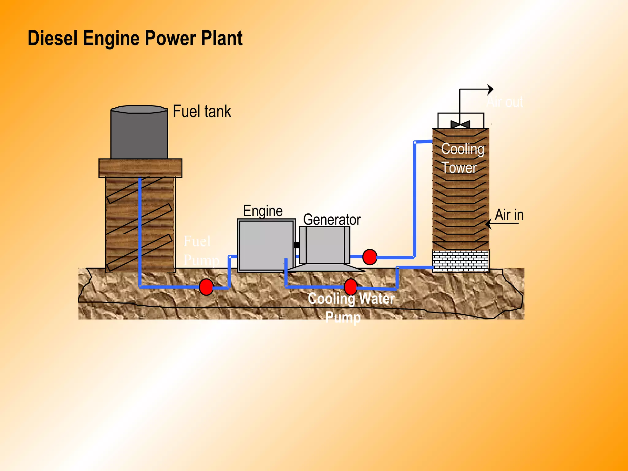
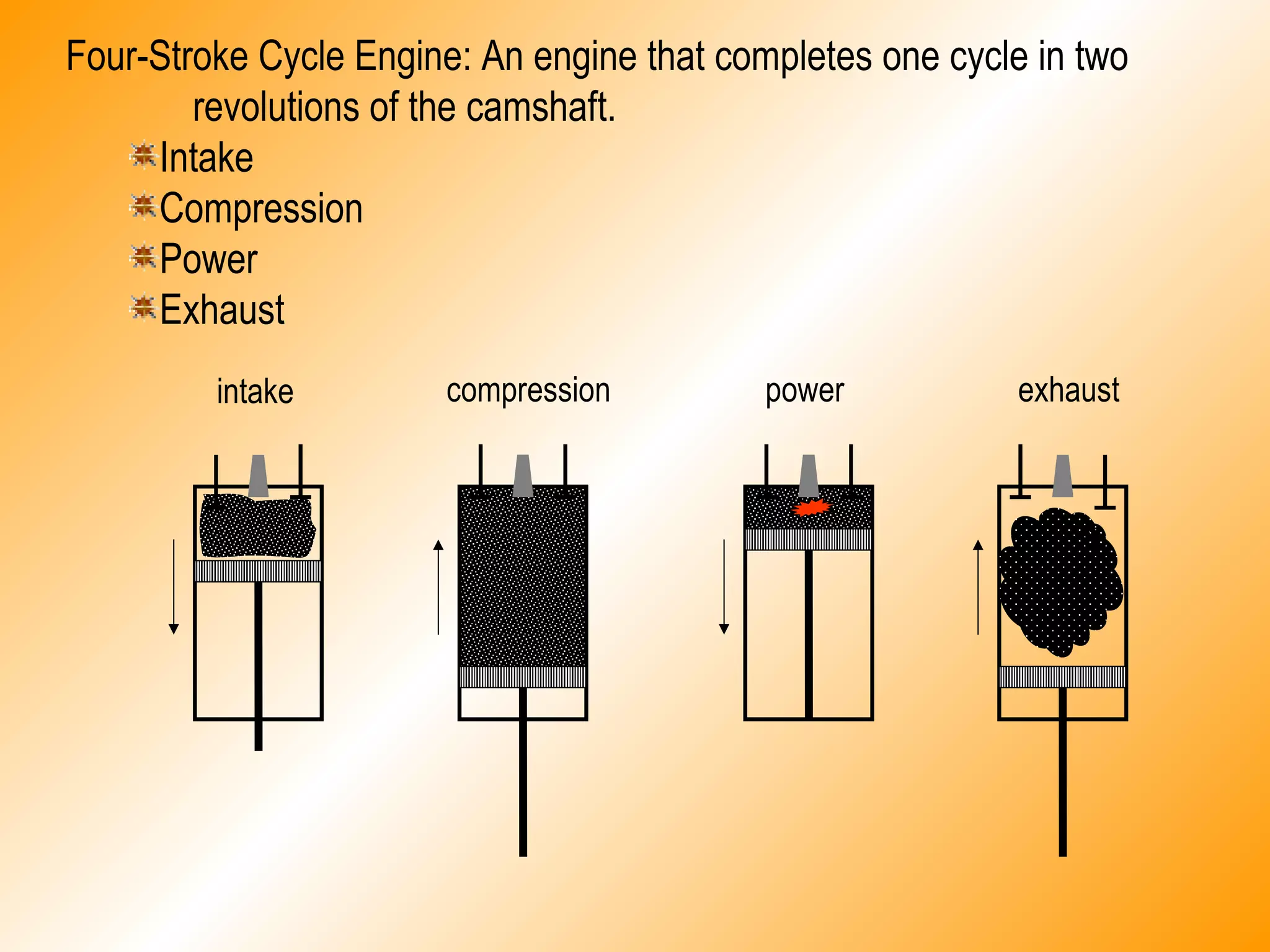
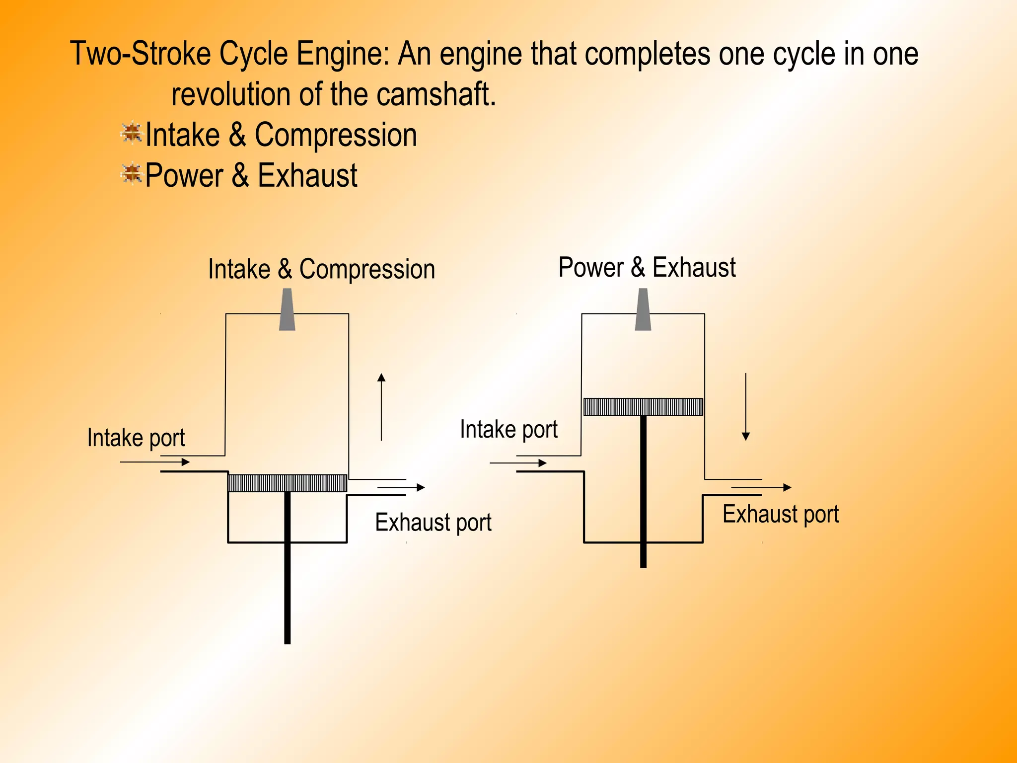
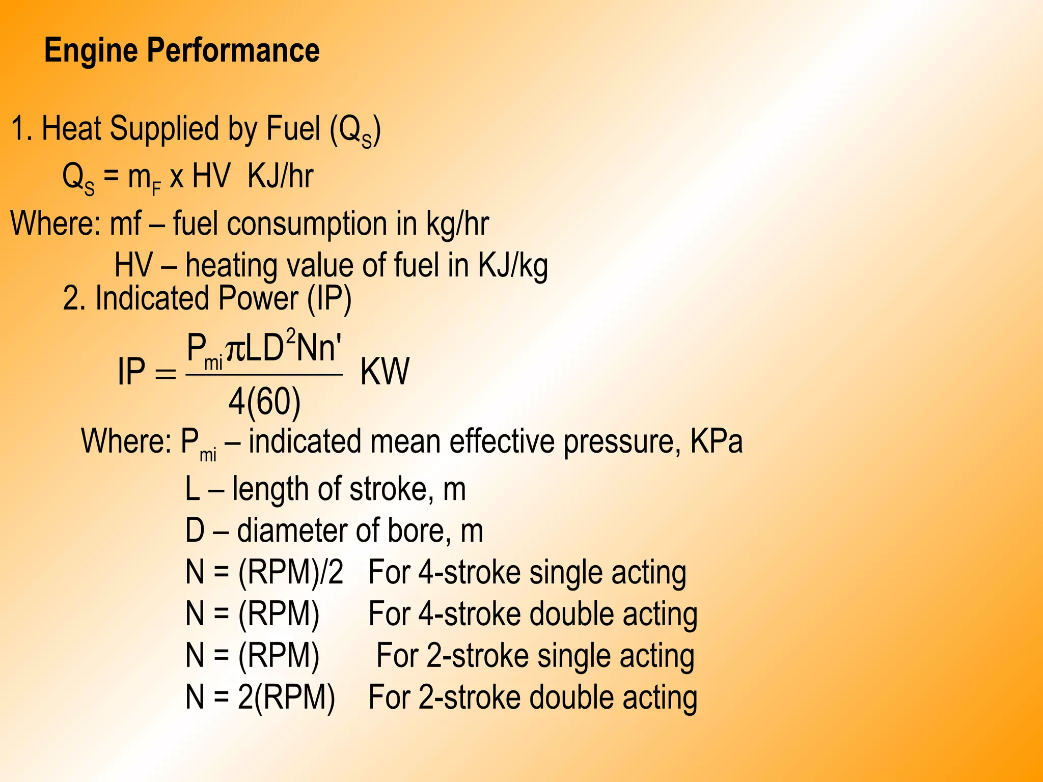
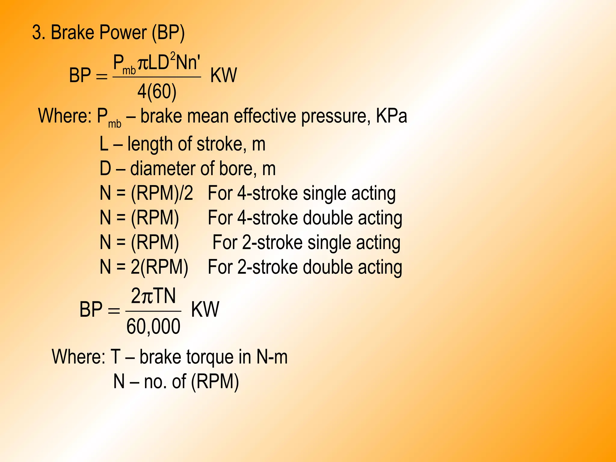
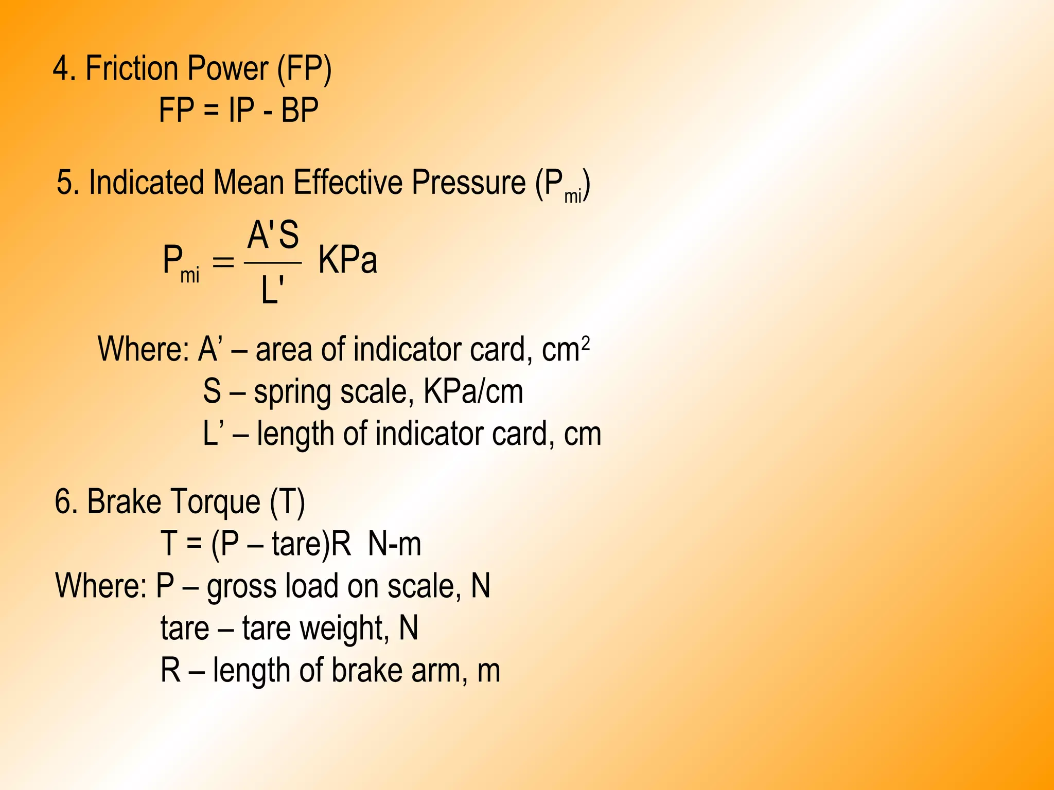
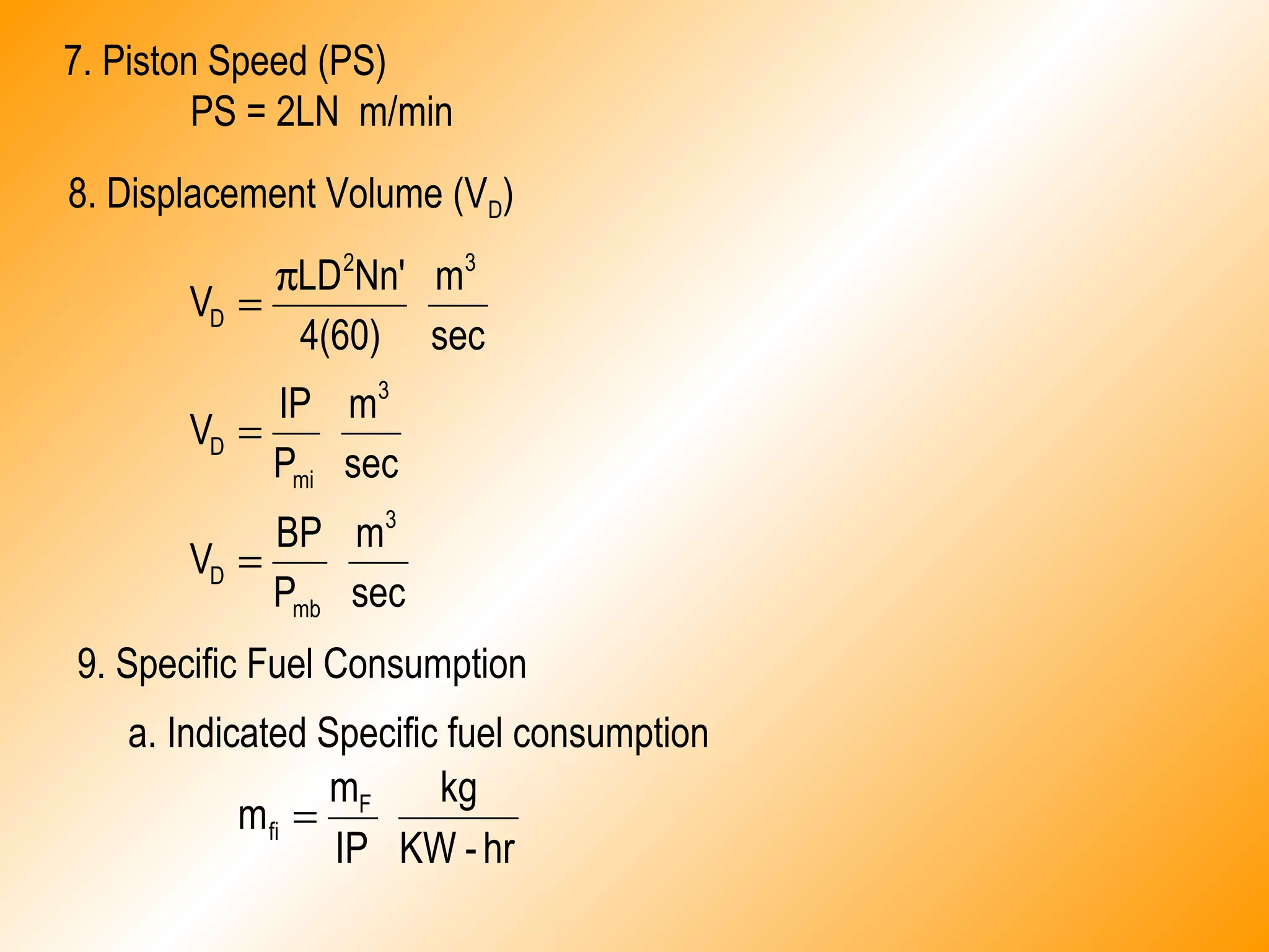
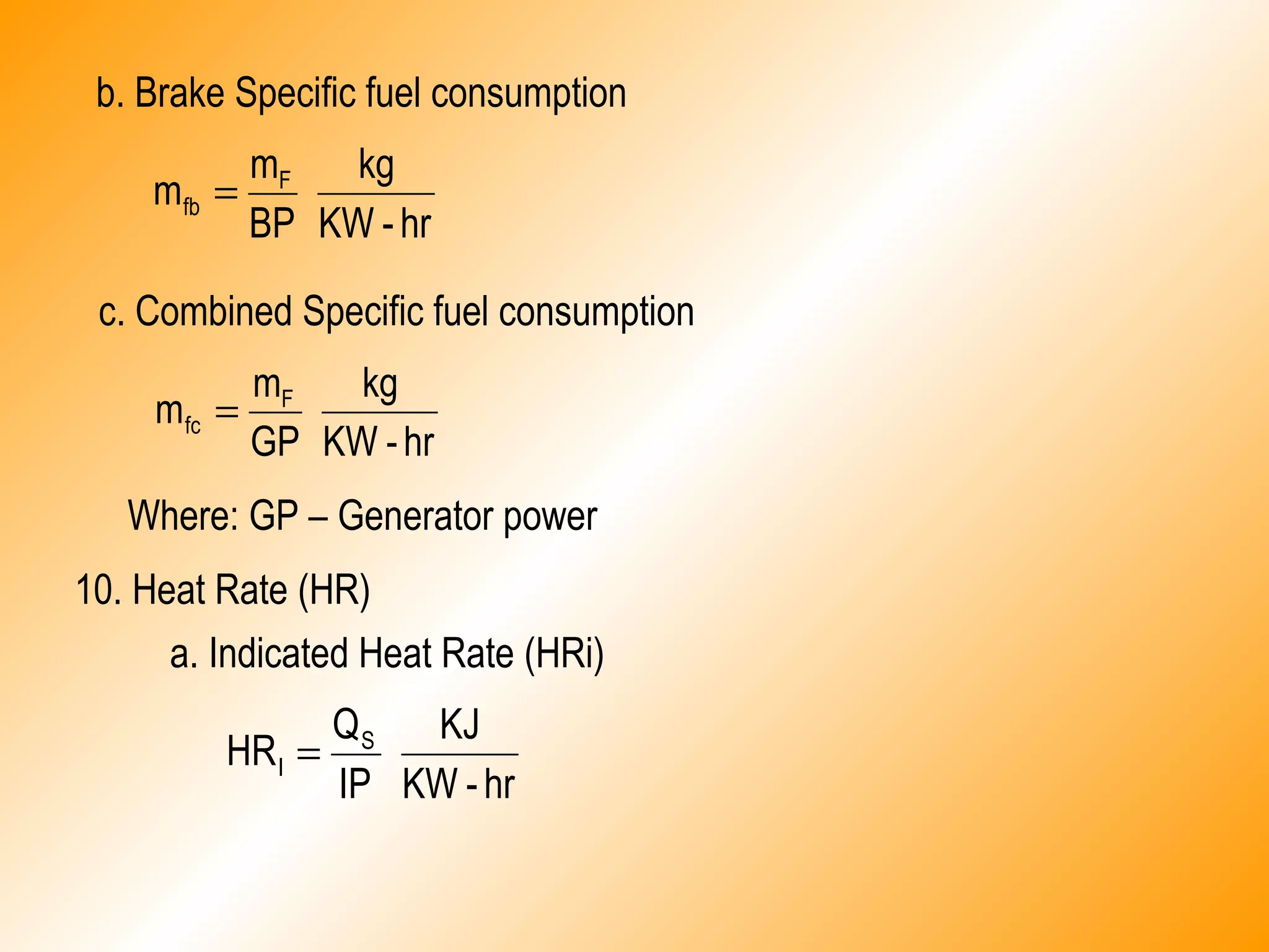
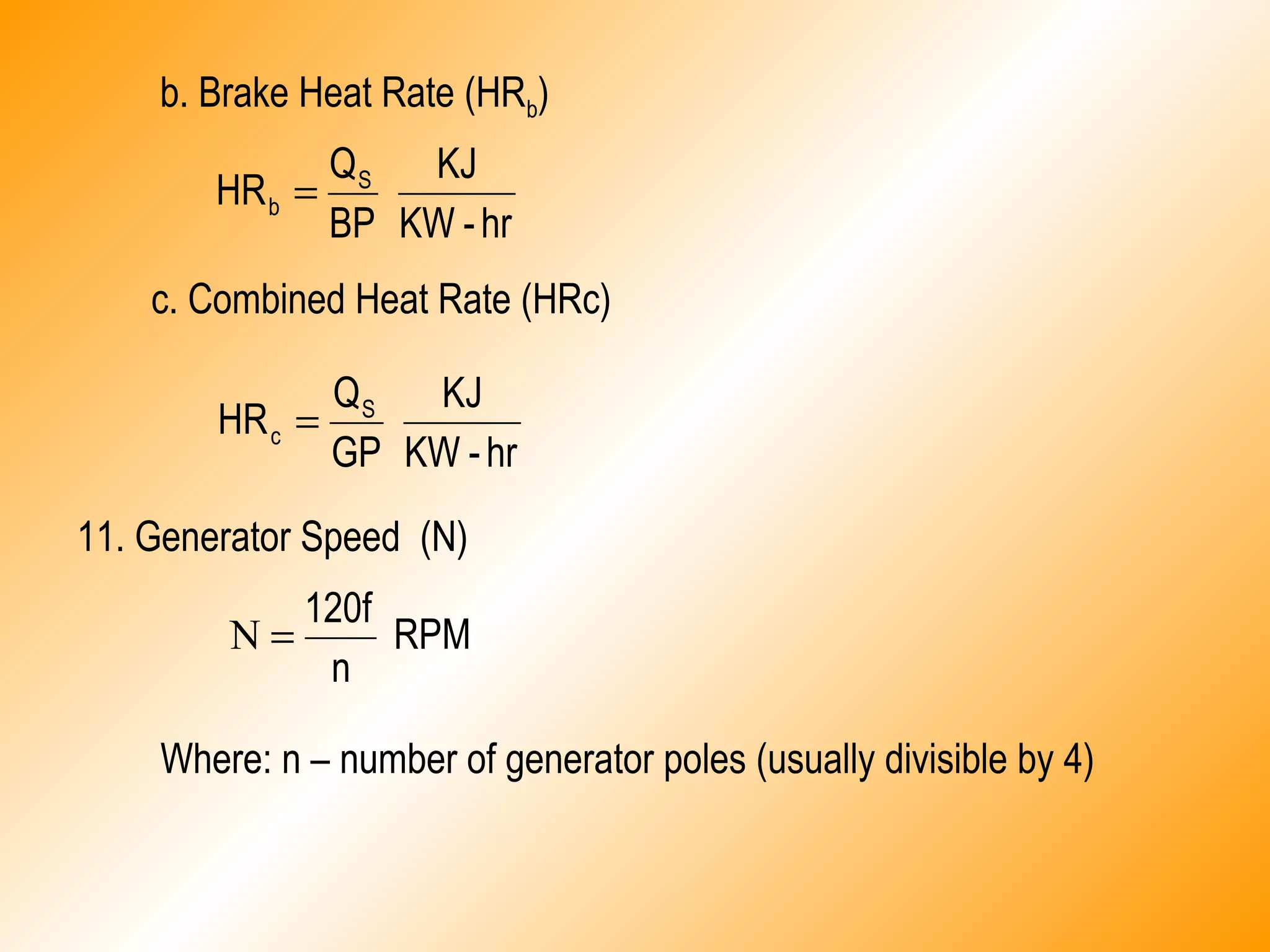
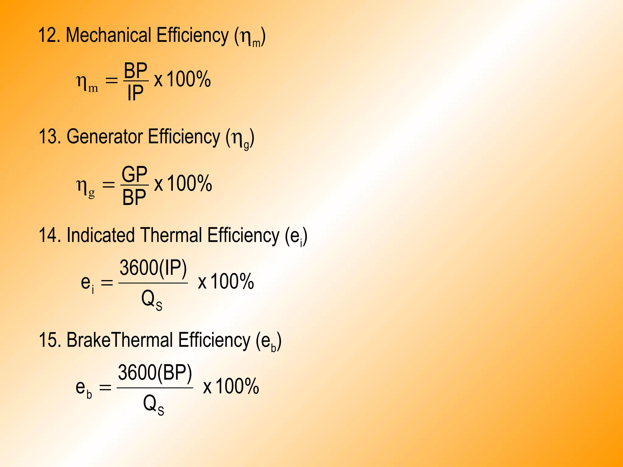
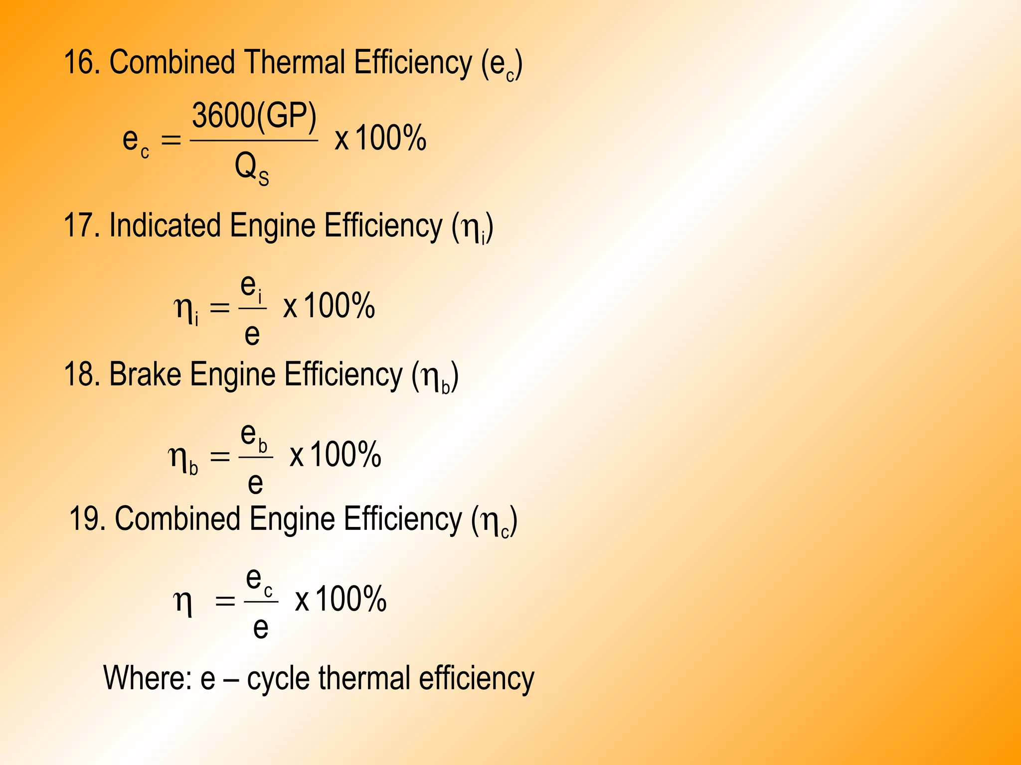
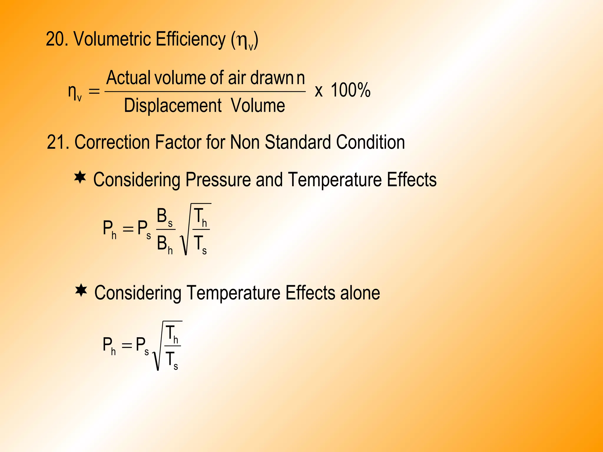
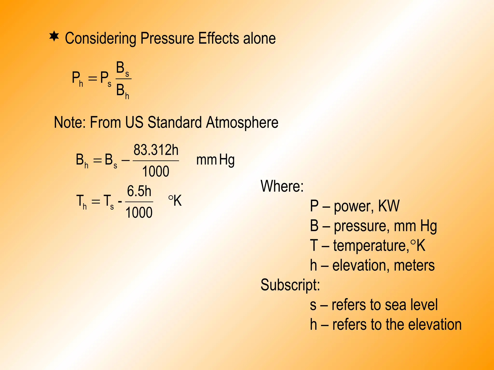
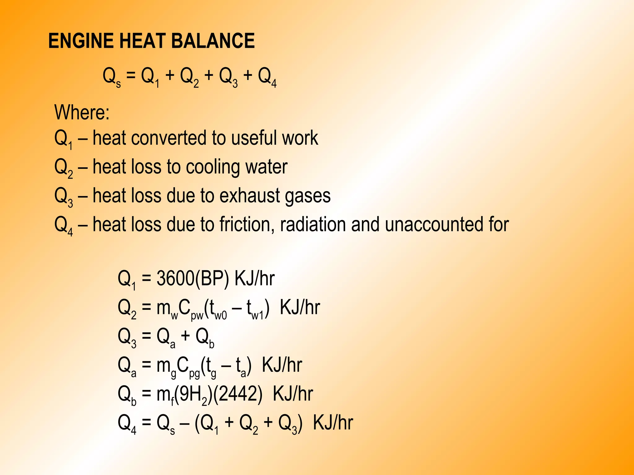
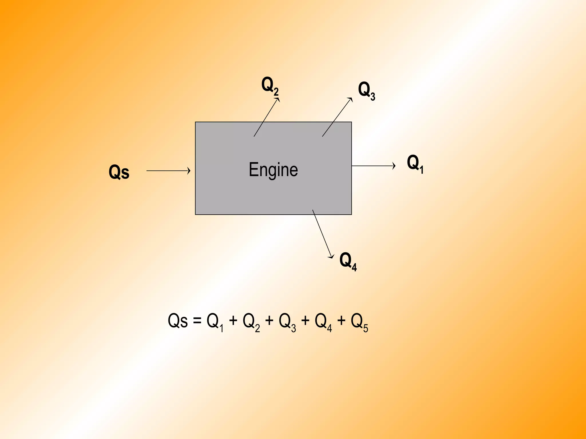

This document describes the components and operating principles of a diesel engine power plant. It discusses the four-stroke and two-stroke engine cycles, defines key performance metrics like indicated power, brake power, and efficiency, and provides equations to calculate these values based on factors like fuel heating value, engine speed, bore diameter, and pressure/temperature. It also presents the engine heat balance calculation that accounts for the heat from fuel converted to useful work versus heat lost to cooling, exhaust, and friction.


![[W f stoecker]_refrigeration_and_a_ir_conditioning_(book_zz.org)](https://cdn.slidesharecdn.com/ss_thumbnails/wfstoeckerrefrigerationandairconditioningbookzz-161019162540-thumbnail.jpg?width=640&height=640&fit=bounds)


![Vibe Coding vs. Spec-Driven Development [Free Meetup]](https://cdn.slidesharecdn.com/ss_thumbnails/vibecodingvsspecdrivendevelopment-251209105622-43f455e7-thumbnail.jpg?width=640&height=640&fit=bounds)


