Engine theory and calculations document discusses:
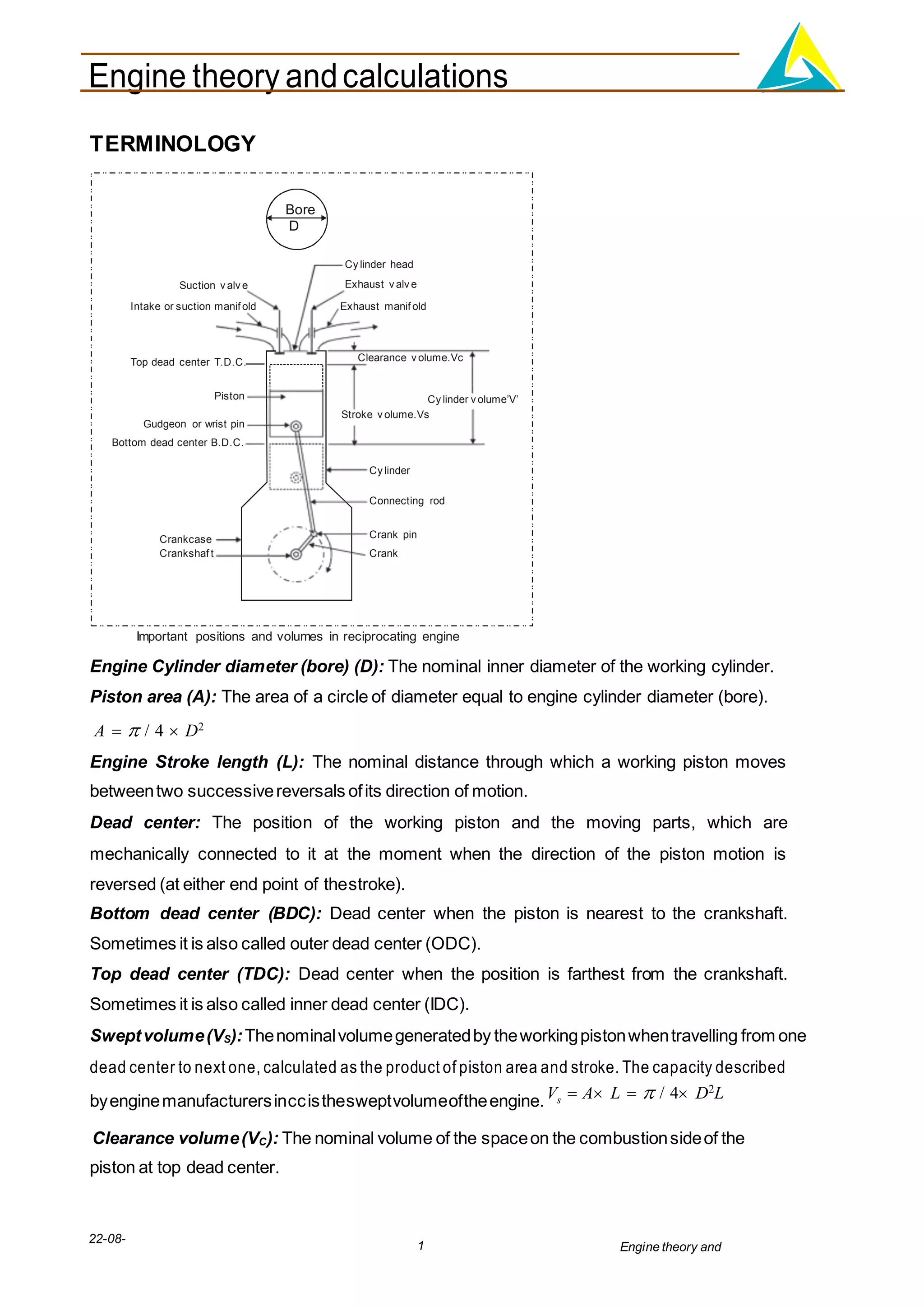
1. Important engine components and their functions like cylinder, piston, crankshaft etc.
2. Key engine parameters - bore, stroke, swept volume, clearance volume, compression ratio.
3. Working of 4-stroke and 2-stroke engine cycles in 3 steps each.
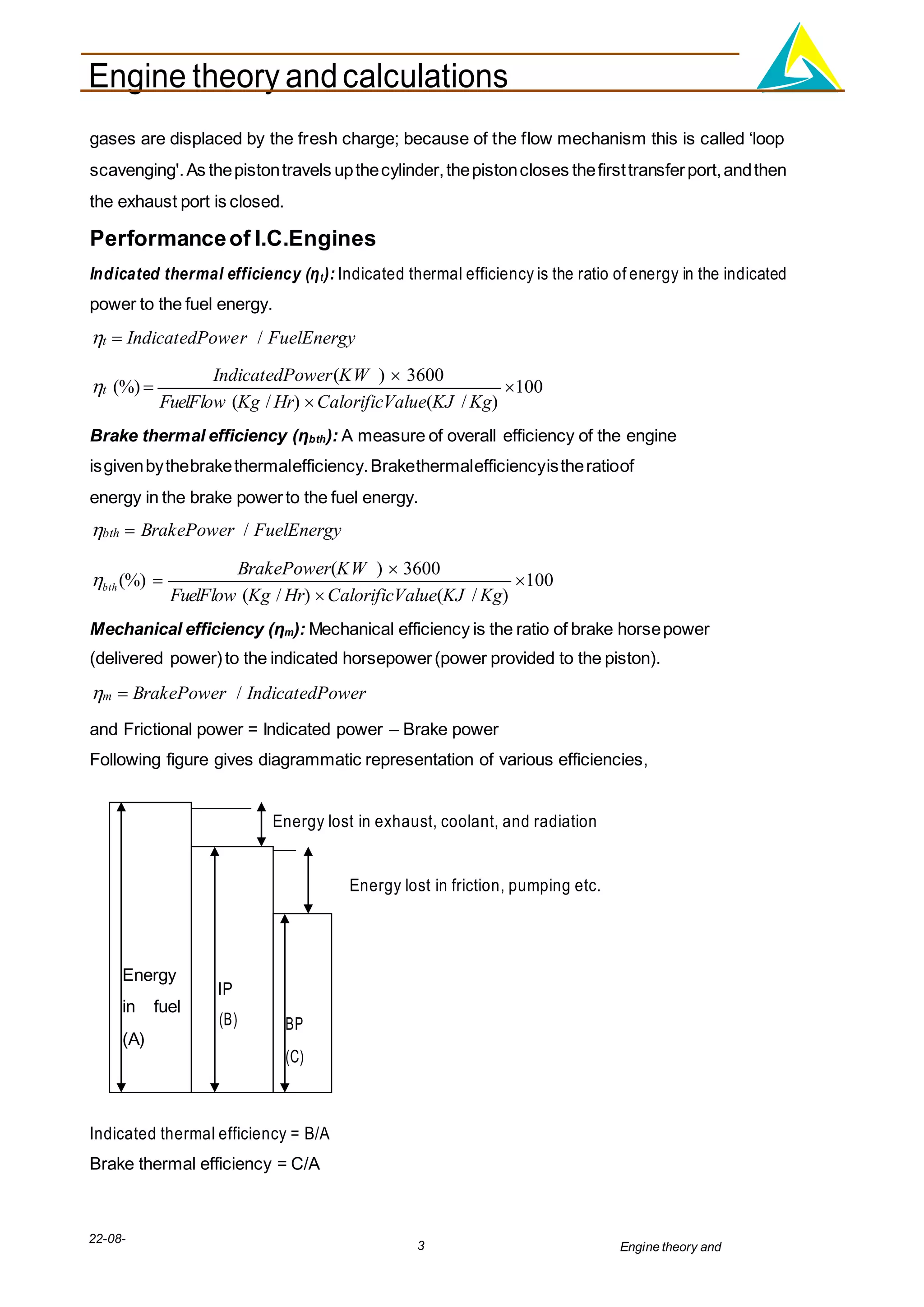
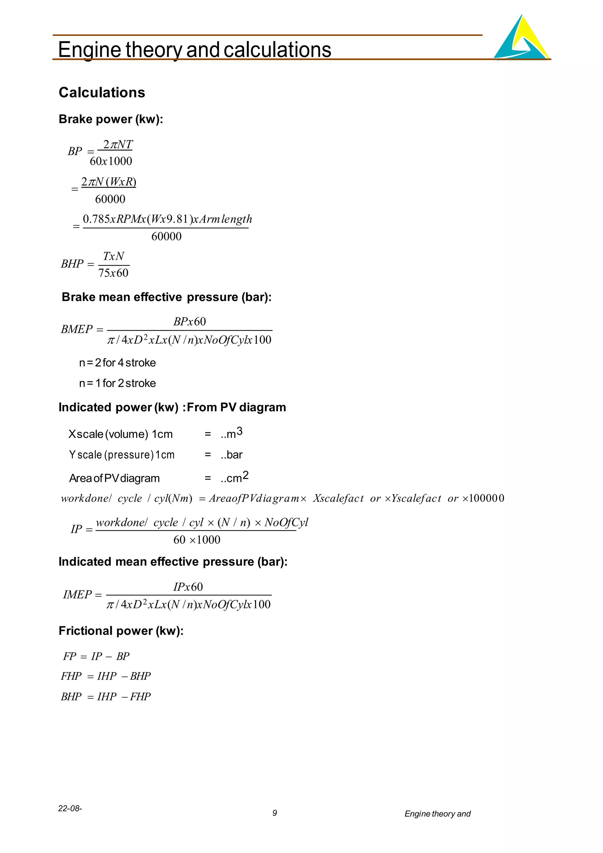
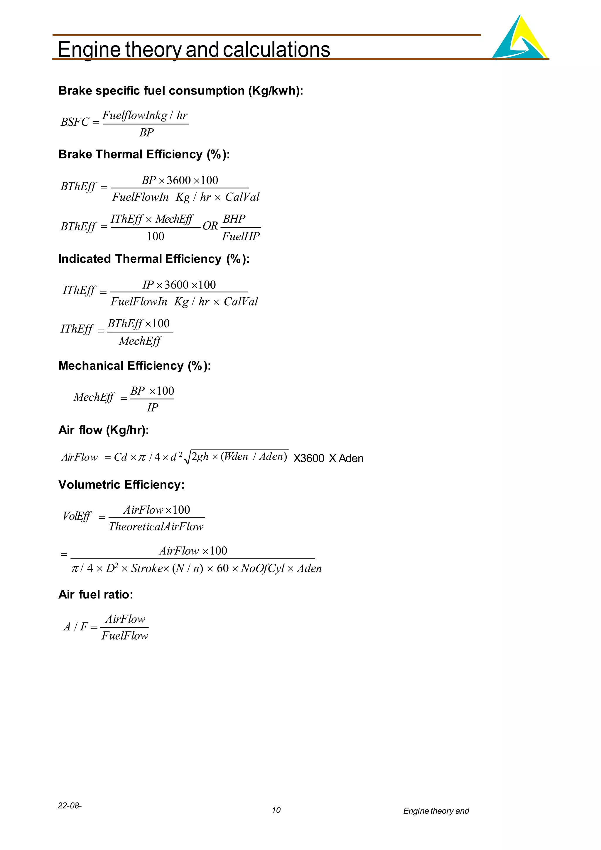
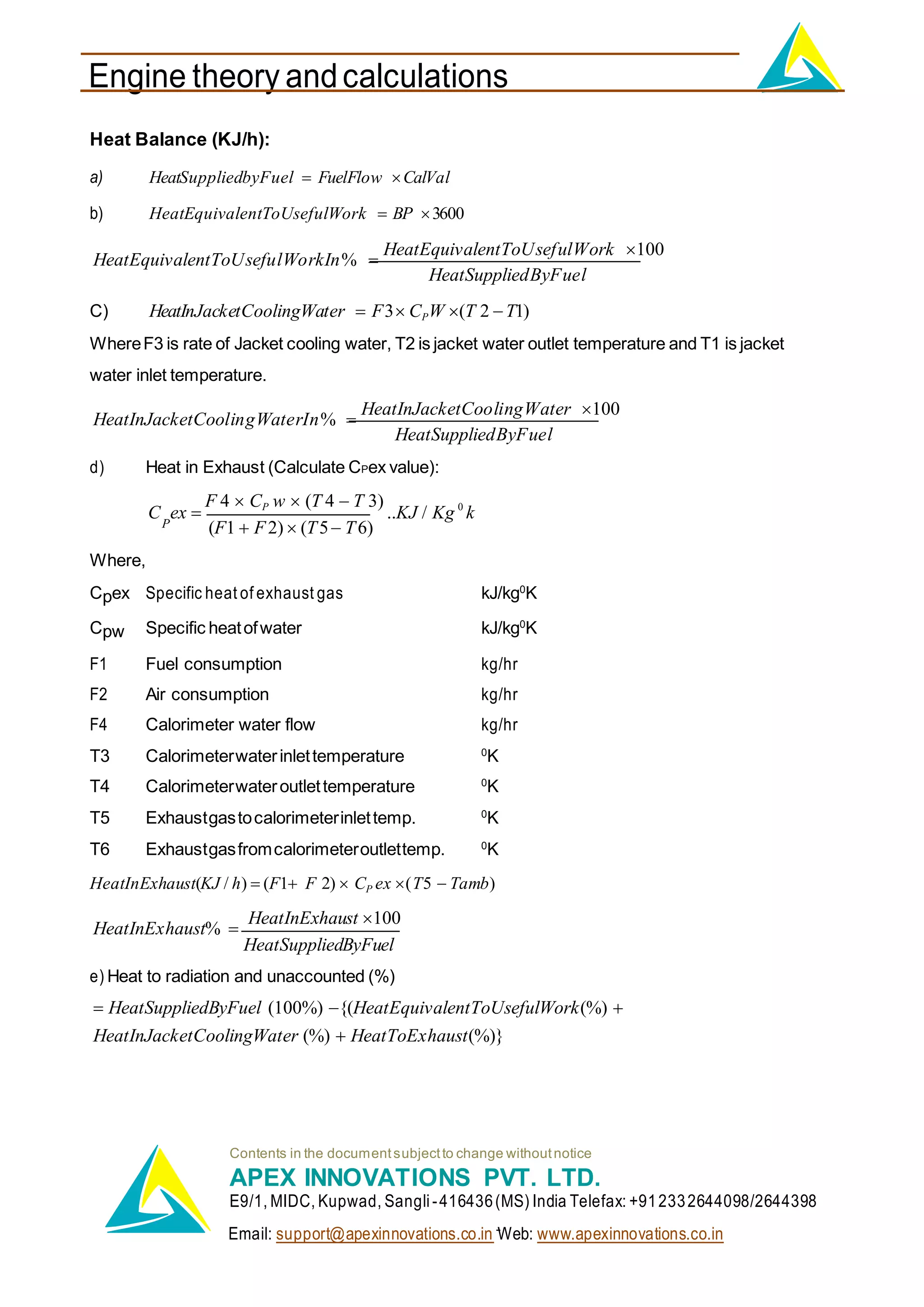
4. Performance parameters - indicated thermal efficiency, brake thermal efficiency, volumetric efficiency, specific fuel consumption.