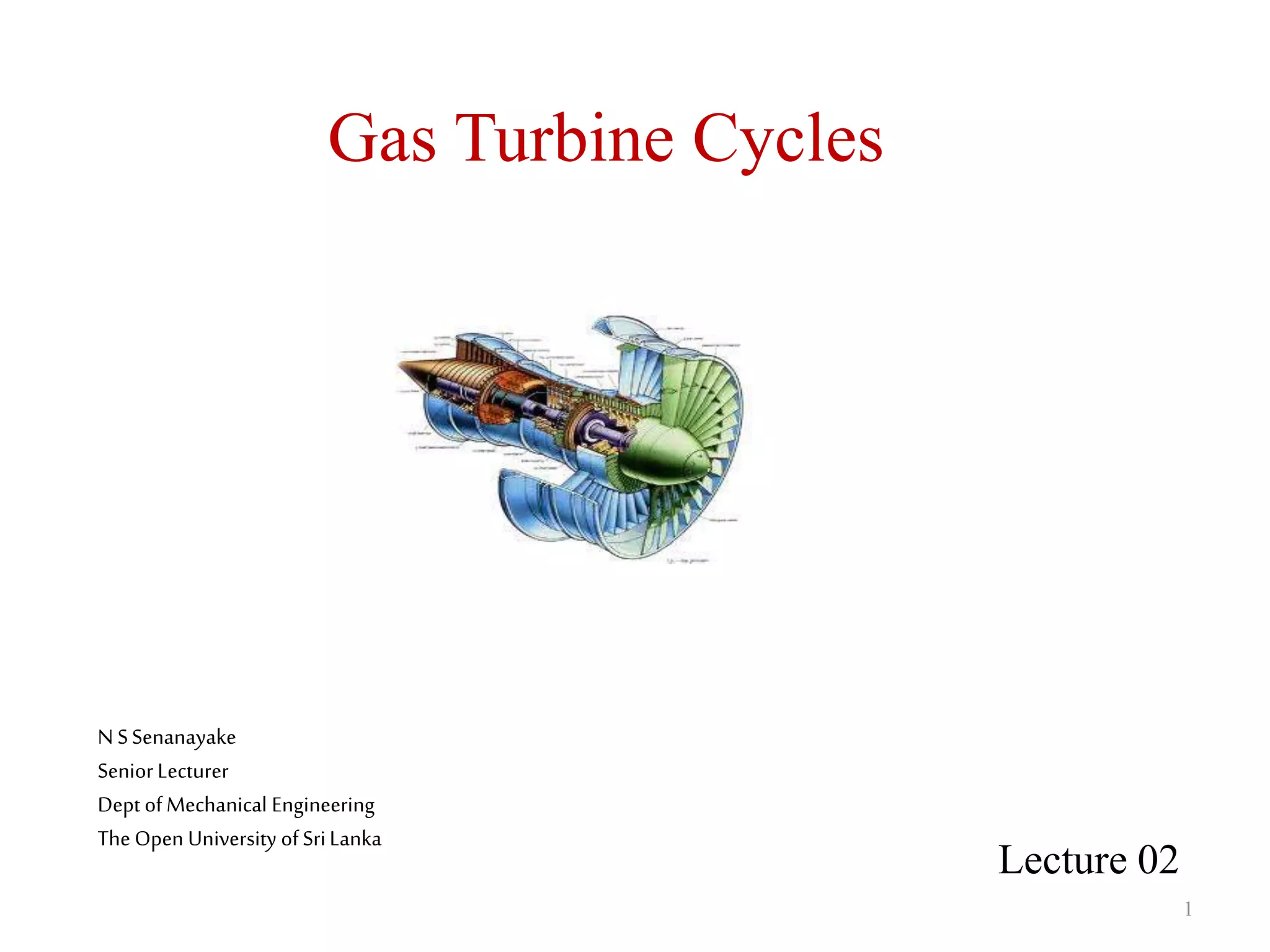
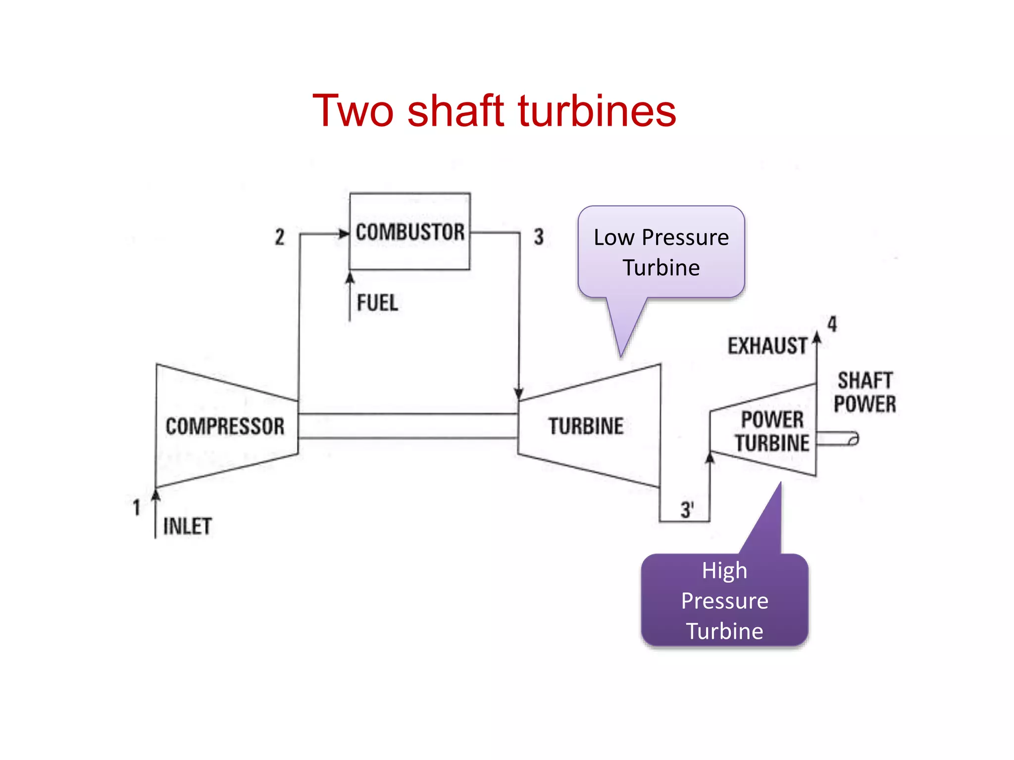
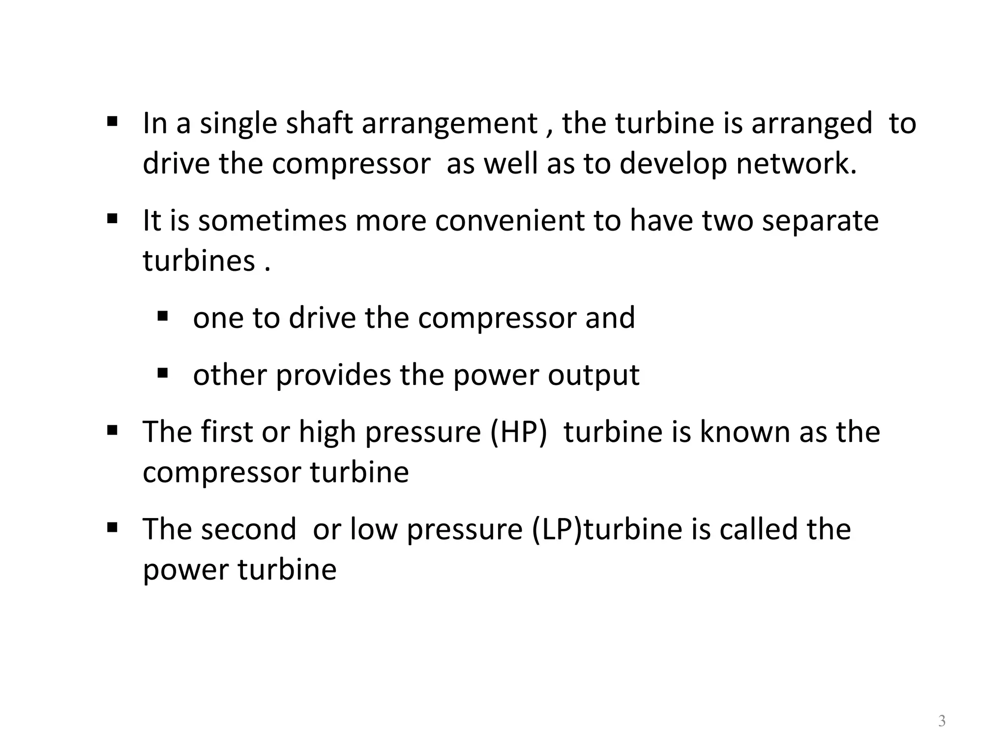
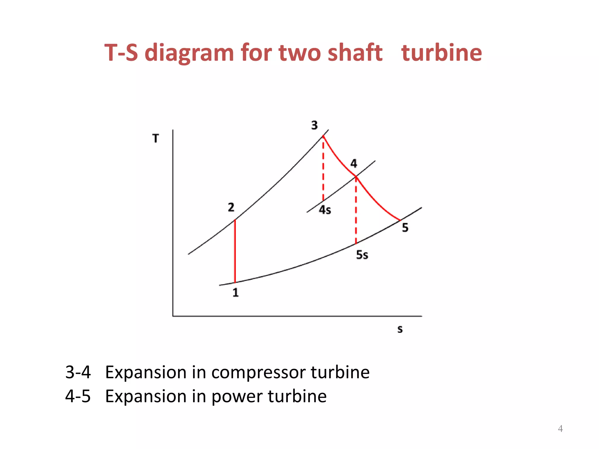
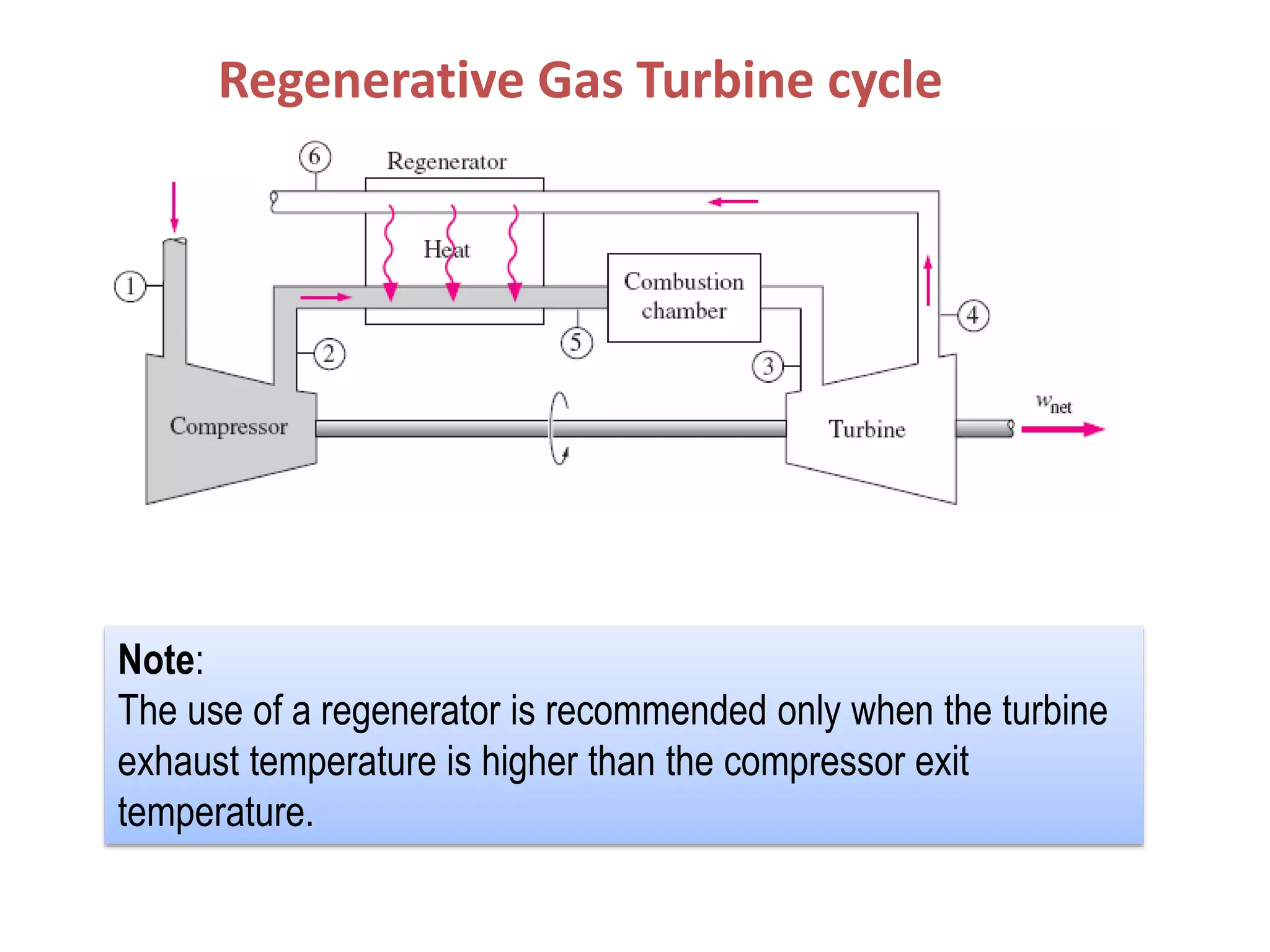
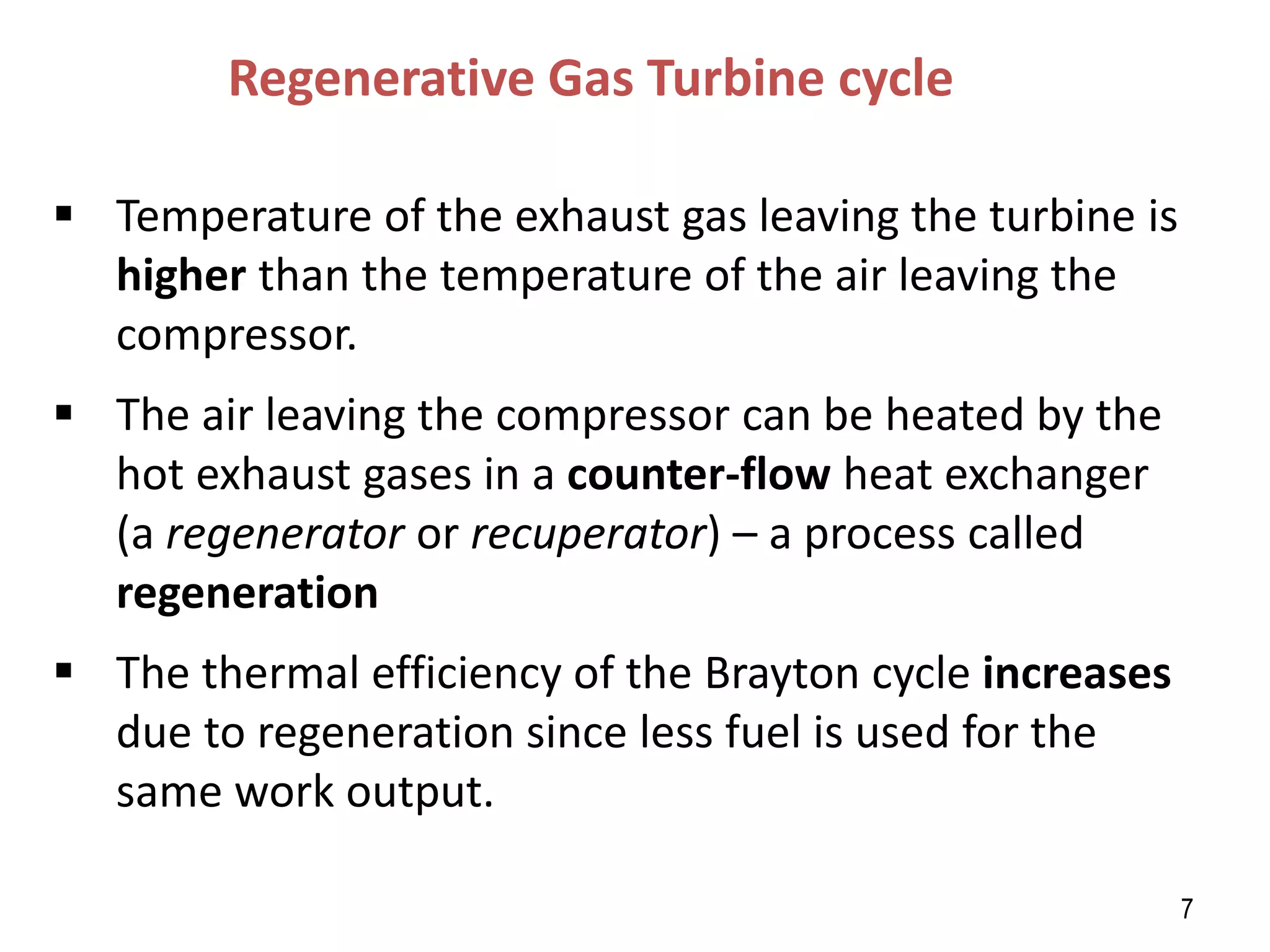
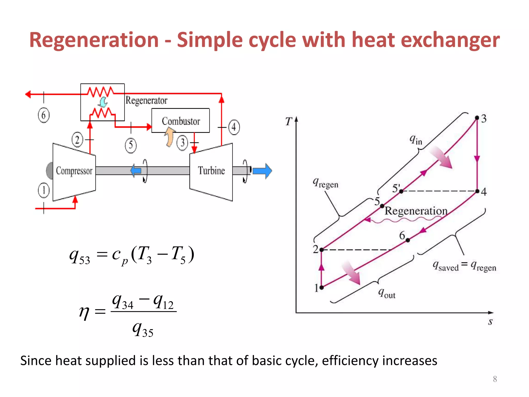
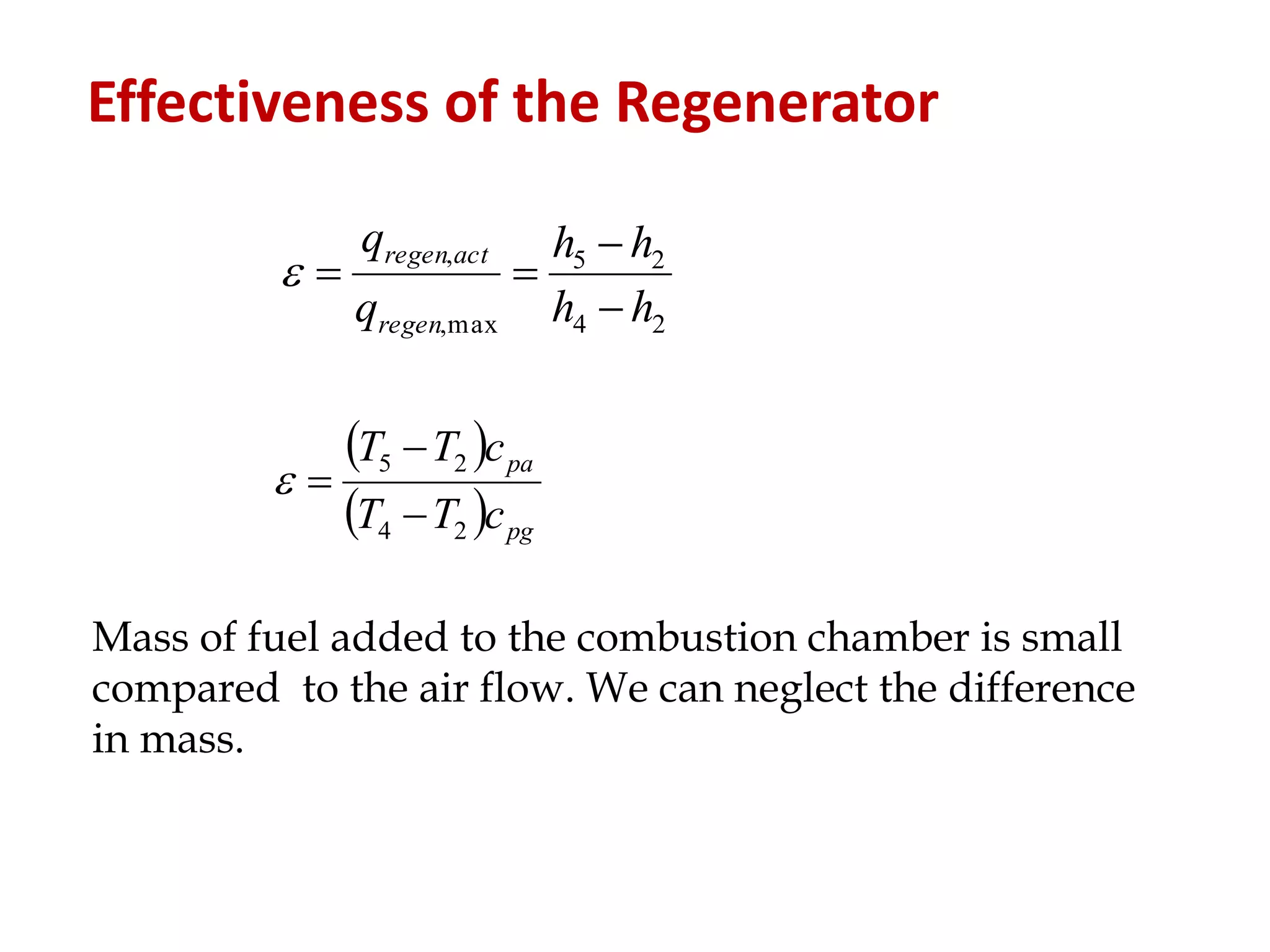
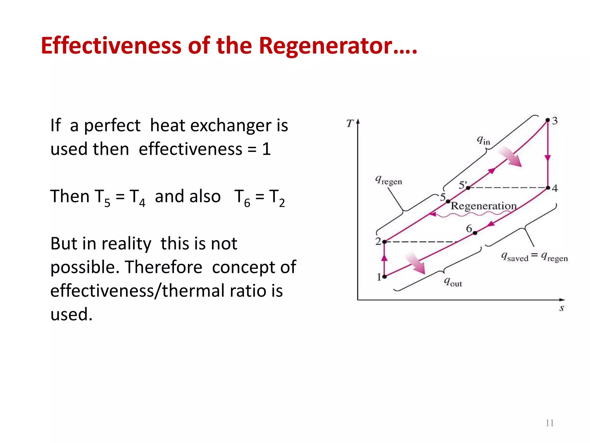
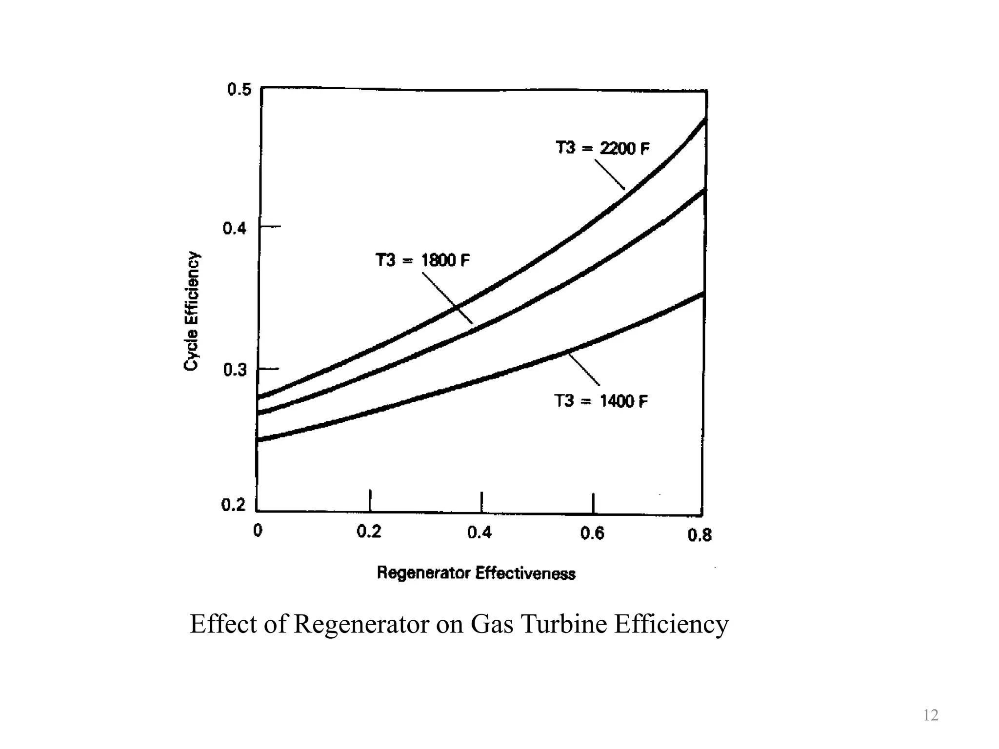
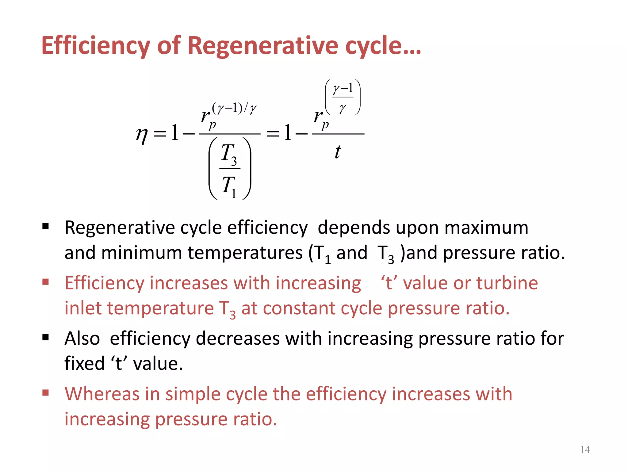
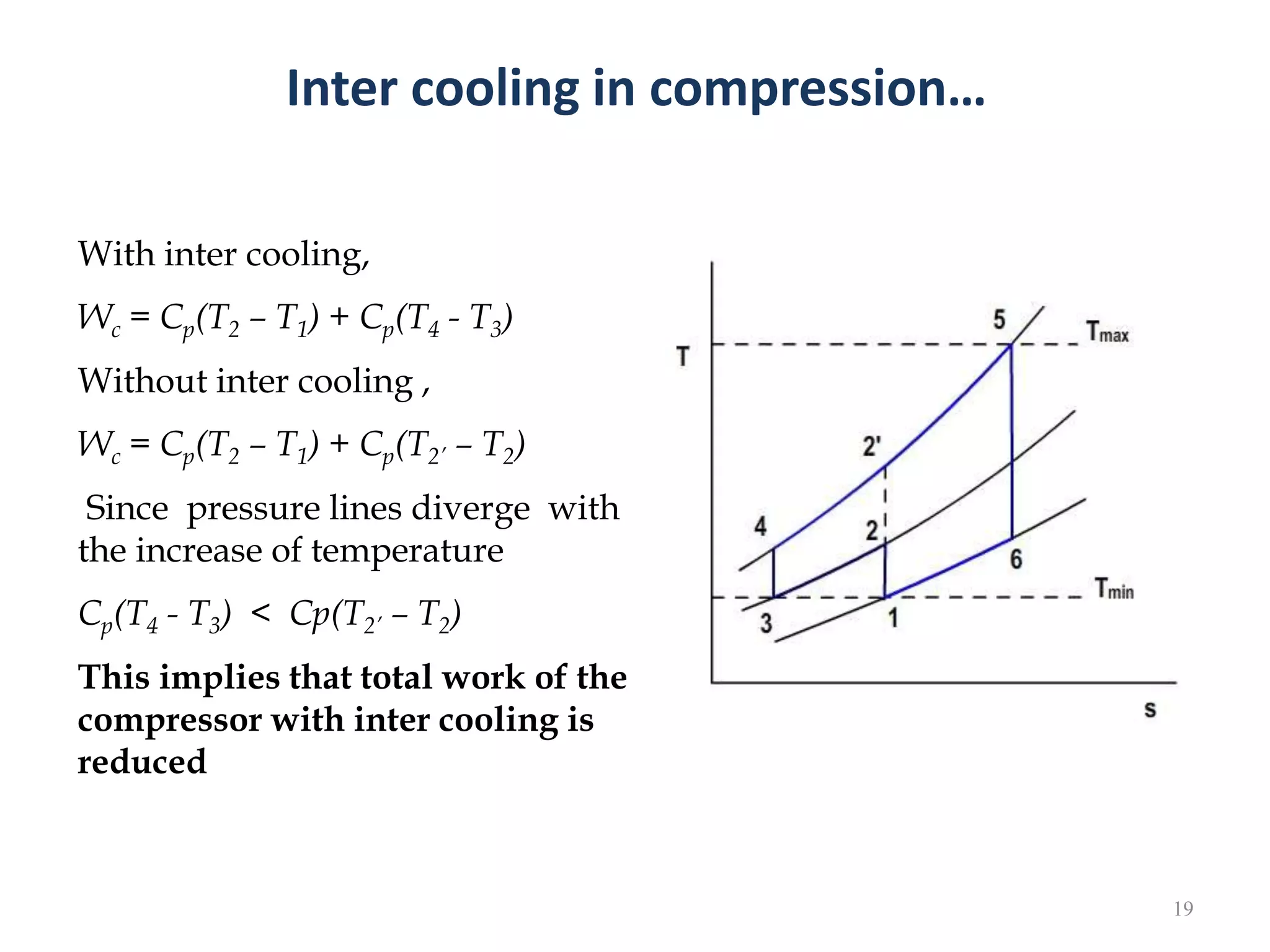
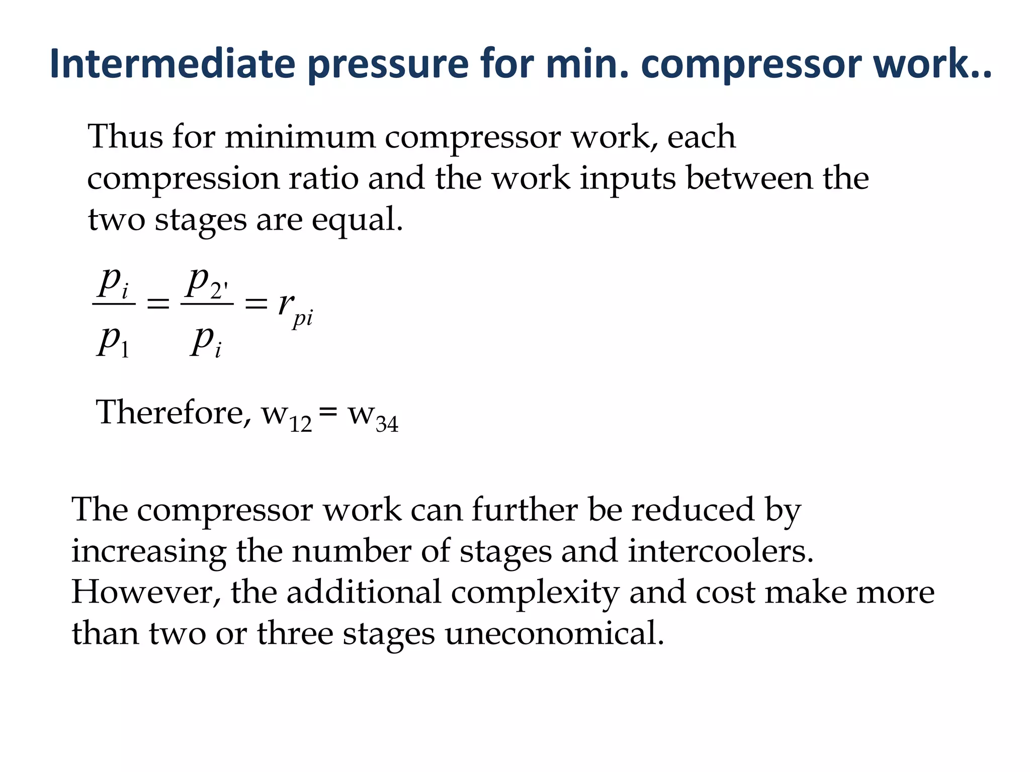
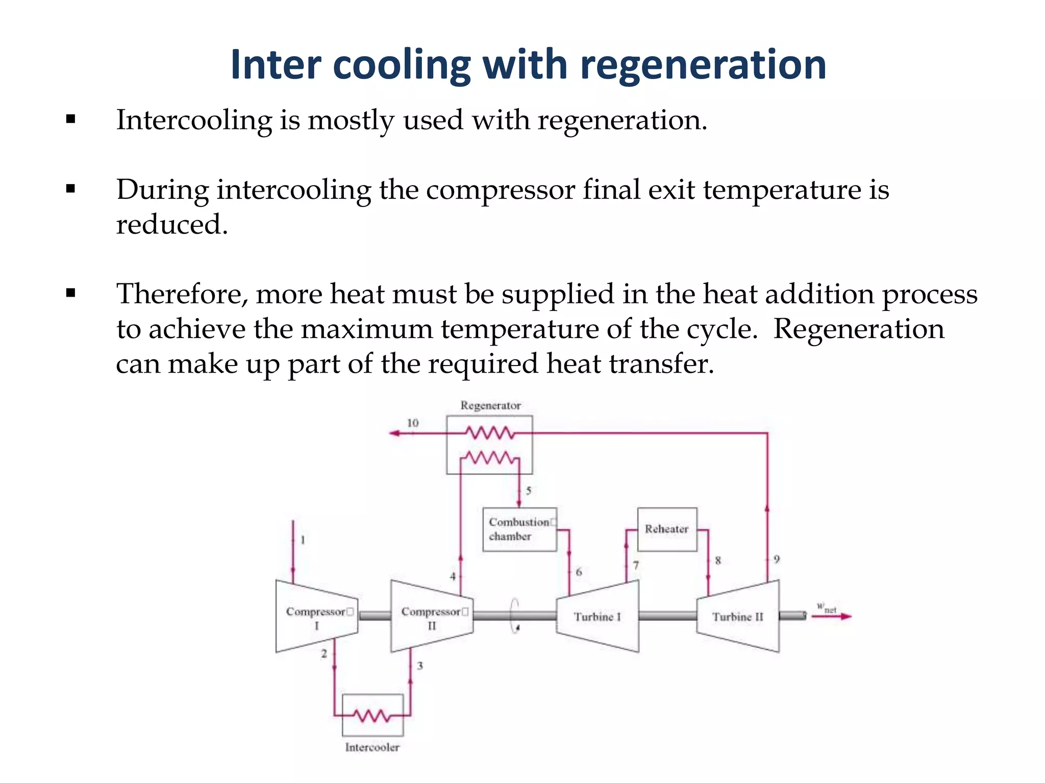
1. The document discusses gas turbine cycles with two shafts, where one turbine drives the compressor and the other provides power output. It describes regeneration using a heat exchanger to improve efficiency by heating the compressed air. Intercooling between compression stages and reheating are also discussed to reduce the work of compression. Examples are provided to calculate efficiency, power output, temperatures and pressures at different points in regenerative cycles with variations like intercooling.
3. 3
In a single shaft arrangement , the turbine is arranged to
drive the compressor as well as to develop network.
It is sometimes more convenient to have two separate
turbines .
one to drive the compressor and
other provides the power output
The first or high pressure (HP) turbine is known as the
compressor turbine
The second or low pressure (LP)turbine is called the
power turbine
4. 4
T-S diagram for two shaft turbine
3-4 Expansion in compressor turbine
4-5 Expansion in power turbine
6. 6
Note:
The use of a regenerator is recommended only when the turbine
exhaust temperature is higher than the compressor exit
temperature.
Regenerative Gas Turbine cycle
7. 7
Temperature of the exhaust gas leaving the turbine is
higher than the temperature of the air leaving the
compressor.
The air leaving the compressor can be heated by the
hot exhaust gases in a counter-flow heat exchanger
(a regenerator or recuperator) – a process called
regeneration
The thermal efficiency of the Brayton cycle increases
due to regeneration since less fuel is used for the
same work output.
Regenerative Gas Turbine cycle
8. Regeneration - Simple cycle with heat exchanger
8
)( 5353 TTcq p
35
1234
q
qq
Since heat supplied is less than that of basic cycle, efficiency increases
9. 9
Effectiveness of the Regenerator
Assuming the regenerator is
well insulated and changes in
kinetic and potential energies
are negligible, the actual and
maximum heat transfers from
the exhaust gases to the air can
be expressed as follows.
enthalpyavailableMax
enthalpyinIncrease
rregeneratoofessEffectiven
.
25, hhq actregen
10. 10
Effectiveness of the Regenerator
Mass of fuel added to the combustion chamber is small
compared to the air flow. We can neglect the difference
in mass.
pg
pa
cTT
cTT
24
25
24
25
max,
,
hh
hh
q
q
regen
actregen
11. 11
Effectiveness of the Regenerator….
If a perfect heat exchanger is
used then effectiveness = 1
Then T5 = T4 and also T6 = T2
But in reality this is not
possible. Therefore concept of
effectiveness/thermal ratio is
used.
13. Efficiency of Regenerative cycle
/)1(
3
1
1
pr
T
T
1
1
1
p
th
r
For simple cycle
Assume an ideal regenerator regen = 1 and constant specific heats
433 hhhhq xin
1243 hhhhwnet
43
12
43
12
11
TT
TT
hh
hh
Same equation for the
work ratio for basic cycle
14. 14
Regenerative cycle efficiency depends upon maximum
and minimum temperatures (T1 and T3 )and pressure ratio.
Efficiency increases with increasing ‘t’ value or turbine
inlet temperature T3 at constant cycle pressure ratio.
Also efficiency decreases with increasing pressure ratio for
fixed ‘t’ value.
Whereas in simple cycle the efficiency increases with
increasing pressure ratio.
t
r
T
T
r pp
1
1
3
/)1(
11
Efficiency of Regenerative cycle…
15. 15
Thermal efficiency of
Brayton cycle with
regeneration depends on:
Ratio of the minimum to
maximum temperatures
Pressure ratio
Regeneration is most
effective at lower pressure
ratios and small minimum-
to-maximum temperature
ratios.
Factors Affecting Thermal Efficiency
16. 16
The addition of a heat exchanger only improves the
cycle efficiency, but does not change the net work
output.
The net work can be increased either by reducing the
compressor work or by increasing the turbine work output
17. Heat exchanger
17
Gas turbine regenerators
are usually constructed as
shell-and-tube type heat
exchangers using very
small diameter tubes, with
the high pressure air inside
the tubes and low
pressure exhaust gas in
multiple passes outside
the tubes
18. Intercooling in compression
18
The state 1 is the
atmospheric condition
Ideally, it is possible to cool
the air to the atmospheric
temperature and in this case
inter cooling is said to be
complete inter cooling.
19. Inter cooling in compression…
19
With inter cooling,
Wc = Cp(T2 – T1) + Cp(T4 - T3)
Without inter cooling ,
Wc = Cp(T2 – T1) + Cp(T2’ – T2)
Since pressure lines diverge with
the increase of temperature
Cp(T4 - T3) < Cp(T2’ – T2)
This implies that total work of the
compressor with inter cooling is
reduced
20. 20
Therefore if the compression is carried out to high pressure (state 2 )
in two stages, 1 -2 and 3- 4 with the air cooled at constant pressure pi
between the stages, a reduction of compressor work can be obtained.
Net work is increased. Hence Work ratio is increased.
Also when compression is done at lower temperatures, the work
input to the compressor is reduced. Thus increases net work and
hence increase the thermal efficiency
The back work ratio of a gas- turbine improves as a result of inter
cooling and reheating. However, inter cooling and reheating
decreases thermal efficiency unless they are accompanied with
regeneration.
Inter cooling in compression…
21. 21
With isentropic compression and complete inter cooling the
compression work is given by the following expression
)()( 3412 TTcTTcw ppcomp
/)1(
'2
3
4
/)1(
11
2
i
i
p
p
T
T
and
p
p
T
T
Also we know that,
Intermediate pressure for min. compressor work
1
'
1
/)1(
2
1
/)1(
1
1
i
p
i
pcomp
p
p
Tc
p
p
Tcw
22. 22
The saving of work depends on the choice of the intermediate
pressure pi.
By equating dW/dpi to zero the condition for minimum work can be
proved to be;
)( '21 pppi
ppi r
p
p
r
1
'2
pi
i
i
r
p
p
p
p
'2
1
Therefore we can write
rpi = compression ratio at each stage
Intermediate pressure for min. compressor work..
23. Thus for minimum compressor work, each
compression ratio and the work inputs between the
two stages are equal.
The compressor work can further be reduced by
increasing the number of stages and intercoolers.
However, the additional complexity and cost make more
than two or three stages uneconomical.
pi
i
i
r
p
p
p
p
'2
1
Therefore, w12 = w34
Intermediate pressure for min. compressor work..
24. 24
Intercooling is mostly used with regeneration.
During intercooling the compressor final exit temperature is
reduced.
Therefore, more heat must be supplied in the heat addition process
to achieve the maximum temperature of the cycle. Regeneration
can make up part of the required heat transfer.
Inter cooling with regeneration
26. Example 1 – Two shaft plant
26
Air is drawn in a gas turbine unit at 15°C and 1.01 bar and pressure ratio is
7 :1. The compressor is driven by the HP turbine and LP turbine drives a
separate power shaft. The isentropic efficiencies of compressor, and the HP
and LP turbines are 0.82, 0.85 and 0.85 respectively. If the maximum cycle
temperature is 610oC, Calculate:
(i) The pressure and temperature of the gases are entering the power
turbine.
(ii) The net power developed by the unit per kg/s, mass flow.
(iii) The work ratio
(iv) The thermal efficiency of the unit.
Neglect the mass of fuel and assume the following
For compression process Cpa = 1.005 kJ/kgK γ = 1.4
For combustion and expansion process Cpg = 1.15kJ/kgK and γ = 1.333
27. 27
In a gas turbine plant, air is compressed from 1.01 bar and 15°C
through a pressure ratio of 4:1. It is then heated to 650°C in a
combustion chamber and expanded back to original pressure of
1.01 bar.
Calculate the cycle efficiency and the specific power output if a
perfect heat exchanger is employed. The isentropic efficiencies
of the turbine and compressor are 0.85 and 0.8 respectively.
Example 2 – Regeneration with perfect HE
28. 28
In a gas turbine installation air is supplied at 1bar, 25°C into compressor.
The pressure after compression is 7.2 bar. The gas leaves the
combustion chamber at 1100°C. A heat exchanger having effectiveness
of 0.8 is fitted at exit of turbine for heating the air before its inlet into
combustion chamber. Isentropic efficiency of the compressor and
turbine are 0.8 and 0.85 respectively. The heat transfer rate to the
combustion chamber is 1.48MW
The adiabatic index is 1.4 for air and 1.33 for the gas produced by
combustion. The specific heat Cp is 1.005 kJ/kgK for air and 1.15kJ/kgK
for the gas. Determine the following.
mass flow rate
net power output
thermal efficiency of the cycle
Example 3 – Regeneration with non perfect HE
29. 29
In a gas turbine plant working on the Brayton cycle the air at
inlet is at 27ºC, 0.1 MPa. Compression is divided into two
stage , each of pressure ratio 2.5 and efficiency 80% with inter
cooling to 27ºC.The maximum temperature of the cycle is
800ºC. Turbine isentropic efficiency is 80%.
Find
The cycle efficiency
The turbine exhaust temperature
Example 4 – Inter cooling
30. 30
The air supplied to a gas turbine plant is 10 kg/s. The pressure
ratio is 6 and pressure at the inlet of the compressor is 1 bar. The
compressor is two stage and provided with perfect intercooler.
The inlet temperature is 300K and maximum temperature of the
cycle is limited to 1073K.
Isentropic efficiency of compressor stage is 80% and turbine
stage is 85%. A regenerator having effectiveness of 0.7. is
included. Neglecting the mass of fuel determine the power
output and the thermal efficiency of the plant.
Example 5 – Inter cooling and regeneration
31. 31
The air in a gas turbine plant is taken in LP compressor at
293K and 1.05 bar and after compression it is passed through
intercooler where its temperature is reduced to 300K. The
cooled air is further compressed in HP unit and then passed
in the combustion chamber where its temperature is
increased to 750°C by burning the fuel. The combustion
products expand in HP turbine which runs the compressor
and further expansion is continued in LP turbine which runs
the alternator. The gases coming out from LP turbine are
used for heating the incoming air from HP compressor and
then expanded to atmosphere pressure.
Example 6 – Inter cooling and regeneration with two shafts
32. 32
Pressure ratio of each compressor - 2.
Isentropic efficiency of each turbine and compressor - 82%
Effectiveness of Heat exchanger- 0.72
Air flow – 16 kg/s
Calorific value of fuel – 42000 kJ/kg
Cp for air – 1.005 kJ/kg K
Cp for gas - 1.12 kJ/kg K
γ for air - 1.4
γ for gas – 1.33
Neglecting the mechanical, pressure and heat losses of the
system, determine the following
The power output
Specific fuel consumption
Thermal efficiency
33. 33
(i) Why are the back work ratios relatively high in gas turbine
plants compared to that of steam power plant?
(ii) In a gas turbine plant compression is carried out in two
stages with perfect intercooling and expansion in one
stage turbine. If the maximum temperature (Tmax) and
minimum temperature (Tmin ) in the cycle remain constant,
show that for maximum specific output of the plant, the
optimum overall pressure ratio is given by
Inter cooling - Optimum pressure ratio for maximum
specific work output
Example 7
34. 34
Where γ = adiabatic index
ηT = Isentropic efficiency of the turbine
ηC = Isentropic efficiency of the turbine
35. 35
(iii) In a Brayton cycle gas turbine power plant the minimum
and maximum temperature of the cycle are 300K and
1200K. The compression is carried out in two stages of
equal pressure ratio with inter cooling of the working fluid
to the minimum temperature of the cycle after the first
stage of compression. The entire expansion is carried out in
one stage only. The isentropic efficiency of both
compressors is 0.8 and that of the turbine is 0.9.
Determine the overall pressure ratio that would give the
maximum work per kg working fluid . Take γ = 1.4.